
Computer Vision for Robotics (Vision Foundations) · Lesson 14
Depth & 3D Vision
Est. 50–65 min
Why
Why this lesson matters
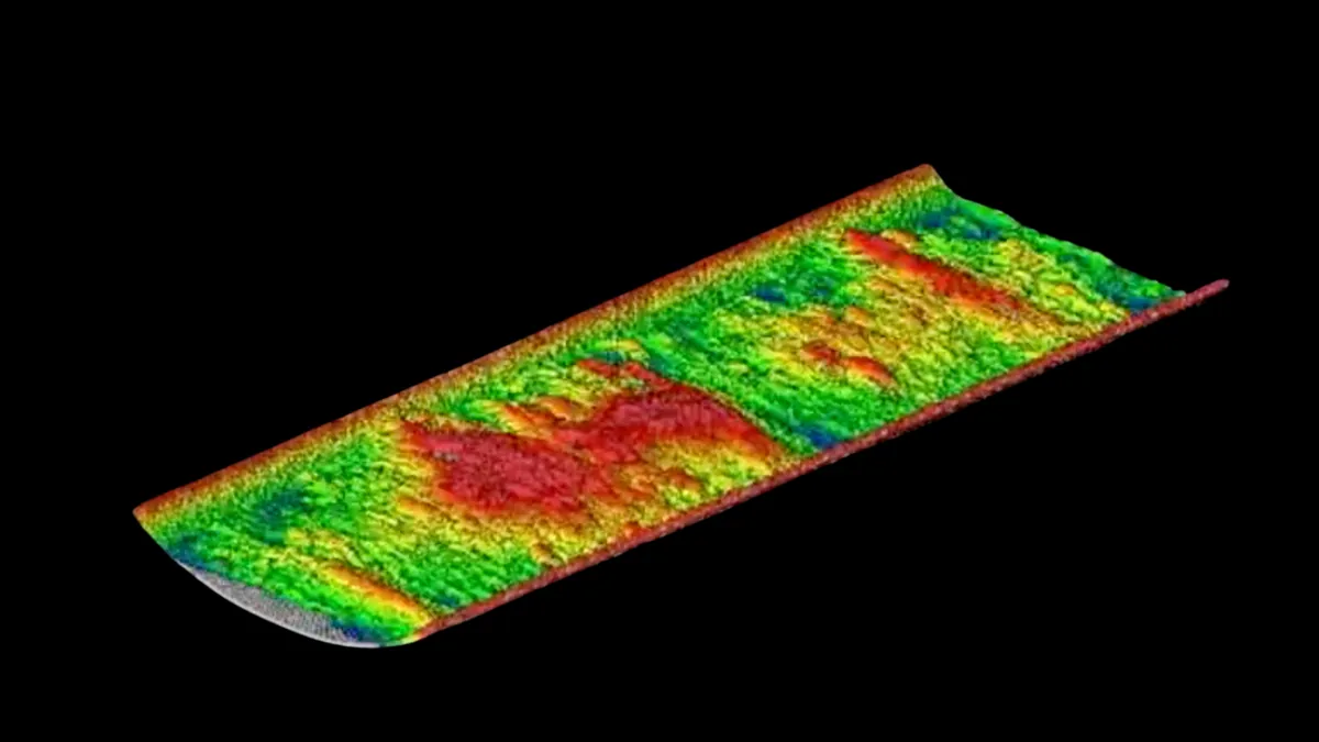
In Lesson 13 you saw that one image loses depth: a pixel is a whole ray. Depth vision gets the missing Z back — with two cameras (stereo), with a sensor that sends out its own light (active depth), or with a laser scanner (lidar). Once every pixel has a Z, you can build a point cloud: a 3D picture of the table that tells the arm how tall things are and what is in front of what.
Concept
Getting Z back: stereo, disparity and point clouds
1. Two eyes, one rule
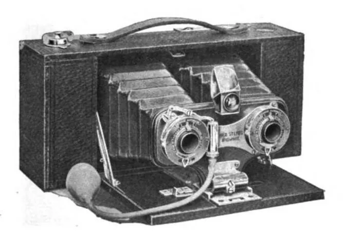
Put two identical cameras side by side, a distance B (the baseline) apart, both looking forward. A point appears at column x in the left image and at x′ in the right image. The difference d = x − x′ is the disparity. Similar triangles give the stereo rule: Z = f · B / d. Near things shift a lot between the two images; far things shift very little.
| Distance Z | Disparity (f = 700 px, B = 60 mm) | Depth error from a 0.25 px matching error |
|---|---|---|
| 300 mm | 140 px | ± 0.5 mm |
| 600 mm | 70 px | ± 2.1 mm |
| 1200 mm | 35 px | ± 8.6 mm |
| 2400 mm | 17.5 px | ± 34.3 mm |
2. The stereo pipeline
Calibrate both cameras
Each camera needs its own K and distortion (Lesson 12), plus the rotation and translation between them.
Undistort and rectify
Warp both images so they look like two perfect pinhole cameras on the same plane. Then a point in row v of the left image is in the *same row* of the right image, and matching only has to search left–right.
Match and compute disparity
A matcher such as OpenCV’s
StereoBMorStereoSGBMcompares small blocks along each row and keeps the best match. The result is a disparity map.Disparity → depth → 3D
Z = f·B/d for each pixel, then X = (u − cx)·Z/f and Y = (v − cy)·Z/f. All the points together are a point cloud.
Visual
Visualise it: the depth explorer
Explore how baseline, focal length and distance change disparity and depth error. Educational model — not a real sensor driver.
Interactive · Depth vision explorer · Educational

Z ≈ (f·b)/d recovers camera-frame depth; align RGB+(u,v)+Z → XYZ, then TF to base for Stage 8 IK. Synthetic depth only — not a depth camera / not OpenCV stereo.
Code lab
Code lab: a stereo pair, a depth map and a point cloud
We build a perfectly rectified synthetic stereo pair so that we know the true depth everywhere: a textured table 700 mm away, block A (60 mm tall, top at 640 mm), block B (100 mm tall, top at 600 mm), and one plain grey sheet with no texture. Both images get camera noise. Then cv.StereoSGBM computes disparity, and we turn it into depth, a 3D point and a point cloud.
"""Stage 11 L14 - Depth from two cameras (stereo), with numbers you can check.

1) Depth from disparity: Z = f * B / d, and why far depth is noisy
2) Make a synthetic stereo pair of a table with two blocks, run cv.StereoSGBM
3) Read a block's depth, then turn its pixels into a 3D point (X, Y, Z)
4) Back-project the depth image into a point cloud and find the block height

Needs: opencv-python, numpy.   Run: python stereo_depth_lab.py
"""
import cv2 as cv
import numpy as np

f, B = 700.0, 60.0                    # focal length (px) and baseline (mm) of our stereo rig
W, H = 640, 480
cx, cy = W / 2, H / 2

# --- 1) the stereo rule --------------------------------------------------------------
print('1) Z = f * B / d   (f = 700 px, B = 60 mm)')
for Z in (300, 600, 1200, 2400):
    d = f * B / Z
    dz = Z * Z / (f * B) * 0.25                  # depth change caused by a 0.25 px disparity error
    print(f'   Z = {Z:4d} mm -> disparity {d:6.1f} px ; 0.25 px error = +/- {dz:5.1f} mm')

# --- 2) synthetic stereo pair -----------------------------------------------------------
rng = np.random.default_rng(14)
texture = cv.GaussianBlur((rng.random((H, W + 200)) * 255).astype(np.uint8), (3, 3), 0)
Z = np.full((H, W), 700.0)                       # table plane 700 mm away (camera looks at it)
Z[180:300, 150:270] = 640.0                      # block A: 60 mm tall
Z[220:320, 380:500] = 600.0                      # block B: 100 mm tall
disp_true = f * B / Z

left = texture[:, 100:100 + W].copy()
# Each left pixel x appears at x - d in the right image. Paint far points first,
# so nearer points (bigger d) cover them - just like a real occlusion.
right = np.zeros_like(left)
order = np.argsort(disp_true, axis=None)                    # far (small d) -> near (big d)
ys, xs = np.unravel_index(order, disp_true.shape)
xr = np.round(xs - disp_true[ys, xs]).astype(int)
ok = xr >= 0
right[ys[ok], xr[ok]] = left[ys[ok], xs[ok]]
holes = right == 0                                          # areas hidden behind the blocks
right[holes] = texture[:, :W][holes]                        # fill with background texture
left[400:470, 40:200] = 128                                 # a plain grey sheet: no texture
right[400:470, 0:200] = 128
noise = lambda im: np.clip(im + rng.normal(0, 4, im.shape), 0, 255).astype(np.uint8)
left, right = noise(left), noise(right)                     # camera noise in both images

sgbm = cv.StereoSGBM_create(minDisparity=32, numDisparities=48, blockSize=7,
                            P1=8 * 7 * 7, P2=32 * 7 * 7, uniquenessRatio=5)
disp = sgbm.compute(left, right).astype(np.float32) / 16.0      # SGBM returns disparity x16
valid = disp > 32
Zest = np.where(valid, f * B / np.maximum(disp, 1e-6), np.nan)
cv.imwrite('left.png', left)
cv.imwrite('disparity.png', cv.normalize(np.nan_to_num(disp), None, 0, 255, cv.NORM_MINMAX).astype(np.uint8))

print('\n2) StereoSGBM on the synthetic pair')
print(f'   valid pixels: {valid.mean() * 100:.0f}%  (the left edge has no match in the right image)')
for name, (y0, y1, x0, x1), zt in [('table', (380, 460, 300, 600), 700), ('block A', (200, 280, 170, 250), 640),
                                   ('block B', (240, 300, 400, 480), 600),
                                   ('grey sheet', (410, 460, 130, 190), 700)]:
    roi = Zest[y0:y1, x0:x1]
    good = np.isfinite(roi).mean() * 100
    if good < 5:
        print(f'   {name:10s} true {zt} mm -> no depth ({good:.0f}% valid pixels)')
        continue
    print(f'   {name:10s} true {zt} mm -> median {np.nanmedian(roi):6.1f} mm, {good:3.0f}% valid, '
          f'spread {np.nanpercentile(roi, 90) - np.nanpercentile(roi, 10):5.1f} mm')

# --- 3) one pixel + depth = one 3D point ------------------------------------------------
u, v = 440, 270                                   # centre of block B
z = np.nanmedian(Zest[v - 10:v + 10, u - 10:u + 10])      # median of a small window: robust
X, Y = (u - cx) * z / f, (v - cy) * z / f
print(f'\n3) Block B centre pixel ({u}, {v}) with depth {z:.1f} mm -> 3D point X {X:.1f}, Y {Y:.1f}, Z {z:.1f} mm')
print(f'   true point: X {(u - cx) * 600 / f:.1f}, Y {(v - cy) * 600 / f:.1f}, Z 600.0 mm')

# --- 4) point cloud ---------------------------------------------------------------------
vv, uu = np.mgrid[0:H, 0:W]
pts = np.dstack([(uu - cx) * Zest / f, (vv - cy) * Zest / f, Zest]).reshape(-1, 3)
pts = pts[~np.isnan(pts[:, 2])]
table_z = np.median(pts[:, 2])
height = table_z - pts[:, 2]
print(f'\n4) Point cloud: {len(pts):,} points; table at {table_z:.0f} mm')
print(f'   points more than 30 mm above the table: {(height > 30).sum():,}')
print(f'   tallest object height ~ {np.percentile(height, 99.5):.0f} mm (true 100 mm)')
np.save('cloud.npy', pts.astype(np.float32))
print('saved left.png, disparity.png, cloud.npy')
Output (tested with opencv-python 5.0)
1) Z = f * B / d   (f = 700 px, B = 60 mm)
   Z =  300 mm -> disparity  140.0 px ; 0.25 px error = +/-   0.5 mm
   Z =  600 mm -> disparity   70.0 px ; 0.25 px error = +/-   2.1 mm
   Z = 1200 mm -> disparity   35.0 px ; 0.25 px error = +/-   8.6 mm
   Z = 2400 mm -> disparity   17.5 px ; 0.25 px error = +/-  34.3 mm

2) StereoSGBM on the synthetic pair
   valid pixels: 87%  (the left edge has no match in the right image)
   table      true 700 mm -> median  700.0 mm, 100% valid, spread   0.0 mm
   block A    true 640 mm -> median  636.4 mm, 100% valid, spread   0.0 mm
   block B    true 600 mm -> median  600.0 mm, 100% valid, spread   0.0 mm
   grey sheet true 700 mm -> median  700.0 mm,  90% valid, spread  42.1 mm

3) Block B centre pixel (440, 270) with depth 600.0 mm -> 3D point X 102.9, Y 25.7, Z 600.0 mm
   true point: X 102.9, Y 25.7, Z 600.0 mm

4) Point cloud: 266,163 points; table at 700 mm
   points more than 30 mm above the table: 26,706
   tallest object height ~ 100 mm (true 100 mm)
saved left.png, disparity.png, cloud.npy
Reading the output
- The Z² rule: at 2.4 m, a quarter-pixel matching error is already ±34 mm. Keep the stereo camera close to the work area.
- Table and block B: recovered exactly. Block A reads 636.4 mm instead of 640 mm — our synthetic right image moves pixels in whole steps (66 px instead of 65.6 px). Small disparity errors become depth errors: the stereo rule at work.
- Grey sheet: depth still appears for 90% of its pixels, but the 10–90% spread is 42 mm — the matcher is guessing from camera noise and from its neighbours. A depth map can look complete and still be wrong; always check texture.
- Pixel + depth = 3D point: block B’s centre pixel (440, 270) with Z = 600 mm gives X 102.9, Y 25.7 mm — exactly the true point.
- Point cloud: about 266,000 points; the table is found at 700 mm and the tallest object is about 100 mm high — something the Lesson 13 homography could never tell you.
- Valid pixels 87%: the left strip of the left image has no partner in the right image, so it gets no depth.
Bench build: reach-zone lights
The arm can only pick blocks within a certain distance range from the camera. The laptop sends the block’s median depth as Z 612; the UNO lights red (too close), green (inside the reach zone) or yellow (too far). If no depth arrives for 1 second, every LED goes off — no depth means no decision.
| Part | Connection | Note |
|---|---|---|
| Red LED | D5 → 220 Ω → LED → GND | about 10–15 mA per LED with 220 Ω |
| Green LED | D6 → 220 Ω → LED → GND | |
| Yellow LED | D7 → 220 Ω → LED → GND |
// Stage 11 L14 - Reach-zone lights from stereo depth
// The laptop measures a block's depth Z with stereo and sends "Z 612\n" (mm).
// Red = too close for a safe grasp, green = inside the arm's reach zone, yellow = too far.
// No message for 1 s -> all LEDs off (no depth = no decision).
// Wiring: red D5, green D6, yellow D7, each through 220 ohm to GND (about 10-15 mA per LED).

const byte RED = 5, GREEN = 6, YELLOW = 7;
const long NEAR_MM = 350, FAR_MM = 650;        // set these for YOUR arm and camera
const unsigned long TIMEOUT_MS = 1000;
unsigned long lastMsg = 0;
char buf[16];
byte len = 0;

void show(byte r, byte g, byte y) {
  digitalWrite(RED, r);
  digitalWrite(GREEN, g);
  digitalWrite(YELLOW, y);
}

void setup() {
  Serial.begin(115200);
  pinMode(RED, OUTPUT);
  pinMode(GREEN, OUTPUT);
  pinMode(YELLOW, OUTPUT);
  show(LOW, LOW, LOW);
}

void loop() {
  while (Serial.available()) {
    char c = Serial.read();
    if (c == '\n') {
      buf[len] = 0;
      len = 0;
      if (buf[0] == 'Z' && buf[1] == ' ') {
        long z = atol(buf + 2);
        lastMsg = millis();
        if (z <= 0) show(LOW, LOW, LOW);
        else if (z < NEAR_MM) show(HIGH, LOW, LOW);
        else if (z <= FAR_MM) show(LOW, HIGH, LOW);
        else show(LOW, LOW, HIGH);
        Serial.print(F("OK "));
        Serial.println(z);
      }
    } else if (c != '\r' && len < sizeof(buf) - 1) {
      buf[len++] = c;
    }
  }
  if (lastMsg && millis() - lastMsg > TIMEOUT_MS) {   // stale depth: switch everything off
    show(LOW, LOW, LOW);
    lastMsg = 0;
  }
}import serial, time # pip install pyserial
ser = serial.Serial('COM5', 115200, timeout=0.1) # or /dev/ttyUSB0
time.sleep(2) # UNO resets when the port opens
z = np.nanmedian(Zest[v - 10:v + 10, u - 10:u + 10]) # median depth around the block centre
if np.isfinite(z):
ser.write(f'Z {int(z)}\n'.encode())
print(ser.readline().decode().strip()) # e.g. OK 600Debugging
| Symptom | Likely cause | Fix |
|---|---|---|
| Disparity map is mostly noise | images not rectified, or cameras moved after calibration | Re-run stereo calibration; mount the cameras rigidly |
| Holes on plain surfaces | no texture to match | Add texture (a patterned mat) or use an active depth camera |
| Wrong depth at object edges | occlusion — one camera cannot see that part | Use the median of the object’s centre, not its edge |
| Everything slightly too near or far | wrong baseline or focal length | Measure B in mm carefully; check f from calibration |
| Depth very noisy far away | the Z² rule | Move closer, widen the baseline, or use a higher resolution |
| SGBM finds nothing | disparity search range does not cover your scene | Set minDisparity and numDisparities (a multiple of 16) from f·B/Z for your nearest and farthest objects |
Real world
Depth sensing in real systems
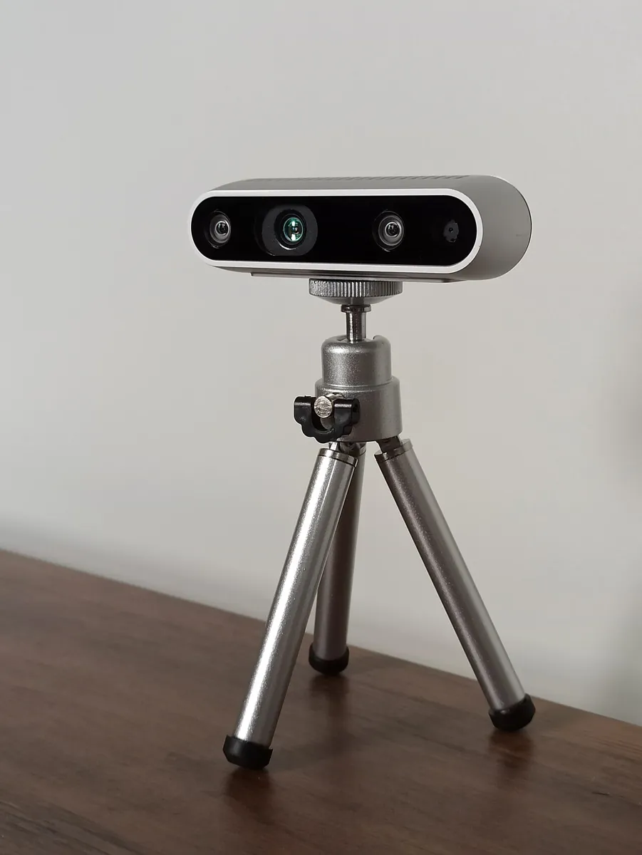
Robots: stereo depth helps robots find the relative position of 3D objects around them, and separate objects that overlap in the image — one chair in front of another — which colour alone cannot do.
- Mapping: stereo photos from aircraft and satellites are used for contour maps and 3D building models.
- Active stereo: projecting a light or laser pattern onto the scene makes matching easier on plain surfaces.
- Picking from piles: a point cloud shows which object is on top — the one the arm should pick first.
Think
Think about it
Think
Your stereo rig has B = 60 mm. To pick blocks 1.5 m away with the same depth accuracy you now get at 0.75 m, roughly how wide must the baseline be (same cameras)?
Experiment
Try it in the lab
About 45 minutes. The Python part needs only NumPy and OpenCV; the optional real stereo part needs two identical webcams on a rigid strip. Bench part: Arduino UNO, 3 LEDs, 3 × 220 Ω.
Experiment
Measure depth and test its limits
You will need
- `stereo_depth_lab.py` (opencv-python, numpy; pyserial for the LEDs)
- Depth vision explorer (browser)
- Optional: two identical webcams, an aluminium strip, the Lesson 12 checkerboard
- Bench: Arduino UNO, red/green/yellow LEDs, 3 × 220 Ω, breadboard, jumpers
Steps
- Run the script. Change B from 60 to 120 mm (and the disparity range to match). What happens to the error table?
- Raise the camera noise from 4 to 20. Which region breaks first — the blocks or the grey sheet?
- Change `blockSize` from 7 to 3 and to 15. Which is sharper at block edges, and which is smoother?
- In the depth explorer, find the distance where the depth error crosses 10 mm for your settings.
- Bench: send `Z 300`, `Z 500` and `Z 800` from the Serial Monitor, then stop sending and watch the timeout.
Interactive · Depth vision explorer · Educational
Z ≈ (f·b)/d recovers camera-frame depth; align RGB+(u,v)+Z → XYZ, then TF to base for Stage 8 IK. Synthetic depth only — not a depth camera / not OpenCV stereo.
- Wider baseline → bigger disparities → smaller depth error, but a bigger blind strip at the edge.
- Plain areas give confident-looking but unreliable depth.
- Small blocks smear at edges; big blocks are smooth but blur object boundaries.
Knowledge check
Check your understanding
Knowledge check
1. With f = 700 px and B = 60 mm, a disparity of 70 px means Z =
2. If the distance doubles, the stereo depth error becomes about…
3. Why are stereo images rectified before matching?
4. Which surface is hardest for passive stereo?
5. What does a point cloud give the arm that a table homography cannot?
Mini assignment
Hands-on assignment
Mini assignment
A depth map of the lab table
Use the synthetic lab (and two real webcams if you have them) to measure block heights and drive the reach-zone lights.
Deliverables
- A disparity image and a short note on where depth is missing and why.
- A table of 3 objects: true height, measured height (table Z − top Z).
- Your error-vs-distance table for two different baselines.
- A 20-second video of the reach-zone LEDs changing as a block moves nearer and farther.
Do this, step by step
- Run
stereo_depth_lab.pyand save the disparity image; note where depth is missing. - Measure 3 objects: height = table Z − top Z, and compare with the true height.
- Run again with two different baselines and fill an error-vs-distance table.
- Upload
reach_zone.inoand sendZvalues while a block moves nearer and farther. - Record a 20-second video of the reach-zone LEDs.
Stuck? Hints, one at a time
- Z = f·B/d: a bigger baseline B gives a bigger disparity and a smaller error at the same distance.
- Plain, textureless areas (like the grey sheet) give no disparity — that is missing depth, not zero depth.
- Depth error grows with Z², so measure heights close to the camera first.
Challenges (pick by level)
- 🟢 Beginner: Compute disparity by hand for Z = 400, 800 and 1600 mm with f = 700 px and B = 60 mm.
- 🟡 Intermediate: Add a third block to the synthetic scene and report its height from the point cloud.
- 🟠 Advanced: Find the tallest object in the point cloud and send its (X, Y, Z) top point to the Serial Monitor.
- 🔴 Expert: Calibrate two real webcams with
cv.stereoCalibrate, rectify them, and measure a block’s distance at 40, 60 and 80 cm against a tape. - ⚫ Research: Project a random-dot pattern onto a plain sheet with a phone or projector and measure how much of the sheet gets valid depth with and without it (a home-made active stereo).
Next step
Depth tells the arm *where* an object is. To grasp it, the arm also needs to know how the object is *turned*. In Lesson 15 — Object Pose Estimation you find an object’s full 6-DOF pose with solvePnP.
Sources
- OpenCV 4.x — Depth Map from Stereo Images — disparity = x − x′ = Bf/Z,
StereoBM, and the matcher parameters (number of disparities, min disparity, uniqueness ratio, speckle filtering, texture threshold). - Wikipedia — Computer stereo vision — undistortion, rectification, disparity maps inversely proportional to depth, point clouds, active stereo with structured light or laser, and uses in robotics and mapping.
- Photos: Wikimedia Commons (credits under each image).
Look back: Lesson 13: Perspective & Projection. Next: Lesson 15: Object Pose Estimation. Related: Stage 11 — Computer Vision, Stage 13 — Perception, Planning & Manipulation.
Self-attested for now — keep artifacts in your lab notebook.
Complete
Today's goal
0 of 1 done today
Mark this lesson complete when you have worked the experiment, knowledge check, and assignment (even roughly).