
Electronics & Embedded Systems · Lesson 09
PWM & Motor/Servo Control
Est. 50–65 min
Why
Why your robot needs “how much” on the output side
In Lesson 8 your robot learned to measure “how much” coming in. Now it needs “how much” going out: how fast should the wheel spin, how far should the elbow turn? A microcontroller pin can only be fully ON or fully OFF. PWM (pulse-width modulation) is the trick that turns that simple switch into a smooth “how much” — by switching very fast and changing how long it stays ON.
By the end you will be able to: explain duty cycle, period and frequency; turn an analogWrite() value into a duty and an average voltage; say where the Uno’s 490 Hz and 980 Hz come from; drive a DC motor’s speed through a driver (never from a pin); command a hobby servo with 1–2 ms pulses using the Servo library; calibrate a servo’s end points safely; plan servo power with a current budget and capacitors; and add soft limits and slew limiting so an arm never jumps or crashes.
Concept
PWM in plain words: a very fast switch
Think of a ceiling fan’s old-style regulator replaced by a person flicking the switch ON and OFF very fast. If they keep it ON for three-quarters of every second and OFF for a quarter, the fan settles at a steady, slower speed — it is too heavy to follow each flick. That is PWM. The pin only ever gives 0 V or 5 V, but a slow load — a motor, a heater, or your eye looking at an LED — feels the average.
Three words: period, frequency, duty cycle
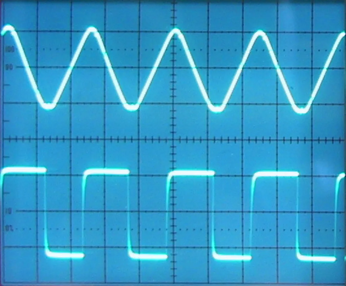
SparkFun’s PWM tutorial defines the duty cycle as the percentage of time a digital signal is ON over one period, and the period as the inverse of the frequency. A 50% duty signal is ON half the time and looks like an ideal square wave. 100% duty is the same as a steady HIGH; 0% is the same as ground. Arduino’s “Basics of PWM” page adds that the ON time is called the pulse width — changing (modulating) that width is what gives the technique its name.
duty = t_on ÷ T V_average = duty × V_high T = 1 ÷ f
- t_on = time the signal is HIGH in one period, T = period, f = PWM frequency
- Uno: V_high = 5 V. analogWrite(pin, 127) → duty ≈ 50% → average ≈ 2.5 V
- The average only means something to a load that is slower than the PWM (a motor, an LED seen by an eye)
analogWrite(): PWM in one line
Arduino’s analogWrite(pin, value) sets a duty from 0 (always off) to 255 (always on). After the call the pin keeps producing that steady rectangular wave until the next analogWrite(), digitalRead() or digitalWrite() on the same pin. You don’t need pinMode() first, and despite the name it has nothing to do with the analog pins or analogRead(). Only some pins can do it — on the Uno they are marked with a ~ tilde.
| Board | PWM pins | PWM frequency |
|---|---|---|
| UNO R3 and earlier, Nano, Mini | 3, 5, 6, 9, 10, 11 | 490 Hz (pins 5 and 6: 980 Hz) |
| UNO R4 Minima / WiFi | 3, 5, 6, 9, 10, 11 | 490 Hz |
| Mega | 2–13, 44–46 | 490 Hz (pins 4 and 13: 980 Hz) |
Where 490 Hz and 980 Hz come from
Arduino’s “Secrets of Arduino PWM” explains that the ATmega328P has three timers (Timer 0, 1 and 2), each driving two PWM outputs — six in total, which matches the datasheet’s “Six PWM Channels”. The Arduino core divides the 16 MHz clock by 64 for all three. Timer 0 (pins 5 and 6) runs in fast PWM, counting 0 → 255: 16 MHz ÷ 64 ÷ 256 ≈ 976.6 Hz. Timers 1 and 2 (pins 9, 10, 3 and 11) run in phase-correct PWM, counting up and back down: 16 MHz ÷ 64 ÷ 255 ÷ 2 ≈ 490.2 Hz. Timer 0 also drives millis() and delay() — which is why the reference warns that pins 5 and 6 give slightly higher duty than expected at very low values, and why you must not change Timer 0’s frequency.
DC motors
Driving a DC motor: PWM sets the speed, the driver supplies the current
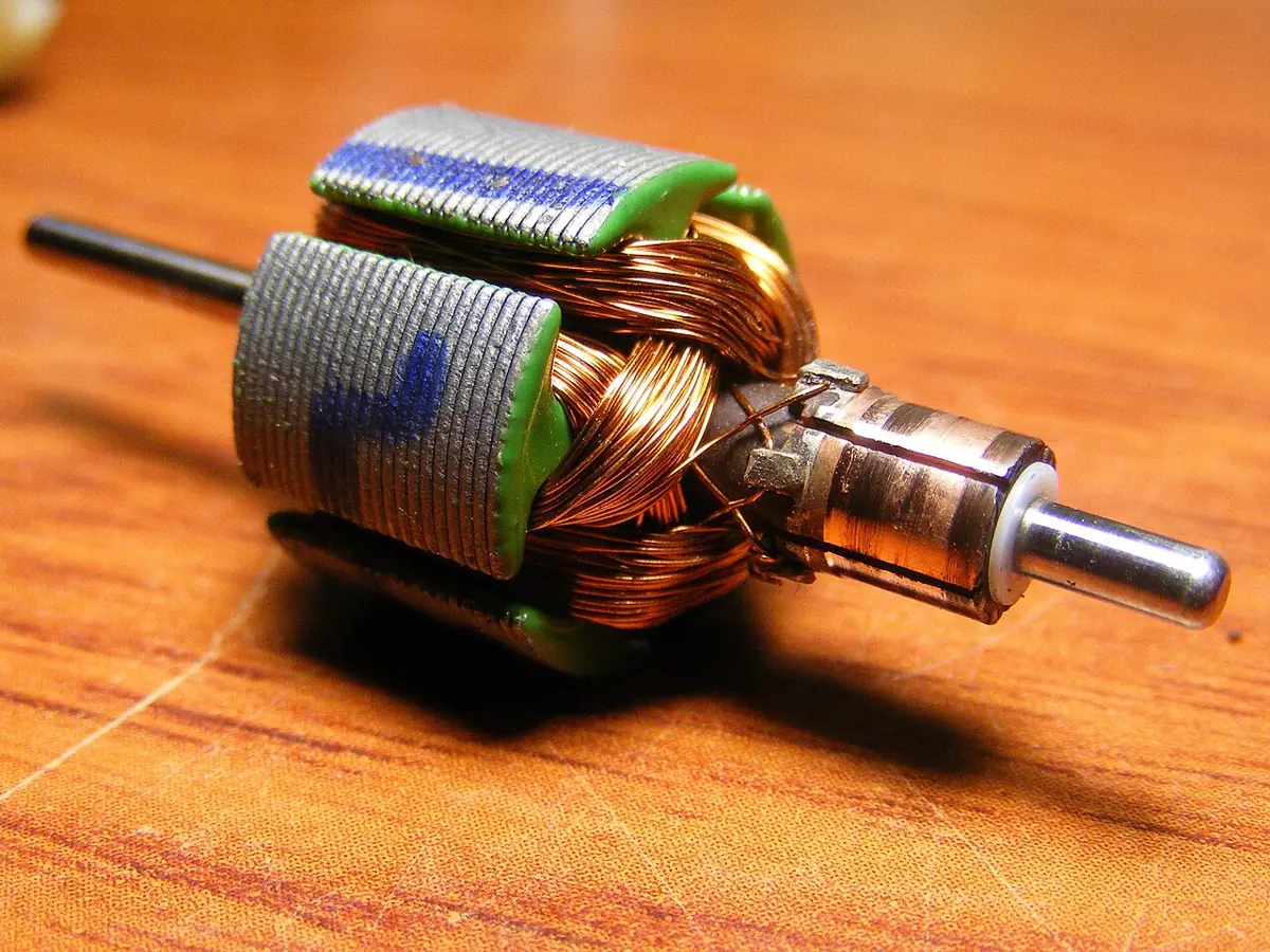
A brushed DC motor turns when current flows through its windings. Give it a higher average voltage and it spins faster (under the same load). So PWM is a natural speed control — but the pin must never carry the motor current. The ATmega328P datasheet lists an absolute maximum of 40 mA per I/O pin and 200 mA through the chip’s VCC and GND pins; the UNO R4’s datasheet says its GPIOs can safely handle only 8 mA. A small hobby motor can draw far more than that, especially when it starts or stalls.
| Wrong | Right — and when to use it |
|---|---|
| Motor between a pin and GND | Logic-level MOSFET low-side switch + flyback diode (Lesson 6): one direction, PWM on the gate for speed |
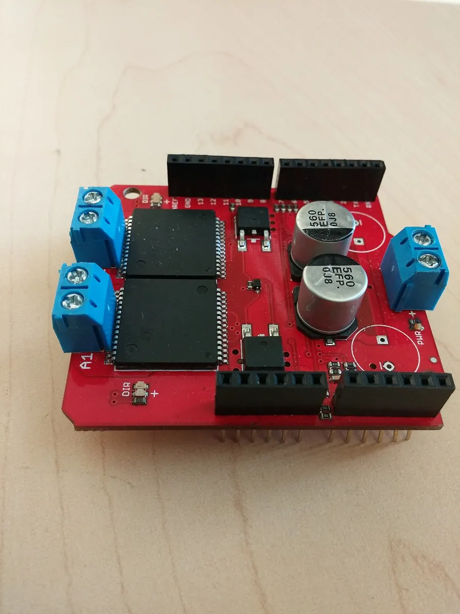
| Reversing a motor by swapping wires by hand | H-bridge driver (chip, shield or module): PWM for speed plus direction pins, both ways |
| Motor powered from the Arduino 5V pin | Separate motor supply sized for the stall current; join its ground to the Arduino GND |
Signal
Arduino PWM pin → driver’s PWM/enable input. Direction pins → driver’s direction inputs (H-bridge).
Power
Motor supply (+) → driver’s motor power input. Never the Arduino 5V pin.
Ground
Motor supply (−) → driver GND → Arduino GND. One shared reference, or the signal means nothing.
Protection
Flyback diodes (if the driver doesn’t have them), a fuse or current-limited supply, and a capacitor across the motor supply.
Servos
Hobby servos: the pulse width is the command
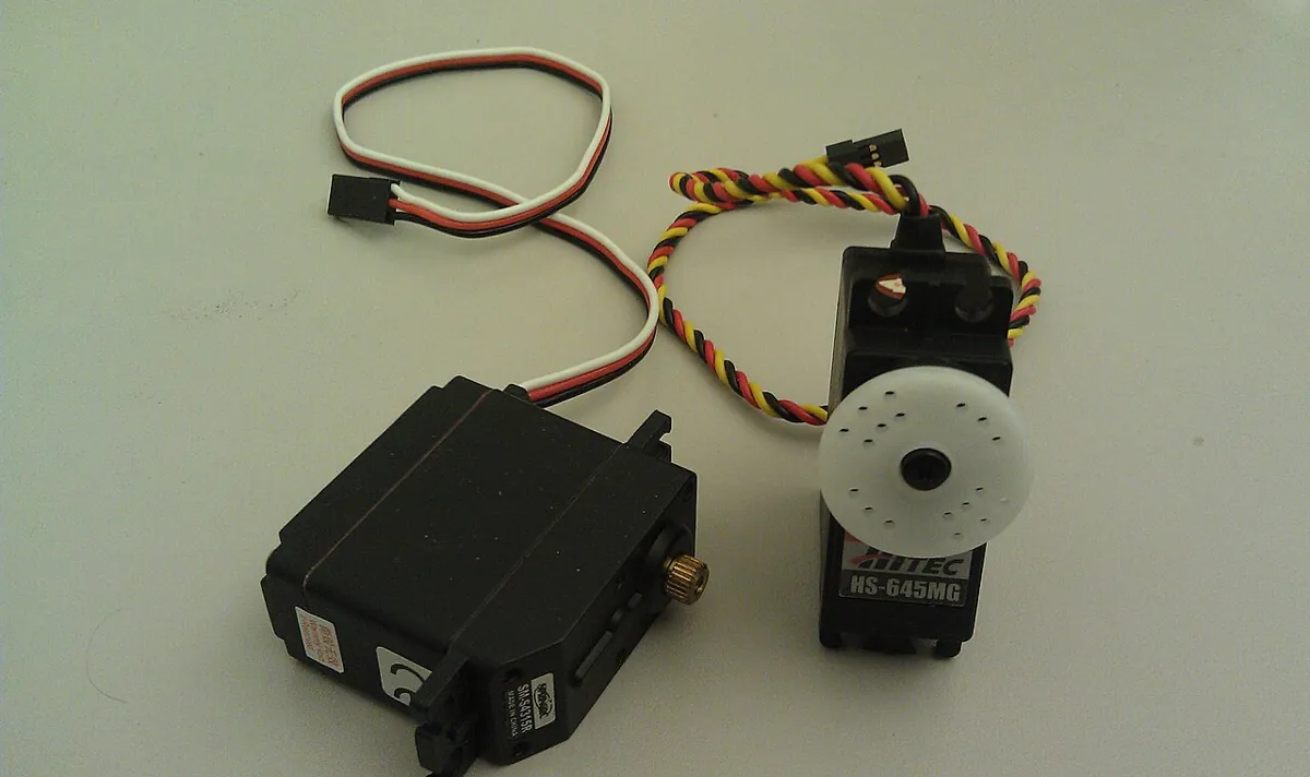
A hobby servo is a small DC motor, a gearbox, a potentiometer on the output shaft and a little control board, all in one box. SparkFun’s servo tutorial explains the loop: the board measures the incoming pulse, compares it with the pot’s position, and drives the motor until they match. That is feedback — the servo does its own position control, so your code only has to send the target.
The target is sent as a pulse every 20 ms (50 Hz), between 1 and 2 ms wide; about 1.5 ms is the centre (SparkFun). SparkFun calls the 1–2 ms range a convention rather than a hard standard — some servos move further with shorter or longer pulses, and some are mechanically limited to about 90°. Arduino’s Servo library default is wider: attach(pin) maps 0° to 544 µs and 180° to 2400 µs.
| Call | What it does | Watch out |
|---|---|---|
| servo.attach(pin) | Starts pulses on a pin; 0° = 544 µs, 180° = 2400 µs by default | On an Uno it uses Timer 1, so analogWrite() stops working on pins 9 and 10 |
| servo.attach(pin, min, max) | Same, with your calibrated pulse range in µs | Find min and max slowly, stopping before the hard stop |
| servo.write(angle) | Sets the angle 0–180 (speed and direction on a continuous servo; ~90 = stop) | On AVR, values above the pulse threshold are taken as µs |
| servo.writeMicroseconds(us) | Sets the pulse directly: 1000 one end, 1500 middle, 2000 other end on a standard servo | Some servos respond 700–2300; pushing past the end (a growling sound) is high current |
| servo.read() | Returns the last angle you wrote | It is NOT the real shaft angle — a servo cannot report it |
The library header explains the pin-9/10 rule: PWM via analogWrite() is disabled on the pins tied to the timer the library uses, as soon as the first servo is attached. On an Uno that timer is Timer 1, whose outputs are pins 9 and 10 (see the timer table in “Secrets of Arduino PWM”). One timer can serve up to 12 servos.
| Wire | Usual colours |
|---|---|
| Ground (−) | Black or brown |
| Power (+) | Red |
| Signal | Yellow, orange or white |
Power
Power: the part that decides whether your arm works
Arduino’s “Servo Motor Basics” gives a real example: a small Feetech mini servo needs 4.8–6 V and only 5–6 mA when idle, but its current can reach up to 800 mA when it moves under load — “generally not safe to draw from an Arduino board”. Their advice: an external supply, checked against the servo’s operating voltage, idle, running and stall current; a 100 µF capacitor for that servo; and a reminder that USB ports are limited to 500 mA (USB 2.0) or 900 mA (USB 3.0).
Adafruit is just as clear: even micro servos draw several hundred mA when moving, some high-torque servos draw more than 1 A each, and using the Arduino 5V pin for servos causes electrical noise and brownouts that make the board act erratically, reset or overheat — exactly Meera’s problem. SparkFun adds two habits: a straining servo makes the supply sag (and can reset microcontrollers), and with several servos you should give each one its own heavy wire back to the supply (star power) instead of daisy-chaining.
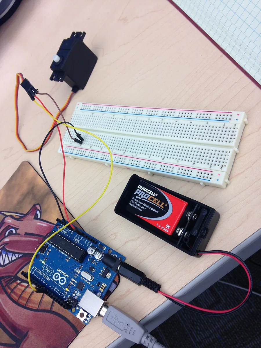
Many servos: use a servo driver
Adafruit’s 16-channel 12-bit PWM/servo driver (built on the PCA9685 chip) drives up to 16 servos over I2C using only two Arduino pins, with no extra processing on the Arduino. Its guide separates two supplies: VCC powers only the chip (3.3 V or 5 V logic); V+ feeds the servos (up to 6 V) — through the blue terminal block, which is polarity-protected. All 16 channels share one PWM frequency (servos about 50–60 Hz; setPWMFreq() accepts 40–1600 Hz), the default I2C address is 0x40, and for a capacitor the guide suggests n × 100 µF as a starting point, n being the number of servos (for example 470 µF or more for five).
| Supply | Notes |
|---|---|
| 5 V 2 A switching supply | A few small servos |
| 5 V 10 A switching supply | A full arm with headroom |
| 4 × AA holder | 6 V with alkaline cells, 4.8 V with NiMH |
| 4.8 or 6 V RC battery pack | Mobile robots |
Visual
Visualise it: PWM to a driver, pulses to a servo
Stay on **Safe: PWM → driver → motor** and drag the duty slider: the motor spins faster as the duty rises, because the driver turns the MCU’s logic-level PWM into motor current. Drag the servo angle from 0° to 180° — in real life that angle becomes a 1–2 ms pulse every 20 ms. Then click **Bad: GPIO-direct motor** once to see why a pin can never supply motor current. Browser simulation only — no real pins are touched.
Interactive · Motor & Servo Bench
Compare a safe path (PWM → driver → motor, common ground, separate power) vs the dangerous habit of driving a motor from a bare GPIO pin. Simulated only.
DC motor (via driver)
Driver handles current. MCU only sends logic-level PWM. Common ground required.
Servo (pulse width)
Servo needs dedicated 5–6 V power + signal from MCU. Soft limits before multi-joint arms.
Code lab
Code lab: duty, timers, pulses and a power budget in Python
1. The PWM toolkit
This script turns analogWrite() values into duty and average voltage, recalculates the Uno’s two PWM frequencies from the 16 MHz clock, draws a PWM period as text, compares servo pulses for the 1000–2000 µs convention and the Servo library’s 544–2400 µs default, and converts microseconds to PCA9685 ticks.
# pwm_toolkit.py — duty cycle, average voltage, Uno PWM frequencies and servo pulse maths.
# Stage 4, Lesson 9. Simulation only: arithmetic and prints. No pins, no hardware.

F_CPU = 16_000_000      # Uno R3 system clock (16 MHz crystal)
PRESCALER = 64          # Arduino core sets all three timers to divide by 64


def duty_from_value(value):
    """analogWrite(pin, value): value 0..255 -> fraction of time HIGH."""
    return value / 255


print("1) analogWrite() value -> duty cycle -> average voltage (5 V pin)")
print("-" * 70)
for value in (0, 64, 127, 191, 255):
    d = duty_from_value(value)
    print(f"  analogWrite({value:3d}) -> duty {d*100:5.1f}% -> average {d*5.0:4.2f} V")
print("  The pin is only ever 0 V or 5 V. 'Average' is what a slow load (motor, eye) feels.")

print()
print("2) Where 490 Hz and 980 Hz come from (ATmega328P timers, prescaler 64)")
print("-" * 70)
fast = F_CPU / PRESCALER / 256            # Timer0, fast PWM: counts 0..255
phase = F_CPU / PRESCALER / 255 / 2       # Timer1/2, phase-correct: counts up and down
for name, f in (("Timer0 fast PWM (pins 5, 6)", fast),
                ("Timer1/2 phase-correct (pins 9, 10, 3, 11)", phase)):
    print(f"  {name:<44} {f:9.3f} Hz, period {1000/f:5.3f} ms")

print()
print("3) One PWM period at 490 Hz, drawn as 20 slices (# = HIGH)")
print("-" * 70)
for value in (51, 127, 204):
    high = round(duty_from_value(value) * 20)
    on_us = duty_from_value(value) * 1e6 / phase
    print(f"  value {value:3d}: [{'#'*high}{'.'*(20-high)}] HIGH for {on_us:6.0f} us of {1e6/phase:5.0f} us")

print()
print("4) Hobby servo: pulse width -> angle (50 Hz frame = 20 ms)")
print("-" * 70)


def pulse_for(angle, us_min, us_max):
    return us_min + (us_max - us_min) * angle / 180


print("  angle   1000-2000 us convention   Servo library defaults (544-2400 us)")
for angle in (0, 45, 90, 135, 180):
    a = pulse_for(angle, 1000, 2000)
    b = pulse_for(angle, 544, 2400)
    print(f"  {angle:4d}°   {a:6.0f} us ({a/20000*100:4.1f}% duty)    {b:6.0f} us ({b/20000*100:4.1f}% duty)")
print("  Same angle, different pulse: always calibrate YOUR servo's end points gently.")

print()
print("5) PCA9685 driver: microseconds -> 12-bit ticks (4096 per period)")
print("-" * 70)
for freq in (50, 60):
    tick_us = 1e6 / freq / 4096
    print(f"  {freq} Hz: period {1e6/freq:7.1f} us, one tick = {tick_us:5.2f} us")
    for us in (1000, 1500, 2000):
        print(f"      {us} us -> {round(us / tick_us):4d} ticks")
Output (run with python3 pwm_toolkit.py)
1) analogWrite() value -> duty cycle -> average voltage (5 V pin)
----------------------------------------------------------------------
  analogWrite(  0) -> duty   0.0% -> average 0.00 V
  analogWrite( 64) -> duty  25.1% -> average 1.25 V
  analogWrite(127) -> duty  49.8% -> average 2.49 V
  analogWrite(191) -> duty  74.9% -> average 3.75 V
  analogWrite(255) -> duty 100.0% -> average 5.00 V
  The pin is only ever 0 V or 5 V. 'Average' is what a slow load (motor, eye) feels.

2) Where 490 Hz and 980 Hz come from (ATmega328P timers, prescaler 64)
----------------------------------------------------------------------
  Timer0 fast PWM (pins 5, 6)                    976.562 Hz, period 1.024 ms
  Timer1/2 phase-correct (pins 9, 10, 3, 11)     490.196 Hz, period 2.040 ms

3) One PWM period at 490 Hz, drawn as 20 slices (# = HIGH)
----------------------------------------------------------------------
  value  51: [####................] HIGH for    408 us of  2040 us
  value 127: [##########..........] HIGH for   1016 us of  2040 us
  value 204: [################....] HIGH for   1632 us of  2040 us

4) Hobby servo: pulse width -> angle (50 Hz frame = 20 ms)
----------------------------------------------------------------------
  angle   1000-2000 us convention   Servo library defaults (544-2400 us)
     0°     1000 us ( 5.0% duty)       544 us ( 2.7% duty)
    45°     1250 us ( 6.2% duty)      1008 us ( 5.0% duty)
    90°     1500 us ( 7.5% duty)      1472 us ( 7.4% duty)
   135°     1750 us ( 8.8% duty)      1936 us ( 9.7% duty)
   180°     2000 us (10.0% duty)      2400 us (12.0% duty)
  Same angle, different pulse: always calibrate YOUR servo's end points gently.

5) PCA9685 driver: microseconds -> 12-bit ticks (4096 per period)
----------------------------------------------------------------------
  50 Hz: period 20000.0 us, one tick =  4.88 us
      1000 us ->  205 ticks
      1500 us ->  307 ticks
      2000 us ->  410 ticks
  60 Hz: period 16666.7 us, one tick =  4.07 us
      1000 us ->  246 ticks
      1500 us ->  369 ticks
2000 us -> 492 ticks2. A power budget for a 6-servo arm
This script adds up idle, moving and stalled currents (with example numbers — replace them with your servos’ datasheet values), checks which supply survives the worst case with 25% headroom, applies Adafruit’s n × 100 µF capacitor rule, clamps commands to soft limits and slews a joint gently instead of letting it jump.
# servo_budget.py — power budget, capacitor rule of thumb, soft limits and slew limiting
# for a small 6-servo arm. Stage 4, Lesson 9. Simulation only: no pins, no hardware.
#
# CURRENT NUMBERS BELOW ARE EXAMPLES. Replace them with the figures from YOUR servo's datasheet
# (idle, running and stall current). Arduino's servo guide quotes a small Feetech mini servo at
# 5-6 mA idle and up to 800 mA; Adafruit warns high-torque servos can draw more than 1 A each.

servos = [  # name, idle mA, moving mA, stall mA  (example values only)
    ("base",     6, 400, 1500),
    ("shoulder", 6, 500, 1500),
    ("elbow",    6, 500, 1500),
    ("wrist1",   6, 250, 800),
    ("wrist2",   6, 250, 800),
    ("gripper",  6, 250, 800),
]

print("1) Current budget (example servo figures)")
print("-" * 70)
idle = sum(s[1] for s in servos)
moving = sum(s[2] for s in servos)
stall2 = moving - servos[1][2] - servos[2][2] + servos[1][3] + servos[2][3]
print(f"  All idle:                       {idle:5d} mA")
print(f"  All moving together:            {moving:5d} mA")
print(f"  Moving, shoulder+elbow stalled: {stall2:5d} mA   <- design for this, not the idle number")

print()
print("2) Which supply survives the worst case? (add 25% headroom)")
print("-" * 70)
need = stall2 * 1.25
for name, ma in (("USB 2.0 port", 500), ("USB 3.0 port", 900), ("5 V 2 A adapter", 2000),
                 ("5 V 4 A adapter", 4000), ("5 V 10 A supply", 10000)):
    verdict = "OK" if ma >= need else "too small"
    print(f"  {name:<18} {ma:6d} mA  vs need {need:6.0f} mA -> {verdict}")

print()
print("3) Bulk capacitor starting point (Adafruit: n x 100 uF)")
print("-" * 70)
print(f"  {len(servos)} servos -> start around {len(servos)*100} uF on the servo rail, rated above the rail voltage")

print()
print("4) Soft limits: clamp every command before it reaches the servo")
print("-" * 70)
LIMITS = {"elbow": (20, 160)}  # degrees; measure your own arm's safe range
for target in (-10, 0, 90, 170, 200):
    lo, hi = LIMITS["elbow"]
    safe = max(lo, min(hi, target))
    note = "" if safe == target else "  (clamped)"
    print(f"  elbow command {target:4d}° -> sent {safe:3d}°{note}")

print()
print("5) Slew limiting: move at most 3° per 20 ms update instead of jumping")
print("-" * 70)
pos, goal, step = 30, 75, 3
t = 0
line = []
while pos != goal:
    pos += max(-step, min(step, goal - pos))
    t += 20
    line.append(pos)
print("  positions:", " ".join(str(p) for p in line))
print(f"  reached {goal}° in {t} ms instead of one sudden jump (less current spike, less jerk)")
Output (run with python3 servo_budget.py)
1) Current budget (example servo figures)
----------------------------------------------------------------------
  All idle:                          36 mA
  All moving together:             2150 mA
  Moving, shoulder+elbow stalled:  4150 mA   <- design for this, not the idle number

2) Which supply survives the worst case? (add 25% headroom)
----------------------------------------------------------------------
  USB 2.0 port          500 mA  vs need   5188 mA -> too small
  USB 3.0 port          900 mA  vs need   5188 mA -> too small
  5 V 2 A adapter      2000 mA  vs need   5188 mA -> too small
  5 V 4 A adapter      4000 mA  vs need   5188 mA -> too small
  5 V 10 A supply     10000 mA  vs need   5188 mA -> OK

3) Bulk capacitor starting point (Adafruit: n x 100 uF)
----------------------------------------------------------------------
  6 servos -> start around 600 uF on the servo rail, rated above the rail voltage

4) Soft limits: clamp every command before it reaches the servo
----------------------------------------------------------------------
  elbow command  -10° -> sent  20°  (clamped)
  elbow command    0° -> sent  20°  (clamped)
  elbow command   90° -> sent  90°
  elbow command  170° -> sent 160°  (clamped)
  elbow command  200° -> sent 160°  (clamped)

5) Slew limiting: move at most 3° per 20 ms update instead of jumping
----------------------------------------------------------------------
  positions: 33 36 39 42 45 48 51 54 57 60 63 66 69 72 75
  reached 75° in 300 ms instead of one sudden jump (less current spike, less jerk)
Simulator
Try it in the simulator
Simulator · Electronics
PWM duty cycle → servo angle & LED brightness
One PWM signal, two loads: average voltage and LED brightness follow the duty cycle; a servo reads the pulse width.
Loading simulator…
Formulas used
- T = 1 / f
- t_high = D·T
- V_avg = D·V_high
- angle = (t_high − t_min) / (t_max − t_min) · range
Model & limits
Ideal square wave. Servo endpoints (t_min, t_max, range) differ between models, so they are adjustable; check yours.
Want to draft this circuit? Open Station Engine (a drafting workbench, no simulation yet).
Real world
Where PWM moves real robots
- Robot arms: hobby-servo arms (like this course’s 6-DOF arm) send one pulse train per joint, often from a PCA9685-style driver so the MCU stays free for sensors and safety checks.
- Wheeled robots: an H-bridge driver turns PWM into wheel speed and direction pins into forward/reverse.
- RC models: hobby servos were born here — moving rudders, flaps and steering from a radio receiver’s pulses.
- Fans and pumps: PWM sets airflow and flow rate without wasting power as heat the way a resistor would.
- LEDs and displays: PWM dims LEDs and mixes RGB colours — SparkFun’s tutorial shows both.
- Factory cells: big industrial servo drives use the same ideas — command signal, separate power stage, feedback, limits — at a much larger scale.
Bench build
Bench build: a knob-controlled servo that can’t crash or brown out
You need an Uno (or compatible), one small hobby servo, a 10 kΩ potentiometer, a separate 5 V supply (a 5 V 2 A adapter or a 4 × AA pack), a 100 µF electrolytic capacitor rated above the supply voltage, jumper wires and a multimeter. Check your servo’s datasheet for its voltage range before you connect anything.
Servo supply first
Supply (+) to servo red, supply (−) to servo black/brown. Capacitor across the supply near the servo: + to +, − to −.
Common ground
One wire from the supply (−) to an Arduino GND pin.
Signal
Servo yellow/orange to pin 9. That is the only servo wire that touches the Arduino’s headers.
Knob
Pot outer legs to Arduino 5V and GND, wiper to A0.
Meter check
Power off: no short between supply + and −. Power on: measure the servo supply — it should match its rating.
Upload and test
Open the Serial Monitor at 9600 baud. Turn the knob slowly; the servo follows, never past 20° or 160°, and never jumps.
// servo_knob_safe.ino — one servo follows a knob, with soft limits and gentle (slew-limited) motion
// (Stage 4, Lesson 9). For a REAL board on your bench. This sketch is not run inside the browser.
//
// WIRING — read twice before powering anything:
//   Servo RED   (+)    -> separate 5 V supply (+)   e.g. a 5 V 2 A adapter or 4 x AA pack (6 V)
//   Servo BROWN/BLACK  -> separate supply (-)  AND  Arduino GND   (common ground: the signal needs it)
//   Servo ORANGE/YELLOW (signal) -> Arduino pin 9
//   Knob: 10 kOhm pot, outer legs to Arduino 5V and GND, middle (wiper) to A0
//   About 100 uF electrolytic across the servo supply (+ to +, - to -), close to the servo.
// NEVER power the servo from an I/O pin. Avoid the Arduino 5V pin for servos too: moving servos
// draw hundreds of mA and can brown out (reset) the board. Check your servo's datasheet for its
// voltage range and stall current, and choose a supply that can deliver it.

#include <Servo.h>

const int SERVO_PIN = 9;
const int KNOB_PIN = A0;
const int SAFE_MIN = 20;          // soft limits in degrees: measure YOUR joint's safe range first
const int SAFE_MAX = 160;
const int MAX_STEP = 3;           // at most 3 degrees per update
const unsigned long UPDATE_MS = 20;

Servo joint;
int current = 90;                 // start in the middle
unsigned long lastUpdate = 0;

void setup() {
  Serial.begin(9600);
  joint.attach(SERVO_PIN);        // library default pulse range 544-2400 us; calibrate with
                                  // joint.attach(SERVO_PIN, minUs, maxUs) once you know your servo
  joint.write(current);
}

void loop() {
  if (millis() - lastUpdate < UPDATE_MS) return;   // non-blocking: no delay()
  lastUpdate = millis();

  int raw = analogRead(KNOB_PIN);                  // 0..1023
  int target = map(raw, 0, 1023, 0, 180);
  target = constrain(target, SAFE_MIN, SAFE_MAX);  // soft limits

  int step = constrain(target - current, -MAX_STEP, MAX_STEP);  // slew limit
  current += step;
  joint.write(current);

  Serial.print("raw "); Serial.print(raw);
  Serial.print("  target "); Serial.print(target);
  Serial.print("  sent "); Serial.println(current);
}Debugging
Debugging: when motors and servos misbehave
| Symptom | Likely cause | Fix |
|---|---|---|
| Board resets when servos move | Servos on the Arduino 5V pin or USB; supply too weak (brownout) | Separate servo supply sized for stall current; bulk capacitor; common ground |
| Servo jitters or twitches randomly | No common ground; long signal wire next to motor wires; weak supply | Join grounds; shorten and separate wires; check supply voltage while moving |
| Servo growls at one end | Pulse beyond its mechanical end | Calibrate with attach(pin, min, max) or writeMicroseconds(); add soft limits |
| analogWrite() on pin 9 or 10 stopped working | The Servo library took Timer 1 | Move the PWM output to pin 3, 5, 6 or 11 |
| Motor hums but doesn’t turn at low duty | Too little average voltage to overcome friction | Start from a higher duty, then lower it; check the driver’s minimum |
| Very low duties on pin 5 or 6 look higher than asked | Timer 0 is shared with millis() and delay() (analogWrite() reference) | Use pin 3, 9, 10 or 11 for very low duties |
| Driver or MOSFET gets hot | Motor current too high for the part; no heatsink | Check the stall current against the driver’s rating; add cooling or a bigger driver |
Think
Think about it
Think
Arjun says: “At 100% duty the pin is HIGH all the time, so at 100% the Arduino is powering the motor.” Is he right? And what changes if the motor is wired straight to the pin instead of through a driver?
Experiment
Try it in the lab: duty, pulses and a power budget
Twenty-five minutes with the Motor & Servo Bench, the two Python scripts and your notebook. You will connect duty to speed, angle to pulse width, and servos to a supply that can really feed them.
Experiment
Duty, pulses and a power budget
You will need
- Motor & Servo Bench (below, runs in your browser)
- Notebook or a text file
- Optional: your laptop to run `pwm_toolkit.py` and `servo_budget.py`
Steps
- In the bench (safe mode), set the duty to 25%, 50% and 75%. For each, write the `analogWrite()` value (duty × 255) and the average voltage on a 5 V pin.
- Set the servo to 0°, 90° and 180°. For each, write the pulse width with the 1000–2000 µs convention and with the Servo library default (544–2400 µs). Check with `pwm_toolkit.py` part 4.
- Work out the period of 490 Hz and 980 Hz PWM. Which Uno pins give which?
- Switch to **Bad: GPIO-direct motor** once. In one sentence, write why it faults.
- Run `servo_budget.py`. Copy the worst-case current and the smallest supply that passes. Then put in the real numbers from your own servo’s datasheet if you have one.
- Write a three-line wiring rule for Meera’s arm: power, ground, signal.
Interactive · Motor & Servo Bench
Compare a safe path (PWM → driver → motor, common ground, separate power) vs the dangerous habit of driving a motor from a bare GPIO pin. Simulated only.
DC motor (via driver)
Driver handles current. MCU only sends logic-level PWM. Common ground required.
Servo (pulse width)
Servo needs dedicated 5–6 V power + signal from MCU. Soft limits before multi-joint arms.
PWM is a command: duty for a motor driver, pulse width for a servo. The current always comes from a separate supply through a driver or the servo’s own electronics, and everything shares one ground. Soft limits and slew limiting keep the motion safe even when a command is wrong.
Knowledge check
Check your understanding
Knowledge check
1. PWM duty cycle is…
2. On a 5 V Uno, `analogWrite(9, 191)` gives an average of about…
3. Why do Uno pins 5 and 6 run PWM at about 980 Hz while 9 and 10 run at about 490 Hz?
4. A standard hobby servo usually expects…
5. `servo.read()` returns…
6. After `servo.attach(9)` on an Uno, `analogWrite(10, 128)` does nothing. Why?
7. Which is the safe way to drive a small DC motor’s speed from an Arduino?
8. Meera’s Uno resets whenever two servos powered from its 5V pin move together. The best fix is…
9. On a PCA9685 servo driver board, the VCC pin…
10. A servo growls and gets warm at 0°. What should you do?
Mini assignment
Hands-on assignment
Mini assignment
A safe PWM plan for your robot
Plan, simulate and (if you have the parts) build the output side of one robot joint or wheel — a servo or a DC motor — and prove the pin only commands, the supply really can feed it, and the motion has limits.
Deliverables
- A wiring drawing with three clearly separate paths: signal (pin → driver/servo), power (supply → driver/servo) and the common ground.
- A current budget with idle, moving and stall current from a real datasheet (or the lesson’s example numbers, clearly labelled), and the supply you chose with headroom.
- For a servo: your calibrated min/max pulse (or the plan to find it), and your soft limits in degrees. For a motor: the driver you chose and why.
- Output of `pwm_toolkit.py` and `servo_budget.py` with your own values, and one sentence on what each result means.
- If you build it: a Serial Monitor screenshot from `servo_knob_safe.ino` and a meter reading of the servo rail while the servo moves.
- Half a page in your own words: “a pin can tell a motor what to do — it can never feed it”.
Do this, step by step
- Pick one joint or wheel: a hobby servo or a small DC motor.
- Draw three separate paths: signal (pin → driver/servo), power (supply → driver/servo), common ground.
- Fill the current budget (idle, moving, stall) and pick a supply with headroom.
- Run
pwm_toolkit.pyandservo_budget.pywith your numbers and paste outputs. - If you have parts: upload
servo_knob_safe.ino, servo on a separate 5–6 V supply, and measure the servo rail while it moves.
Stuck? Hints, one at a time
- Hint 1: Most hobby servos expect a pulse every 20 ms (50 Hz); about 1.0–2.0 ms covers the normal range, but calibrate your own servo’s min/max.
- Hint 2: Soft limits stop the servo short of its end stops (e.g. 10–170°) so it never buzzes against the stop and stalls.
- Hint 3: A DC motor needs a driver (H-bridge or MOSFET); the PWM pin only sets the duty cycle.
- Hint 4: If the servo rail dips below about 4.5 V while moving, the supply or wires are too weak — shorten/thicken wires or use a bigger supply.
Challenges (pick by level)
- 🟢 Easy: What duty and average voltage does
analogWrite(64)give on a 5 V pin? *Check:*pwm_toolkit.pypart 1. - 🟢 Easy: What is the period of 490 Hz PWM in milliseconds? *Hint:* T = 1 ÷ f.
- 🟡 Medium: With the Servo library default (544–2400 µs), what pulse does 60° give? *Hint:* 544 + (2400 − 544) × 60 ÷ 180.
- 🟡 Medium: Six servos, each up to 1 A when stalled, two may stall at once while the rest move at 400 mA. Size the supply with 25% headroom. *Hint:* edit
servo_budget.py. - 🟠 Hard-ish: Add a second knob and servo to
servo_knob_safe.ino, each with its own soft limits. Which pin can the second servo use? *Hint:* read the attach() section of the Servo library documentation, and remember which pins lose analogWrite(). - 🔴 Hard: Rewrite the bench sketch for a PCA9685 driver at 50 Hz using
writeMicroseconds()-style values converted to ticks. *Hint:*pwm_toolkit.pypart 5 and Adafruit’s calibration steps. - ⚫ Expert: Read the ATmega328P datasheet’s Timer/Counter1 chapter and explain how you would make a 50 Hz servo signal in hardware with 16-bit resolution. *Hint:* a TOP value set by ICR1, and a prescaler.
Next step
Your robot can now measure (Lesson 8) and move (this lesson). In Lesson 10 — Microcontrollers (MCUs) you will open up the chip that does all of this: its CPU, memory, timers and peripherals — and compare the ATmega328P with the UNO R4’s RA4M1, the ESP32, STM32 and more, using their real datasheets.
Tip: explain today’s chapter with the fan and the fast switch — the switch is the pin, the fan is the motor, and the wall socket (never the switch) is what really powers the fan.
Look back: Lesson 8: Analog Signals & ADC. Next: Lesson 10: Microcontrollers (MCUs). Related: Stage 0 — Actuators, Stage 2 — Python + Robot Control and later Stage 7 — Control Systems.
Sources
- Arduino reference: analogWrite() — 0–255 duty, PWM pins and frequencies per board, no pinMode needed, pins 5/6 note.
- Arduino: Basics of PWM — pulse width, period, about 500 Hz → 2 ms, tilde pins.
- Arduino: Secrets of Arduino PWM — three timers, prescaler 64, fast vs phase-correct, 976.5625 Hz and 490.196 Hz, timer-to-pin table, Timer 0 and millis().
- Arduino: Servo Motor Basics with Arduino — Feetech mini servo 5–6 mA idle, up to 800 mA, external supply, USB limits, 100 µF, wire colours.
- Arduino Servo library documentation and Servo.h — attach() 544/2400 µs defaults, write(), writeMicroseconds(), read(), 12 servos per timer, PWM disabled on the timer’s pins. Library page: docs.arduino.cc/libraries/servo.
- Arduino UNO R4 WiFi, its datasheet (PDF) and user manual — 8 mA per GPIO, never power servos from the 5 V pin.
- Microchip ATmega48A/PA/88A/PA/168A/PA/328/P datasheet — six PWM channels, two 8-bit and one 16-bit timer, 40 mA per I/O pin and 200 mA VCC/GND absolute maximum.
- Adafruit Learn: 16-Channel PWM/Servo Driver — PCA9685, 16 channels over I2C, 0x40, VCC vs V+, up to 6 V, power choices, n × 100 µF, 40–1600 Hz, calibrating SERVOMIN/SERVOMAX.
- SparkFun Learn: Pulse Width Modulation — duty cycle, period, 50 Hz servo signal, 1–2 ms.
- SparkFun Learn: Hobby Servo Tutorial — feedback pot, 20 ms / 1–2 ms, wire colours, star power, current under load, stripped gears.
- Photos: Wikimedia Commons (credits under each image).
Self-attested for now — keep artifacts in your lab notebook.
Complete
Today's goal
0 of 1 done today
Mark this lesson complete when you have worked the experiment, knowledge check, and assignment (even roughly).