
Computer Vision for Robotics (Vision Foundations) · Lesson 15
Object Pose Estimation
Est. 55–70 min
Why
Why this lesson matters
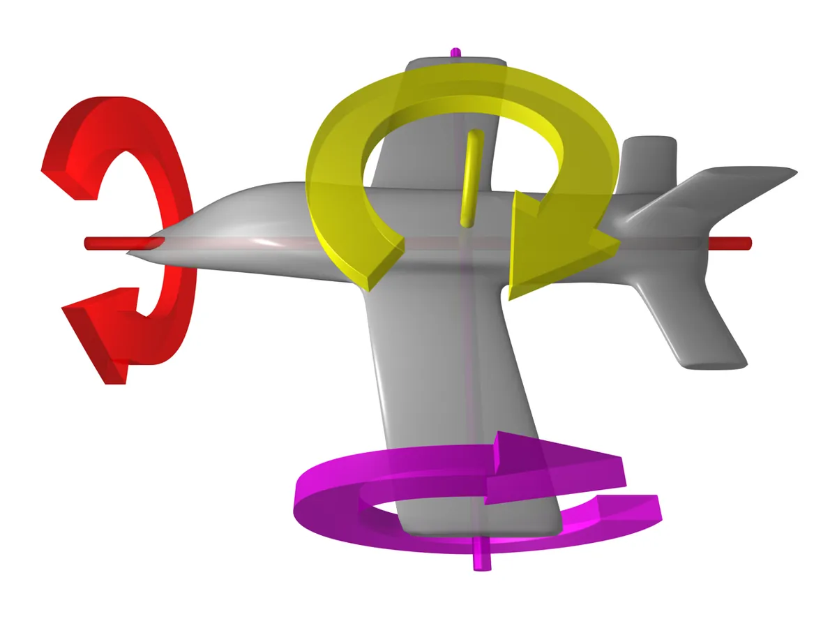
Think of putting a key into a lock. Knowing where the lock is (position) is not enough; you also have to turn the key to match the slot (orientation). A robot gripper is the same. A pose is position and orientation together: three numbers for where (x, y, z) and three for how it is turned (roll, pitch, yaw). That is why it is called a 6-DOF pose — six degrees of freedom.
In this lesson you use Perspective-n-Point (PnP): given some points whose 3D shape you know (the four corners of a printed marker), where they appear in the image, and your camera calibration from Lesson 12, cv.solvePnP finds the rotation and translation of the object relative to the camera. Then you move that pose into the robot’s base frame and turn it into a grasp the arm can actually use.
Concept
Where is it and how is it turned: 6-DOF pose from four corners
1. What a pose is
Every object gets its own little coordinate frame (its own x, y and z arrows). The pose of the object is the transform from object frame → camera frame: a rotation R (3×3) and a translation t (3 numbers, in the same unit you used for the object — we use mm). You met this 4×4 transform in Stage 10 (TF2). OpenCV writes the rotation compactly as a 3-number rotation vector rvec (axis × angle) and the translation as tvec; cv.Rodrigues(rvec) turns rvec back into the 3×3 matrix.
s · [u, v, 1]ᵀ = K · [R | t] · [X, Y, Z, 1]ᵀ
- X, Y, Z — a point in the object’s own frame (e.g. a marker corner, in mm)
- R, t — the pose we want: object frame → camera frame
- K — the camera matrix from Lesson 12 (fx, fy, cx, cy)
- u, v — where that point appears in the image (pixels); s — a scale factor
This is the same projection you used in Lesson 13, just run backwards: there you knew R and t and found pixels; here you know the pixels and find R and t. The OpenCV convention for the camera frame is: x to the right, y down, z forward out of the lens.
2. Why four corners are enough (and why markers help)
With three point pairs, PnP (called P3P) can have up to four answers. A fourth point removes most of the doubt, and the more points the better. Finding four reliable, numbered points on a random object is hard, so labs and factories often stick a fiducial marker on things. An ArUco marker is a square with a wide black border and a grid of black and white cells inside. The border makes it easy to find; the inner bits give it an ID and tell you which corner is which, even when the marker is rotated. One marker gives you all four corners you need.
Calibrate the camera
You need K and the distortion coefficients (Lesson 12). Pose is only as good as calibration.
Detect the marker
cv.aruco.ArucoDetector(dictionary, params).detectMarkers(img)returns the four corners of each marker (clockwise from top-left) and its ID.Describe the marker in 3D
For a marker of side L, the corners are (−L/2, L/2, 0), (L/2, L/2, 0), (L/2, −L/2, 0), (−L/2, −L/2, 0). The unit of L becomes the unit of tvec — measure the printed square with a ruler!
Solve PnP
cv.solvePnP(objPoints, corners, K, dist, flags=cv.SOLVEPNP_IPPE_SQUARE)returns rvec and tvec. IPPE_SQUARE is the method OpenCV’s docs recommend for a single square marker.Check it
Project the corners back with
cv.projectPointsand measure the reprojection error in pixels. Draw the axes withcv.drawFrameAxesand look.Move it to the robot
T_base_obj = T_base_cam · T_cam_obj (Stage 10 TF). Then pick a grasp: position, approach from above, and a gripper yaw that matches the block.
3. Where pose estimation goes wrong
| Problem | What you see | Why |
|---|---|---|
| Wrong marker size typed in | distance off by the same ratio, reprojection error still tiny | tvec is in the units of L; a 50 mm guess for a 40 mm print makes everything 1.25× farther |
| Square symmetry | yaw off by 90°, error still tiny | a plain square looks the same every 90°; the ArUco bits break this, a plain block does not |
| Flat-target ambiguity | tilt jumps between two values | a small or far flat square can fit two mirror-like poses almost equally well |
| Far away | pose jitters | a 13 px marker gives the solver very little to work with |
Visual
Visualise it: the pose estimator
Move the object’s yaw and position and change the detection confidence; watch the pose and the go/no-go gate before IK. Educational model — not OpenCV.
Interactive · Object pose estimator · Educational

Pose = position + orientation in the camera frame. Gate on confidence, transform to the arm base (TF / Stage 10), feed Stage 8 IK and Stage 9 trajectories. Teaching overlay only — not PnP/ArUco/OpenCV.
Code lab
Code lab: find two blocks, get their 6-DOF pose, choose a grasp
We render a synthetic top-down picture of the lab table with two blocks. Each block has a real 40 mm ArUco marker (DICT_4X4_50, IDs 3 and 7) on top, drawn with OpenCV’s own generateImageMarker. The camera is 600 mm above the table looking down. Because we made the picture, we know the true pose of each block and can check solvePnP honestly — and then try the classic mistakes.
"""
pose_estimation_lab.py  -  Stage 11, Lesson 15: Object Pose Estimation
AIHUB STATION, Kota.  Needs: pip install opencv-python numpy

We build a synthetic top-down picture of the lab table with two blocks.
Each block has a printed 40 mm ArUco marker (DICT_4X4_50) on top.
Because we made the picture, we KNOW the true pose of each block, so we can
check how good cv.solvePnP really is - and how it fails.
"""
import numpy as np
import cv2 as cv

rng = np.random.default_rng(15)
np.set_printoptions(precision=1, suppress=True)

# ---------- 1. Camera (from Lesson 12 calibration) ----------
W, H = 1280, 720
K = np.array([[800.0, 0, 640], [0, 800.0, 360], [0, 0, 1]])
dist = np.zeros(5)                      # image already undistorted
L = 40.0                                # marker side in mm (black border to black border)
BLOCK_H = 50.0                          # block height in mm (marker is stuck on top)

# Marker corners in the marker's own frame, in the order IPPE_SQUARE wants
OBJ = np.array([[-L/2,  L/2, 0], [ L/2,  L/2, 0],
                [ L/2, -L/2, 0], [-L/2, -L/2, 0]], dtype=np.float32)

def rot_z(deg):
    a = np.radians(deg); c, s = np.cos(a), np.sin(a)
    return np.array([[c, -s, 0], [s, c, 0], [0, 0, 1]])

def rot_x(deg):
    a = np.radians(deg); c, s = np.cos(a), np.sin(a)
    return np.array([[1, 0, 0], [0, c, -s], [0, s, c]])

def T(R, t):
    M = np.eye(4); M[:3, :3] = R; M[:3, 3] = t; return M

# Camera mounted 600 mm above the table, looking straight down.
# Camera x -> base -y, camera y -> base -x, camera z -> base -z (down)
R_base_cam = np.array([[0, -1, 0], [-1, 0, 0], [0, 0, -1]], dtype=float)
T_base_cam = T(R_base_cam, [300.0, 0.0, 600.0])

# True block poses in the ROBOT BASE frame: (x, y, yaw) on the table
truth = {3: (330.0, 60.0, 30.0), 7: (250.0, -80.0, -65.0)}

def T_base_marker(x, y, yaw):
    # marker lies flat on top of the block, its z axis pointing up
    return T(rot_z(yaw), [x, y, BLOCK_H])

# ---------- 2. Render the scene with real ArUco markers ----------
aruco_dict = cv.aruco.getPredefinedDictionary(cv.aruco.DICT_4X4_50)
img = np.full((H, W), 150, np.uint8)
img = cv.add(img, rng.integers(0, 25, (H, W), dtype=np.uint8))   # table texture
T_cam_base = np.linalg.inv(T_base_cam)
for mid, (x, y, yaw) in truth.items():
    T_cam_m = T_cam_base @ T_base_marker(x, y, yaw)
    # block top face (60 mm square, white) then the marker itself
    for side, tile in ((60.0, None), (L, cv.aruco.generateImageMarker(aruco_dict, mid, 240))):
        sq = np.array([[-side/2, side/2, 0], [side/2, side/2, 0],
                       [side/2, -side/2, 0], [-side/2, -side/2, 0]])
        pts, _ = cv.projectPoints(sq, cv.Rodrigues(T_cam_m[:3, :3])[0], T_cam_m[:3, 3], K, dist)
        pts = pts.reshape(4, 2).astype(np.float32)
        if tile is None:
            cv.fillConvexPoly(img, np.round(pts).astype(np.int32), 235)
        else:
            src = np.float32([[0, 0], [239, 0], [239, 239], [0, 239]])
            Hm = cv.getPerspectiveTransform(src, pts)
            warped = cv.warpPerspective(tile, Hm, (W, H), flags=cv.INTER_AREA)
            mask = cv.warpPerspective(np.full_like(tile, 255), Hm, (W, H))
            img[mask > 0] = warped[mask > 0]
img = cv.GaussianBlur(img, (3, 3), 0)
img = np.clip(img + rng.normal(0, 3, img.shape), 0, 255).astype(np.uint8)
cv.imwrite('pose_scene.png', img)

# ---------- 3. Detect markers and solve PnP ----------
detector = cv.aruco.ArucoDetector(aruco_dict, cv.aruco.DetectorParameters())
corners, ids, _ = detector.detectMarkers(img)
print('1) DETECT + solvePnP (IPPE_SQUARE), marker side 40 mm')
print(f'   markers found: {sorted(ids.flatten().tolist())}')

def reproj_err(obj, img_pts, rvec, tvec):
    p, _ = cv.projectPoints(obj, rvec, tvec, K, dist)
    return float(np.sqrt(np.mean(np.sum((p.reshape(-1, 2) - img_pts.reshape(-1, 2))**2, axis=1))))

def yaw_tilt(R):
    yaw = np.degrees(np.arctan2(R[1, 0], R[0, 0]))
    tilt = np.degrees(np.arccos(np.clip(R[2, 2], -1, 1)))
    return yaw, tilt

found = {}
for c, i in zip(corners, ids.flatten()):
    c = c.reshape(4, 2)
    ok, rvec, tvec = cv.solvePnP(OBJ, c, K, dist, flags=cv.SOLVEPNP_IPPE_SQUARE)
    err = reproj_err(OBJ, c, rvec, tvec)
    T_cam_m = T(cv.Rodrigues(rvec)[0], tvec.ravel())
    T_b = T_base_cam @ T_cam_m
    yaw, tilt = yaw_tilt(T_b[:3, :3])
    tx, ty, tyaw = truth[int(i)]
    found[int(i)] = (c, T_b)
    print(f'   id {i}: tvec (camera) = {tvec.ravel()} mm, reprojection error {err:.2f} px')
    print(f'         in base frame: x {T_b[0,3]:.1f}  y {T_b[1,3]:.1f}  z {T_b[2,3]:.1f} mm,'
          f' yaw {yaw:.1f} deg, tilt {tilt:.1f} deg')
    print(f'         truth:         x {tx:.1f}  y {ty:.1f}  z {BLOCK_H:.1f} mm, yaw {tyaw:.1f} deg'
          f'  -> position error {np.hypot(T_b[0,3]-tx, T_b[1,3]-ty):.1f} mm, yaw error {abs(yaw-tyaw):.1f} deg')

# ---------- 4. Mistakes that look fine ----------
print('\n2) MISTAKES')
c3 = found[3][0]
OBJ50 = OBJ * (50.0 / L)
ok, rv, tv = cv.solvePnP(OBJ50, c3, K, dist, flags=cv.SOLVEPNP_IPPE_SQUARE)
ok, rv0, tv0 = cv.solvePnP(OBJ, c3, K, dist, flags=cv.SOLVEPNP_IPPE_SQUARE)
print(f'   a) wrong marker size (typed 50 mm, real 40 mm): distance {tv0[2,0]:.0f} -> {tv[2,0]:.0f} mm,'
      f' reprojection error still {reproj_err(OBJ50, c3, rv, tv):.2f} px  <- error check cannot catch this!')
c_rolled = np.roll(c3, 1, axis=0)
ok, rv, tv = cv.solvePnP(OBJ, c_rolled, K, dist, flags=cv.SOLVEPNP_IPPE_SQUARE)
y_ok = yaw_tilt((T_base_cam @ T(cv.Rodrigues(rv0)[0], tv0.ravel()))[:3, :3])[0]
y_bad = yaw_tilt((T_base_cam @ T(cv.Rodrigues(rv)[0], tv.ravel()))[:3, :3])[0]
print(f'   b) corners rotated by one place: yaw {y_ok:.1f} -> {y_bad:.1f} deg,'
      f' reprojection error {reproj_err(OBJ, c_rolled, rv, tv):.2f} px  <- a square looks the same every 90 deg')
c_swapped = c3[[1, 0, 2, 3]]
ok, rv, tv = cv.solvePnP(OBJ, c_swapped, K, dist, flags=cv.SOLVEPNP_ITERATIVE)
print(f'   c) two corners swapped: reprojection error {reproj_err(OBJ, c_swapped, rv, tv):.1f} px  <- caught by the error check')

# ---------- 5. Corner noise vs distance (Monte Carlo) ----------
print('\n3) 0.5 px CORNER NOISE, 300 trials per distance (marker facing camera, tilted 20 deg)')
print('   distance | marker size | position spread | tilt spread | flipped (ambiguous) solutions')
for Z in (300, 600, 1200, 2400):
    R_true = rot_x(180 + 20)                     # marker tilted 20 deg away from the camera
    rv_t = cv.Rodrigues(R_true)[0]; tv_t = np.array([[0.0], [0.0], [float(Z)]])
    clean, _ = cv.projectPoints(OBJ, rv_t, tv_t, K, dist)
    clean = clean.reshape(4, 2)
    pos, tilts, flips = [], [], 0
    for _ in range(300):
        noisy = (clean + rng.normal(0, 0.5, clean.shape)).astype(np.float32)
        ok, rv, tv = cv.solvePnP(OBJ, noisy, K, dist, flags=cv.SOLVEPNP_IPPE_SQUARE)
        R = cv.Rodrigues(rv)[0]
        pos.append(tv.ravel()); t = np.degrees(np.arccos(np.clip(-R[2, 2], -1, 1)))
        # which way is it tilted? the sign of R[1,2] tells us
        if np.sign(R[1, 2]) != np.sign(R_true[1, 2]): flips += 1
        tilts.append(t)
    pos = np.array(pos)
    px = np.linalg.norm(clean[0] - clean[1])
    print(f'   {Z:5d} mm | {px:6.1f} px  | +/- {pos.std(axis=0).max():6.1f} mm   | +/- {np.std(tilts):4.1f} deg'
          f' | {flips:3d}/300')

# ---------- 6. The flat-marker ambiguity and how the table fixes it ----------
print('\n4) AMBIGUITY: a flat block should have tilt ~0 deg. solvePnPGeneric gives BOTH IPPE answers:')
best = {}
for i, (c, T_b) in sorted(found.items()):
    n, rvs, tvs, errs = cv.solvePnPGeneric(OBJ, c, K, dist, flags=cv.SOLVEPNP_IPPE_SQUARE)
    options = []
    for rv, tv, e in zip(rvs, tvs, np.array(errs).ravel()):
        Tb = T_base_cam @ T(cv.Rodrigues(rv)[0], tv.ravel())
        options.append((yaw_tilt(Tb[:3, :3])[1], float(e), Tb))
    print(f'   id {i}: ' + ' | '.join(f'tilt {t:4.1f} deg, error {e:.2f} px' for t, e, _ in options)
          + f'  -> keep tilt {min(options, key=lambda o: o[0])[0]:.1f} deg (the block lies on the table)')
    best[i] = (c, min(options, key=lambda o: o[0])[2])

# ---------- 7. From marker pose to a grasp the arm can use ----------
print('\n5) GRASP POSES IN THE ROBOT BASE FRAME (validity gates first)')
for label, poses in (('first answer from solvePnP', found), ('after the table check', best)):
    print(f'   {label}:')
    for i, (c, T_b) in sorted(poses.items()):
        yaw, tilt = yaw_tilt(T_b[:3, :3])
        grip_yaw = (yaw + 45) % 90 - 45          # square block: any of 4 sides works, pick the smallest wrist turn
        x, y, z = T_b[:3, 3]
        err = reproj_err(OBJ, c, *cv.solvePnP(OBJ, c, K, dist, flags=cv.SOLVEPNP_IPPE_SQUARE)[1:])
        side_px = np.linalg.norm(c[0] - c[1])
        gates = {'reproj<2px': err < 2, 'tilt<10deg': tilt < 10, 'side>20px': side_px > 20,
                 'on table (z 30-80)': 30 < z < 80}
        verdict = 'GO' if all(gates.values()) else 'NO-GO'
        print(f'     id {i}: grasp x {x:.0f} y {y:.0f} z {z - 15:.0f} mm, gripper yaw {grip_yaw:.0f} deg,'
              f' tilt {tilt:.1f} deg  [{verdict}]'
              + ('' if verdict == 'GO' else '  failed: ' + ', '.join(k for k, v in gates.items() if not v)))

vis = cv.cvtColor(img, cv.COLOR_GRAY2BGR)
cv.aruco.drawDetectedMarkers(vis, corners, ids)
for c in corners:
    ok, rv, tv = cv.solvePnP(OBJ, c.reshape(4, 2), K, dist, flags=cv.SOLVEPNP_IPPE_SQUARE)
    cv.drawFrameAxes(vis, K, dist, rv, tv, 30, 2)
cv.imwrite('pose_axes.png', vis)
print('\nSaved pose_scene.png and pose_axes.png (X red, Y green, Z blue).')
Output (tested with opencv-python 5.0)
1) DETECT + solvePnP (IPPE_SQUARE), marker side 40 mm
   markers found: [3, 7]
   id 7: tvec (camera) = [ 80.7  50.4 554.4] mm, reprojection error 0.33 px
         in base frame: x 249.6  y -80.7  z 45.6 mm, yaw -65.4 deg, tilt 4.6 deg
         truth:         x 250.0  y -80.0  z 50.0 mm, yaw -65.0 deg  -> position error 0.8 mm, yaw error 0.4 deg
   id 3: tvec (camera) = [-60.  -30.1 551.8] mm, reprojection error 0.23 px
         in base frame: x 330.1  y 60.0  z 48.2 mm, yaw 28.6 deg, tilt 13.9 deg
         truth:         x 330.0  y 60.0  z 50.0 mm, yaw 30.0 deg  -> position error 0.1 mm, yaw error 1.4 deg

2) MISTAKES
   a) wrong marker size (typed 50 mm, real 40 mm): distance 552 -> 690 mm, reprojection error still 0.23 px  <- error check cannot catch this!
   b) corners rotated by one place: yaw 28.6 -> 120.2 deg, reprojection error 0.23 px  <- a square looks the same every 90 deg
   c) two corners swapped: reprojection error 774.0 px  <- caught by the error check

3) 0.5 px CORNER NOISE, 300 trials per distance (marker facing camera, tilted 20 deg)
   distance | marker size | position spread | tilt spread | flipped (ambiguous) solutions
     300 mm |  109.2 px  | +/-    1.5 mm   | +/-  1.1 deg |   0/300
     600 mm |   53.9 px  | +/-    5.7 mm   | +/-  2.1 deg |  39/300
    1200 mm |   26.8 px  | +/-   20.7 mm   | +/-  4.0 deg | 107/300
    2400 mm |   13.4 px  | +/-   82.1 mm   | +/-  6.2 deg | 130/300

4) AMBIGUITY: a flat block should have tilt ~0 deg. solvePnPGeneric gives BOTH IPPE answers:
   id 3: tilt 13.9 deg, error 0.16 px | tilt  0.1 deg, error 0.25 px  -> keep tilt 0.1 deg (the block lies on the table)
   id 7: tilt  4.6 deg, error 0.23 px | tilt 17.3 deg, error 0.28 px  -> keep tilt 4.6 deg (the block lies on the table)

5) GRASP POSES IN THE ROBOT BASE FRAME (validity gates first)
   first answer from solvePnP:
     id 3: grasp x 330 y 60 z 33 mm, gripper yaw 29 deg, tilt 13.9 deg  [NO-GO]  failed: tilt<10deg
     id 7: grasp x 250 y -81 z 31 mm, gripper yaw 25 deg, tilt 4.6 deg  [GO]
   after the table check:
     id 3: grasp x 330 y 60 z 33 mm, gripper yaw 29 deg, tilt 0.1 deg  [GO]
     id 7: grasp x 250 y -81 z 31 mm, gripper yaw 25 deg, tilt 4.6 deg  [GO]

Saved pose_scene.png and pose_axes.png (X red, Y green, Z blue).
Reading the output
- Section 1: both markers found. Position in the base frame is within 1 mm of the truth and yaw within 1.4°. The reprojection errors are a quarter of a pixel.
- But look at tilt: the blocks are flat, yet block 3 reports 13.9° of tilt. That is the flat-marker ambiguity (section 4) — position was fine, orientation was not.
- Mistake a: typing 50 mm for a 40 mm marker moves the block from 552 to 690 mm away — and the reprojection error does not change at all. Always measure your print.
- Mistake b: starting the corner list one place later turns the yaw by about 90°, again with no change in error. This is why ArUco markers carry bits that fix the corner order.
- Mistake c: swapping two corners gives a huge reprojection error (774 px). The error check *does* catch this kind of mistake.
- Section 3: with 0.5 px corner noise, a 40 mm marker gives ±1.5 mm at 30 cm but ±82 mm at 2.4 m, and the tilt flips to the wrong mirror solution more and more often. Keep markers big and close.
- Section 4–5:
solvePnPGenericshows both answers. For block 3 the wrong one (13.9°) had the *lower* error. Using the table (“blocks lie flat”) we keep 0.1° and the grasp gate changes from NO-GO to GO. - Gripper yaw: a square block can be gripped on any pair of opposite faces, so −65° becomes 25° — the smallest wrist turn that still lines up with the faces.
With your real webcam
Print a marker with --make-marker 3, stick it flat on a block, and measure the black square with a ruler. Use the camera_calib.npz you saved in Lesson 12. The script draws the axes on every marker and prints the pose. It keeps the IPPE answer that faces the camera (a block on a table under a downward camera) and only sends a gripper angle when the pose passes the gates.
"""
marker_pose_live.py  -  Stage 11, Lesson 15
Live ArUco pose with your calibrated webcam (camera_calib.npz from Lesson 12).

  python marker_pose_live.py --make-marker 3          # writes marker_3.png - print it, measure the black square!
  python marker_pose_live.py --length 40              # live, marker side in mm
  python marker_pose_live.py --image pose_scene.png --once --fx 800   # test on a still image
  python marker_pose_live.py --length 40 --port COM5  # also send gripper yaw to the UNO ("Y 29")
"""
import argparse, time
import numpy as np
import cv2 as cv

ap = argparse.ArgumentParser()
ap.add_argument('--make-marker', type=int)
ap.add_argument('--length', type=float, default=40.0, help='marker side in mm (measure the print!)')
ap.add_argument('--calib', default='camera_calib.npz')
ap.add_argument('--fx', type=float, help='no calib file: use this focal length, centre = image centre')
ap.add_argument('--image'); ap.add_argument('--once', action='store_true')
ap.add_argument('--port'); ap.add_argument('--cam', type=int, default=0)
a = ap.parse_args()

aruco_dict = cv.aruco.getPredefinedDictionary(cv.aruco.DICT_4X4_50)
if a.make_marker is not None:
    m = cv.aruco.generateImageMarker(aruco_dict, a.make_marker, 400)
    m = cv.copyMakeBorder(m, 80, 80, 80, 80, cv.BORDER_CONSTANT, value=255)  # white quiet zone
    cv.imwrite(f'marker_{a.make_marker}.png', m); print(f'wrote marker_{a.make_marker}.png'); raise SystemExit

detector = cv.aruco.ArucoDetector(aruco_dict, cv.aruco.DetectorParameters())
L = a.length
OBJ = np.array([[-L/2, L/2, 0], [L/2, L/2, 0], [L/2, -L/2, 0], [-L/2, -L/2, 0]], np.float32)

def load_camera(shape):
    if a.fx:
        h, w = shape[:2]
        return np.array([[a.fx, 0, w/2], [0, a.fx, h/2], [0, 0, 1]]), np.zeros(5)
    d = np.load(a.calib)
    return d['K'], d['dist']

ser = None
if a.port:
    import serial                              # pip install pyserial
    ser = serial.Serial(a.port, 115200, timeout=0.05); time.sleep(2)

cap = None if a.image else cv.VideoCapture(a.cam)
K = dist = None
last_send = 0.0
while True:
    frame = cv.imread(a.image) if a.image else cap.read()[1]
    if frame is None: print('no frame'); break
    if K is None: K, dist = load_camera(frame.shape)
    corners, ids, _ = detector.detectMarkers(frame)
    if ids is not None:
        cv.aruco.drawDetectedMarkers(frame, corners, ids)
        for c, i in zip(corners, ids.flatten()):
            c = c.reshape(4, 2)
            n, rvs, tvs, errs = cv.solvePnPGeneric(OBJ, c, K, dist, flags=cv.SOLVEPNP_IPPE_SQUARE)
            # keep the answer whose z axis points most straight back at the camera (marker lying flat, camera above)
            k = int(np.argmin([cv.Rodrigues(r)[0][2, 2] for r in rvs]))
            rv, tv, err = rvs[k], tvs[k], float(np.array(errs).ravel()[k])
            R = cv.Rodrigues(rv)[0]
            yaw = np.degrees(np.arctan2(R[1, 0], R[0, 0]))          # turn about the camera axis
            grip = (yaw + 45) % 90 - 45
            ok = err < 2.0 and 100 < tv[2, 0] < 1500
            cv.drawFrameAxes(frame, K, dist, rv, tv, L * 0.75, 2)
            print(f'id {i}: x {tv[0,0]:7.1f} y {tv[1,0]:7.1f} z {tv[2,0]:7.1f} mm  yaw {yaw:6.1f}  '
                  f'grip {grip:5.1f} deg  err {err:.2f} px  {"GO" if ok else "NO-GO"}')
            if ser and ok and time.time() - last_send > 0.2:       # max 5 commands per second
                ser.write(f'Y {grip:.0f}\n'.encode()); last_send = time.time()
                print('   UNO:', ser.readline().decode().strip())
    if a.once:
        cv.imwrite('marker_pose_out.png', frame); break
    cv.imshow('marker pose (q to quit)', frame)
    if cv.waitKey(1) & 0xFF == ord('q'): break
if cap: cap.release()
if not a.once: cv.destroyAllWindows()Bench build: a wrist that turns to match the block
One SG90 servo plays the gripper’s wrist roll. The laptop sends Y 25; the UNO turns the wrist to 90 + 25 = 115°, slowly. If no valid pose arrives for 1 second, the wrist holds still and the yellow LED blinks — it never moves on old data.
| Part | Connection | Note |
|---|---|---|
| SG90 signal (orange) | UNO D9 | signal only |
| SG90 + (red) | separate 5–6 V supply + | never the UNO 5V pin — a stalling servo can draw several hundred mA and reset the board |
| SG90 − (brown) | supply − and UNO GND | common ground, or the signal has no reference |
| Green LED | D5 → 220 Ω → LED → GND | fresh pose |
| Yellow LED | D6 → 220 Ω → LED → GND | waiting / timed out |
// wrist_yaw_servo.ino - Stage 11, Lesson 15 (AIHUB STATION, Kota)
// Turns the gripper (wrist roll) servo to match the block's yaw from marker_pose_live.py.
// Serial 115200: "Y <deg>" with deg in -45..45  ->  servo 45..135 (90 = straight).
// Safety: servo powered from its OWN 5-6 V supply (common GND with the UNO), never from the 5V pin.
//         Moves at most 2 deg every 20 ms. If no command for 1 s it HOLDS where it is and the yellow LED blinks.
#include <Servo.h>

const int SERVO_PIN = 9;
const int GREEN_LED = 5;      // valid command received recently
const int YELLOW_LED = 6;     // waiting / timed out
const int MIN_DEG = 45, MAX_DEG = 135;
const unsigned long TIMEOUT_MS = 1000;

Servo wrist;
int current = 90, target = 90;
unsigned long lastCmd = 0, lastStep = 0;
char buf[24];
byte len = 0;

void handleLine(const char *line) {
  if (line[0] != 'Y' || line[1] != ' ') { Serial.println("ERR format, use: Y <deg>"); return; }
  int yaw = atoi(line + 2);
  if (yaw < -45 || yaw > 45) { Serial.println("ERR range -45..45"); return; }
  target = constrain(90 + yaw, MIN_DEG, MAX_DEG);
  lastCmd = millis();
  Serial.print("OK ");
  Serial.println(target);
}

void setup() {
  pinMode(GREEN_LED, OUTPUT);
  pinMode(YELLOW_LED, OUTPUT);
  Serial.begin(115200);
  wrist.attach(SERVO_PIN);
  wrist.write(current);
  Serial.println("READY wrist yaw");
}

void loop() {
  while (Serial.available()) {
    char ch = Serial.read();
    if (ch == '\n' || ch == '\r') {
      if (len) { buf[len] = 0; handleLine(buf); len = 0; }
    } else if (len < sizeof(buf) - 1) {
      buf[len++] = ch;
    }
  }
  unsigned long now = millis();
  bool fresh = lastCmd && (now - lastCmd < TIMEOUT_MS);
  if (!fresh) target = current;                       // no new pose -> stay where we are
  if (now - lastStep >= 20) {                         // gentle: max 2 deg per 20 ms
    lastStep = now;
    if (current < target) current = min(current + 2, target);
    else if (current > target) current = max(current - 2, target);
    wrist.write(current);
  }
  digitalWrite(GREEN_LED, fresh);
  digitalWrite(YELLOW_LED, !fresh && ((now / 250) % 2));
}Debugging
| Symptom | Likely cause | Fix |
|---|---|---|
| No marker found | no white margin around the print, glare, or wrong dictionary | Print with a white quiet zone, matte paper, same DICT_4X4_50 in code |
| Distance wrong by a fixed ratio | marker length typed wrong, or printer scaled the page | Measure the black square; print at 100% scale |
| Pose jumps between two tilts | flat-marker ambiguity | Bigger/closer marker, use the table prior, or use a board of several markers |
| Axes drawn but slightly off | calibration from a different resolution | Calibrate at the same resolution you run at |
| Yaw jumps by 90° | plain square without ID bits, or corner order changed | Use the ArUco corners in the order returned; wrap gripper yaw to ±45° |
| Servo twitches or UNO resets | servo powered from the UNO | Separate supply, common GND, capacitor |
Real world
Pose estimation in real systems
Augmented reality: phone AR apps use PnP-style pose to place virtual objects on a real table. Robots: markers on parts, trays and docking stations give a robot a quick, reliable pose; without markers, robots match known 3D models or learned keypoints to the image and still finish with PnP.
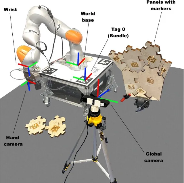
drawFrameAxes draws for you.Photo: Swilcock0 · CC BY 4.0 · Source: Wikimedia Commons · resized, converted to WebP
- Packing cells: the pose of each box decides the gripper angle; a 45° mistake means a crushed corner.
- Mobile robots: a marker on a charging dock gives the robot its pose relative to the dock for the final parking move.
- Calibration: the same PnP maths finds the camera’s pose from a checkerboard — you will use it in Lesson 16 to place the camera in the robot’s frame.
Think
Think about it
Think
A plain red cube (no marker) is lying on the table. Your detector gives you its four top corners perfectly. Can you know its yaw exactly? What about a rectangular 40 × 80 mm block?
Experiment
Try it in the lab
About 50 minutes. Python part: NumPy + OpenCV (4.7 or newer for ArucoDetector). Real part: your calibrated webcam and a printed marker. Bench: Arduino UNO, SG90, separate 5 V supply, 2 LEDs.
Experiment
Measure a pose and break it on purpose
You will need
- `pose_estimation_lab.py`, `marker_pose_live.py` (opencv-python, numpy; pyserial for the servo)
- Object pose estimator (browser)
- Printed ArUco marker (ID 3, DICT_4X4_50) on a block, ruler
- `camera_calib.npz` from Lesson 12
- Bench: UNO, SG90, 5–6 V supply, 470 µF capacitor, green + yellow LED, 2 × 220 Ω
Steps
- Run `pose_estimation_lab.py`. Change `L` to 30 mm (without changing the render) and predict the new distance before you run it.
- Change the corner noise in section 3 from 0.5 to 1.5 px. At which distance does the position spread pass 10 mm?
- In the pose estimator, sweep the yaw slider and lower the confidence below the gate. When does the arm stop getting a target?
- Real camera: put the marker at 30, 50 and 80 cm against a tape measure. Write down z from the script and the tape.
- Bench: send `Y 30`, `Y -40`, `Y 60` (should be refused), then stop sending and watch the wrist hold and the LED blink.
Interactive · Object pose estimator · Educational
Pose = position + orientation in the camera frame. Gate on confidence, transform to the arm base (TF / Stage 10), feed Stage 8 IK and Stage 9 trajectories. Teaching overlay only — not PnP/ArUco/OpenCV.
- Wrong size → wrong distance, same tiny error.
- Far, small markers → more jitter and more flipped tilts.
- Real z should be within a few mm at 30 cm; if not, re-check calibration and the printed size.
Knowledge check
Check your understanding
Knowledge check
1. How many numbers describe a full 6-DOF pose?
2. What does cv.solvePnP need besides the 2D image points?
3. You typed the marker side as 50 mm but it is really 40 mm. What happens?
4. Why does a single flat square marker sometimes give two different tilts?
5. A square block reports yaw −65°. Which gripper yaw needs the smallest wrist turn?
6. How do you get the object pose in the robot’s base frame?
Mini assignment
Hands-on assignment
Mini assignment
Pose of three blocks, checked with a ruler
Find the pose of three marked blocks with your webcam, check them against measurements, and drive the wrist servo.
Deliverables
- Screenshots with axes drawn on three blocks at different yaws.
- A table: measured vs estimated distance and yaw for each block, with errors.
- One example of a bad pose (too far, glare or wrong size) and how you detected it.
- A 20-second video of the wrist servo following a block you rotate by hand (and holding when you cover the marker).
Do this, step by step
- Print ArUco marker ID 3 (DICT_4X4_50) and measure its side length L in mm with a ruler.
- Run
marker_pose_live.pyon three blocks at different yaws and save screenshots with axes. - Fill a table: measured vs estimated distance and yaw, with errors.
- Make one bad pose on purpose (too far, glare or wrong size) and note how you detected it.
- Connect
wrist_yaw_servo.ino, rotate a block by hand, then cover the marker and check the servo holds.
Stuck? Hints, one at a time
- If every distance is off by the same ratio, the marker size L is wrong.
- A high reprojection error means bad corners — check glare and focus before trusting the pose.
- Yaw outside ±45° is refused with
ERR range -45..45, not clipped — that is what theY 60test checks.
Challenges (pick by level)
- 🟢 Beginner: Use
cv.projectPointsto draw a 40 mm wireframe cube on top of a marker (like the OpenCV pose tutorial). - 🟡 Intermediate: Average the pose over 5 frames and compare the jitter with single-frame poses.
- 🟠 Advanced: Put two markers on one tray and use both (8 corners) in one
solvePnPcall. Is the pose steadier? - 🔴 Expert: Use
cv.solvePnPRansacwith 6 points on a non-flat object (e.g. corners of an L-shaped part) and add one wrong point on purpose. Does RANSAC reject it? - ⚫ Research: Read how ArUco boards and ChArUco boards reduce pose ambiguity, and measure the tilt flip rate of a single marker vs a 2 × 2 board at 1 m.
Next step
You can now see a block, find its depth and its full pose. In Lesson 16 — the Stage 11 capstone you join everything: camera → pose → robot base frame → IK → trajectory → a real pick and place on the 6DOF arm, with safety gates at every step.
Sources
- OpenCV 4.x — Perspective-n-Point (PnP) pose computation — projection model, rvec/tvec meaning, camera axes (x right, y down, z forward), SOLVEPNP_IPPE_SQUARE corner order, P3P up to 4 solutions, solvePnPGeneric, solvePnPRansac.
- OpenCV 4.x — Detection of ArUco Markers — markers, dictionaries, corner order (clockwise from top-left),
ArucoDetector, pose withsolvePnPanddrawFrameAxes, marker length sets tvec units. - OpenCV 4.x — Pose Estimation (Python tutorial) — pose from a calibrated checkerboard, drawing axes and a cube with
projectPoints. - Wikipedia — Perspective-n-Point — 6-DOF pose definition, calibrated camera assumption, P3P up to four solutions, EPnP, RANSAC for outliers, uses in robotics and AR.
- Photos: Wikimedia Commons (credits under each image).
Look back: Lesson 14: Depth & 3D Vision. Next: Lesson 16: Capstone — Vision-Guided 6DOF Robot Pick & Place. Related: Stage 11 — Computer Vision, Stage 13 — Perception, Planning & Manipulation.
Self-attested for now — keep artifacts in your lab notebook.
Complete
Today's goal
0 of 1 done today
Mark this lesson complete when you have worked the experiment, knowledge check, and assignment (even roughly).