
Robot Perception, Planning & Manipulation · Lesson 03
Objects, Poses & Coordinate Frames
Est. 60–75 min
Why
Why this lesson matters
In Lesson 2 each object in the world model had a pose. Now you will learn what a pose really is — a position and an orientation of one frame, written in another frame — and how to move a pose from the camera to the base to the gripper without mistakes. This is the everyday maths of manipulation.
You will chain 4 × 4 transforms in plain Python, compute a grasp and pre-grasp, compare four ways of writing orientation, and break things on purpose: wrong order, wrong inverse, degrees vs radians, and offsets in the wrong frame. On the bench, an Arduino turns an ultrasonic reading on a pan servo into a point in the base frame.
Concept
Position + orientation, always in a named frame
1. Frames: a ruler and a compass glued to something
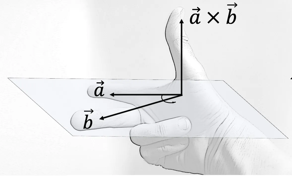
A coordinate frame is an origin point plus three perpendicular axes x, y, z. We glue frames to things: base_link to the arm base, camera_optical to the camera lens, tool0 or gripper to the hand, and one frame to each object. ROS’s REP 103 sets common rules: SI units (metres, radians), right-handed frames, and for a body x forward, y left, z up. Camera “optical” frames are different: z forward, x right, y down.
2. A pose is a transform
The pose of frame B in frame A is written T_A_B (read: “B as seen from A”). It is a 4 × 4 matrix: a 3 × 3 rotation R and a position p, with a last row of 0 0 0 1. Multiplying it by a point written in B gives the same point written in A: p_A = T_A_B · p_B.
        | r11 r12 r13  px |
T_A_B = | r21 r22 r23  py |     columns of R = B's x, y, z axes written in A
        | r31 r32 r33  pz |     p            = B's origin written in A
| 0 0 0 1 |- Chain:
T_base_block = T_base_cam · T_cam_block. The inner names must match (cam … cam), like dominoes. - Invert:
T_cam_base = inverse(T_base_cam). For a transform, the inverse is[Rᵀ, −Rᵀp]— no general matrix inverse needed. - Order matters:
A · Bis notB · Afor rotations. The script shows a 13 cm error from swapping them. - Offsets in the tool frame: “back off 8 cm along the gripper” is
T_base_grasp · Trans(0, 0, −0.08)— multiply on the right. Multiply on the left and you move along the base axes instead.
3. Four ways to write orientation
| Format | Numbers | Good | Watch out |
|---|---|---|---|
| Rotation matrix | 9 (3 × 3) | Easy to chain; no singularities | Must stay orthonormal with det +1 |
| Quaternion (w, x, y, z) | 4, length 1 | Compact; no singularities; ROS messages use it | q and −q are the same rotation; normalise after maths |
| Axis–angle | 3 + 1 | Easy to picture: “turn 30° about z” | Angle 0 has no defined axis |
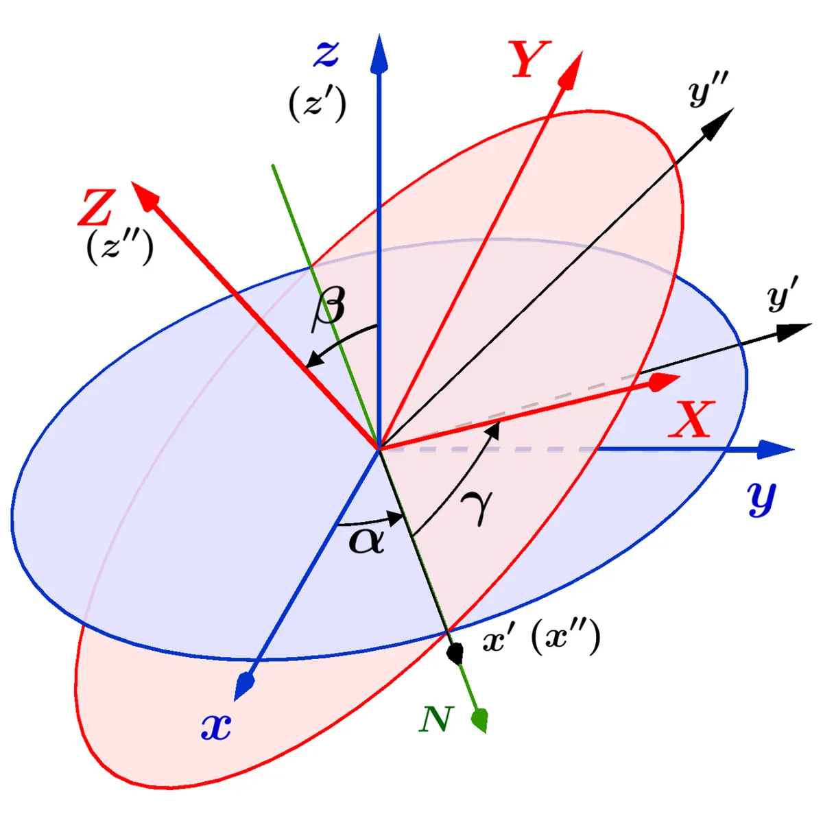
| Roll–pitch–yaw / Euler | 3 | Easy for humans to read | Many conventions; gimbal lock at pitch ±90° |
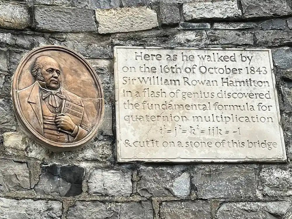
A rotation of θ about a unit axis (x, y, z) is the quaternion (cos θ/2, x·sin θ/2, y·sin θ/2, z·sin θ/2). So “−30° about z” is (0.9659, 0, 0, −0.2588). The script checks this.
4. Gimbal lock — why robots avoid Euler angles inside
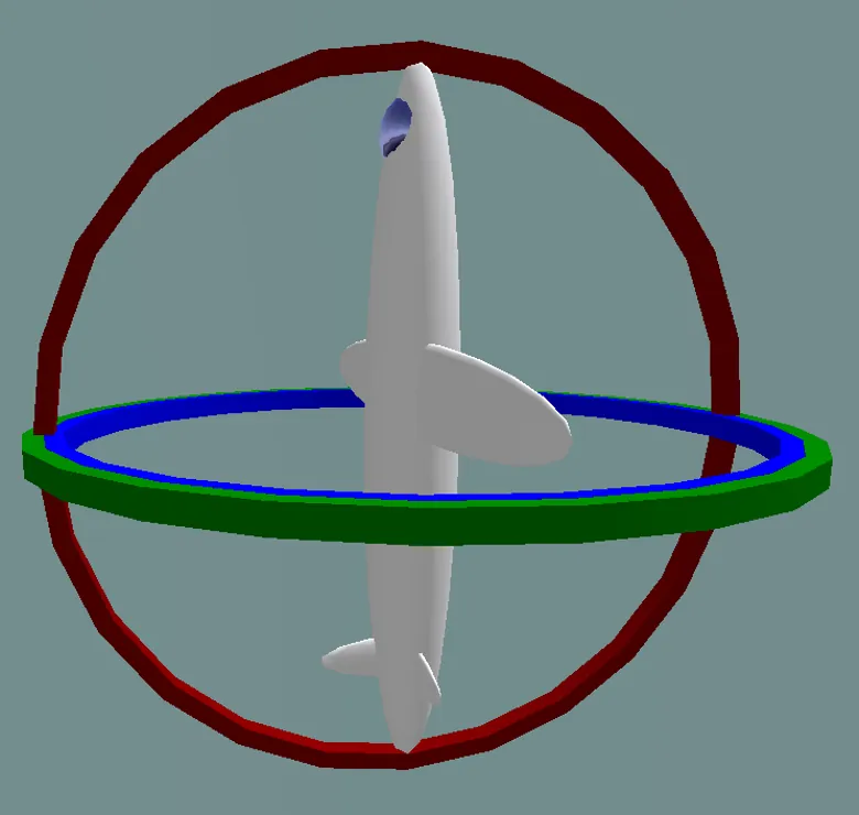
With three angles applied one after another, there are special positions where two rotation axes line up. Then one degree of freedom is lost: changing roll or yaw does the same thing. This is gimbal lock. It happened to the Apollo 11 guidance platform, whose computer warned near the locked position and froze the platform at 85° — Michael Collins joked about wanting “a fourth gimbal for Christmas”. In robot arms the same thing is called wrist flip, when two wrist axes line up. Inside software, store orientation as a quaternion or a matrix, and use roll–pitch–yaw only for showing numbers to people.
5. Poses you need for one pick
| Pose | Written in | Comes from |
|---|---|---|
| T_base_cam | base_link | camera mount + calibration (fixed) |
| T_cam_block | camera_optical | detector, every frame |
| T_base_block | base_link | chain of the two above — goes into the world model |
| T_block_grasp | block | grasp choice: where the gripper sits relative to the object |
| T_base_grasp | base_link | T_base_block · T_block_grasp — the IK target |
| T_base_pregrasp | base_link | T_base_grasp · Trans(0, 0, −d) — back off along the approach axis |
Visual
Visualise it: one object, many frames
The same block has a different pose in every frame — camera, base and gripper. Move things around and watch the numbers change while the block itself stays put. (Educational explorer, not a calibration tool.)
Interactive · Object pose & frame lab · Educational

Educational frame change stub — not industrial 6D pose / not live TF2 tree.
Code lab
Code lab: chain, grasp, break, convert
pose_frames_lab.py uses plain Python lists for 4 × 4 matrices (no numpy). The overhead camera is 60 cm above the base plane at x = 15 cm, looking straight down (example values). The detector reports a 4 cm block 57 cm in front of the lens, turned +30° about the camera z axis. The script moves this into base_link, builds the grasp and pre-grasp poses, checks the round trip, makes five classic mistakes, prints the orientation four ways and shows gimbal lock. Run python3 pose_frames_lab.py.
"""pose_frames_lab.py — Stage 13 L03 (AIHUB STATION lab)

Poses and coordinate frames for a desk arm, with plain Python (no numpy).
A pose = position + orientation of one frame, written in another frame.
We store it as a 4x4 homogeneous transform  T_parent_child.

Frames (example values, metres):
  base_link          : arm base. x forward, y left, z up (ROS REP 103 body frame)
  camera_optical     : overhead camera 60 cm above the base plane, at x = 0.15.
                       Optical convention: z forward (down at the desk), x right, y down.
  block              : detected block, 4 cm cube
  grasp / pregrasp   : where the gripper frame must go (gripper z = approach axis)
Run:  python3 pose_frames_lab.py
"""
import math

def matmul(A, B):
    return [[sum(A[i][k]*B[k][j] for k in range(4)) for j in range(4)] for i in range(4)]
def T(R=None, p=(0, 0, 0)):
    R = R or [[1, 0, 0], [0, 1, 0], [0, 0, 1]]
    return [R[0] + [p[0]], R[1] + [p[1]], R[2] + [p[2]], [0, 0, 0, 1]]
def Rz(a):
    c, s = math.cos(a), math.sin(a); return [[c, -s, 0], [s, c, 0], [0, 0, 1]]
def Ry(a):
    c, s = math.cos(a), math.sin(a); return [[c, 0, s], [0, 1, 0], [-s, 0, c]]
def Rx(a):
    c, s = math.cos(a), math.sin(a); return [[1, 0, 0], [0, c, -s], [0, s, c]]
def rot(Tm): return [row[:3] for row in Tm[:3]]
def pos(Tm): return [Tm[i][3] for i in range(3)]
def inv(Tm):
    R = rot(Tm); p = pos(Tm)
    Rt = [[R[j][i] for j in range(3)] for i in range(3)]
    return T(Rt, [-sum(Rt[i][k]*p[k] for k in range(3)) for i in range(3)])
def det3(R):
    return (R[0][0]*(R[1][1]*R[2][2]-R[1][2]*R[2][1]) - R[0][1]*(R[1][0]*R[2][2]-R[1][2]*R[2][0])
            + R[0][2]*(R[1][0]*R[2][1]-R[1][1]*R[2][0]))
def yaw_of(Tm): return math.degrees(math.atan2(Tm[1][0], Tm[0][0]))
def cm(p): return "(" + ", ".join(f"{v*100:6.1f}" for v in p) + ") cm"
def quat(R):
    """rotation matrix -> unit quaternion (w, x, y, z)"""
    w = math.sqrt(max(0, 1 + R[0][0] + R[1][1] + R[2][2])) / 2
    x = math.copysign(math.sqrt(max(0, 1 + R[0][0] - R[1][1] - R[2][2])) / 2, R[2][1] - R[1][2])
    y = math.copysign(math.sqrt(max(0, 1 - R[0][0] + R[1][1] - R[2][2])) / 2, R[0][2] - R[2][0])
    z = math.copysign(math.sqrt(max(0, 1 - R[0][0] - R[1][1] + R[2][2])) / 2, R[1][0] - R[0][1])
    return (w, x, y, z)
def apply(Tm, p):
    return [sum(Tm[i][k]*p[k] for k in range(3)) + Tm[i][3] for i in range(3)]

# ---- 1. the camera mount: T_base_cam ----
# optical x (right in image) = base +x, optical y (down in image) = base -y, optical z = base -z
R_base_cam = [[1, 0, 0], [0, -1, 0], [0, 0, -1]]
T_base_cam = T(R_base_cam, (0.15, 0.0, 0.60))
print("1. Camera mount  T_base_cam")
print(f"   det(R) = {det3(R_base_cam):+.0f}  (must be +1: a right-handed frame, not a mirror)")
print("   camera z axis in base =", [R_base_cam[i][2] for i in range(3)], "-> looking straight down")

# ---- 2. detector output: block pose in the camera frame ----
# detector: block centre 57 cm in front of the lens, turned +30 deg about the camera z axis.
# The block's own z axis points UP out of its top face, i.e. towards the camera (= camera -z),
# so we add a half turn about x:  R_cam_block = Rz(30) * Rx(180)
R_cb = [[sum(Rz(math.radians(30))[i][k]*Rx(math.pi)[k][j] for k in range(3)) for j in range(3)] for i in range(3)]
T_cam_block = T(R_cb, (0.05, 0.02, 0.57))
T_base_block = matmul(T_base_cam, T_cam_block)
print("\n2. Block from detector (camera frame): pos", cm(pos(T_cam_block)), " yaw +30.0 deg about camera z")
print("   Block in base_link: T_base_block = T_base_cam * T_cam_block")
print("   pos", cm(pos(T_base_block)), f" yaw {yaw_of(T_base_block):+.1f} deg about base z")
print("   (camera z points down, so +30 deg about camera z is -30 deg about base z)")

# ---- 3. grasp and pre-grasp ----
# gripper frame: z = approach (points down into the block), fingers close along gripper y
T_block_grasp = T(Rx(math.pi), (0, 0, 0.0))           # flip: gripper z = -block z (down), at the block centre
T_base_grasp = matmul(T_base_block, T_block_grasp)
T_base_pre = matmul(T_base_grasp, T(p=(0, 0, -0.08)))   # 8 cm back along the gripper's own approach axis
print("\n3. Grasp pose in base:    ", cm(pos(T_base_grasp)), "gripper z =", [round(rot(T_base_grasp)[i][2], 3) + 0 for i in range(3)])
print("   Pre-grasp (8 cm back): ", cm(pos(T_base_pre)), "-> straight above the block")
corner = apply(T_base_block, (0.02, 0.02, 0.02))
print("   One top corner of the 4 cm block in base:", cm(corner))

# ---- 4. check: round trip ----
I = matmul(inv(T_base_block), T_base_block)
err = max(abs(I[i][j] - (1 if i == j else 0)) for i in range(4) for j in range(4))
print(f"\n4. inv(T_base_block) * T_base_block = identity? max error {err:.1e}")
back = apply(inv(T_base_cam), pos(T_base_block))
print("   base -> camera again:", cm(back), "(matches the detector)")

# ---- 5. classic mistakes ----
truth = pos(T_base_block)
def err_mm(p): return math.dist(p, truth) * 1000
print("\n5. Classic mistakes (error of the block position in base_link)")
m1 = pos(matmul(T_cam_block, T_base_cam))
print(f"   a) wrong order T_cam_block*T_base_cam    : {cm(m1)}  error {err_mm(m1):6.1f} mm")
m2 = pos(matmul(inv(T_base_cam), T_cam_block))
print(f"   b) used T_cam_base instead of T_base_cam: {cm(m2)}  error {err_mm(m2):6.1f} mm")
m3 = pos(matmul(T(None, (0.15, 0.0, 0.60)), T_cam_block))
print(f"   c) forgot the camera rotation           : {cm(m3)}  error {err_mm(m3):6.1f} mm")
yaw_bad = math.degrees(math.atan2(math.sin(30), math.cos(30)))
print(f"   d) degrees given to sin/cos as radians  : yaw 30 -> {yaw_bad:+.1f} deg (wanted +30.0)")
# e) pre-grasp offset in the wrong frame, for a gripper tilted 45 deg about base y
T_tilt = matmul(T_base_grasp, T(Ry(math.radians(45))))
good = pos(matmul(T_tilt, T(p=(0, 0, -0.08))))
bad = [pos(T_tilt)[0], pos(T_tilt)[1], pos(T_tilt)[2] + 0.08]
print(f"   e) tilted 45 deg gripper, pre-grasp 8 cm 'up in base' instead of 'back along tool z':")
print(f"      tool-frame pre-grasp {cm(good)}  vs base-frame {cm(bad)}  -> {math.dist(good, bad)*1000:.1f} mm apart")

# ---- 6. orientation formats ----
print("\n6. Orientation of the block in base_link, four ways")
Rb = rot(T_base_block)
print("   rotation matrix rows:", [[round(v, 3) + 0 for v in r] for r in Rb])
q = quat(Rb)
print("   quaternion (w,x,y,z):", tuple(round(v, 4) + 0 for v in q),
      f"  expected (cos(-15), 0, 0, sin(-15)) = ({math.cos(math.radians(-15)):.4f}, 0, 0, {math.sin(math.radians(-15)):.4f})")
print("   -q is the SAME rotation:", tuple(round(-v, 4) + 0 for v in q))
print(f"   axis-angle: about +z by {yaw_of(T_base_block):+.1f} deg;  yaw (RPY) = {yaw_of(T_base_block):+.1f} deg")
qd = (q[0]*1.003, q[1]*1.003, q[2], q[3]*1.003)
n = math.sqrt(sum(v*v for v in qd))
print(f"   after drift |q| = {n:.4f} -> normalise to 1 before use")

# ---- 7. gimbal lock ----
print("\n7. Gimbal lock: R = Rz(yaw) * Ry(pitch) * Rx(roll) with pitch = 90 deg")
def rpy(roll, pitch, yaw):
    A = [[sum(Rz(yaw)[i][k]*Ry(pitch)[k][j] for k in range(3)) for j in range(3)] for i in range(3)]
    return [[sum(A[i][k]*Rx(roll)[k][j] for k in range(3)) for j in range(3)] for i in range(3)]
for r, y in ((10, 0), (0, -10), (40, 30)):
    R = rpy(math.radians(r), math.radians(90), math.radians(y))
    print(f"   roll {r:+3d}, yaw {y:+3d} -> first row {[round(v, 3) + 0 for v in R[0]]}, quat {tuple(round(v, 3) + 0 for v in quat(R))}")
print("   All three give the SAME rotation: at pitch 90 deg only (roll - yaw) matters. One degree of freedom is lost.")
Output (run with python3 pose_frames_lab.py)
1. Camera mount  T_base_cam
   det(R) = +1  (must be +1: a right-handed frame, not a mirror)
   camera z axis in base = [0, 0, -1] -> looking straight down

2. Block from detector (camera frame): pos (   5.0,    2.0,   57.0) cm  yaw +30.0 deg about camera z
   Block in base_link: T_base_block = T_base_cam * T_cam_block
   pos (  20.0,   -2.0,    3.0) cm  yaw -30.0 deg about base z
   (camera z points down, so +30 deg about camera z is -30 deg about base z)

3. Grasp pose in base:     (  20.0,   -2.0,    3.0) cm gripper z = [0.0, 0.0, -1.0]
   Pre-grasp (8 cm back):  (  20.0,   -2.0,   11.0) cm -> straight above the block
   One top corner of the 4 cm block in base: (  22.7,   -1.3,    5.0) cm

4. inv(T_base_block) * T_base_block = identity? max error 1.0e-17
   base -> camera again: (   5.0,    2.0,   57.0) cm (matches the detector)

5. Classic mistakes (error of the block position in base_link)
   a) wrong order T_cam_block*T_base_cam    : (  18.0,    9.5,   -3.0) cm  error  131.3 mm
   b) used T_cam_base instead of T_base_cam: ( -10.0,   -2.0,    3.0) cm  error  300.0 mm
   c) forgot the camera rotation           : (  20.0,    2.0,  117.0) cm  error 1140.7 mm
   d) degrees given to sin/cos as radians  : yaw 30 -> -81.1 deg (wanted +30.0)
   e) tilted 45 deg gripper, pre-grasp 8 cm 'up in base' instead of 'back along tool z':
      tool-frame pre-grasp (  15.1,    0.8,    8.7) cm  vs base-frame (  20.0,   -2.0,   11.0) cm  -> 61.2 mm apart

6. Orientation of the block in base_link, four ways
   rotation matrix rows: [[0.866, 0.5, 0.0], [-0.5, 0.866, 0.0], [0.0, 0.0, 1.0]]
   quaternion (w,x,y,z): (0.9659, 0.0, 0.0, -0.2588)   expected (cos(-15), 0, 0, sin(-15)) = (0.9659, 0, 0, -0.2588)
   -q is the SAME rotation: (-0.9659, 0.0, 0.0, 0.2588)
   axis-angle: about +z by -30.0 deg;  yaw (RPY) = -30.0 deg
   after drift |q| = 1.0030 -> normalise to 1 before use

7. Gimbal lock: R = Rz(yaw) * Ry(pitch) * Rx(roll) with pitch = 90 deg
   roll +10, yaw  +0 -> first row [0.0, 0.174, 0.985], quat (0.704, 0.062, 0.704, -0.062)
   roll  +0, yaw -10 -> first row [0.0, 0.174, 0.985], quat (0.704, 0.062, 0.704, -0.062)
   roll +40, yaw +30 -> first row [0.0, 0.174, 0.985], quat (0.704, 0.062, 0.704, -0.062)
All three give the SAME rotation: at pitch 90 deg only (roll - yaw) matters. One degree of freedom is lost.Try it: move and rotate the object and the camera, and watch its pose change in each frame. (Educational explorer, not a calibration tool.)
Interactive · Object pose & frame lab · Educational
Educational frame change stub — not industrial 6D pose / not live TF2 tree.
Bench build: sensor reading → base frame on the UNO
sensor_to_base.ino mounts an HC-SR04 on a small pan servo. A potentiometer sets the pan angle from −60° to +60°. The sensor measures distance d along its own x axis, so the object is at (d, 0, 0) in the sensor frame. The sketch chains T_base_sensor = Trans(5, 0, 10 cm) · Rz(yaw) (example mount) and prints the object position in base_link. Notice the line yaw = yawDeg * PI / 180.0 — the sin/cos functions need radians.
| Part | Connection | Note |
|---|---|---|
| Potentiometer 10 kΩ | ends → 5V and GND, wiper → A0 | sets the pan angle |
| HC-SR04 | VCC → 5V, GND → GND, TRIG → D7, ECHO → D8 | mounted on the servo horn, pointing along the horn |
| Pan servo (SG90-class) | signal → D9 | power from a separate 5–6 V supply |
| Servo supply | red → +5–6 V, brown → supply GND | supply GND joined to UNO GND |
// sensor_to_base.ino — Stage 13 L03 (AIHUB STATION lab)
// Turn a sensor reading into a point in the robot's BASE frame.
// A potentiometer sets a pan servo angle; an HC-SR04 sits on the servo horn and
// measures distance d along its own x axis. We chain two transforms:
//   T_base_sensor = Trans(MOUNT_X, 0, MOUNT_Z) * Rz(yaw)
//   p_base        = T_base_sensor * (d, 0, 0)
// and print the object position in base_link (x forward, y left, z up), in cm.
//
// Wiring (example): pot ends to 5V/GND, wiper to A0. HC-SR04 TRIG D7, ECHO D8.
//   Servo signal D9; servo power from a SEPARATE 5-6 V supply (never GPIO or the
//   UNO 5V pin), grounds joined.
#include <Servo.h>

const int TRIG = 7, ECHO = 8, SERVO_PIN = 9, POT = A0;
const float MOUNT_X = 5.0, MOUNT_Z = 10.0;     // servo axis: 5 cm in front of base, 10 cm up (example)
const int YAW_MIN = -60, YAW_MAX = 60;          // degrees about base z (left = +)
Servo pan;

float readCm() {
  digitalWrite(TRIG, LOW);  delayMicroseconds(2);
  digitalWrite(TRIG, HIGH); delayMicroseconds(10);
  digitalWrite(TRIG, LOW);
  unsigned long us = pulseIn(ECHO, HIGH, 30000UL);
  return us == 0 ? -1 : us / 58.0;
}

void setup() {
  Serial.begin(115200);
  pinMode(TRIG, OUTPUT); pinMode(ECHO, INPUT);
  pan.attach(SERVO_PIN);
  Serial.println(F("yaw_deg  d_sensor_cm  ->  base x  y  z (cm)"));
}

void loop() {
  int yawDeg = map(analogRead(POT), 0, 1023, YAW_MIN, YAW_MAX);
  pan.write(90 + yawDeg);                 // servo 90 = straight ahead (calibrate yours)
  delay(150);
  float d = readCm();
  if (d < 2 || d > 200) {                 // trust 2..200 cm only
    Serial.print(yawDeg); Serial.println(F("   no trusted echo"));
    return;
  }
  float yaw = yawDeg * PI / 180.0;        // sin/cos need RADIANS
  // p_sensor = (d, 0, 0)  ->  rotate by Rz(yaw), then translate by the mount offset
  float x = MOUNT_X + cos(yaw) * d;
  float y = 0.0     + sin(yaw) * d;
  float z = MOUNT_Z;
  Serial.print(yawDeg); Serial.print(F("      ")); Serial.print(d, 1);
  Serial.print(F("        ->  ")); Serial.print(x, 1); Serial.print(F("  "));
  Serial.print(y, 1); Serial.print(F("  ")); Serial.println(z, 1);
}yaw_deg d_sensor_cm -> base x y z (cm)
0 20.0 -> 25.0 0.0 10.0
30 20.0 -> 22.3 10.0 10.0
-45 15.0 -> 15.6 -10.6 10.0
60 no trusted echoDebugging
| Symptom | Likely cause | Fix |
|---|---|---|
| Object appears mirrored (left/right swapped) | a left-handed frame or a wrong axis sign | Check det(R) = +1; test with one known point |
| Error grows with distance from the camera | rotation part of T_base_cam slightly wrong | Re-calibrate; check with points at the image edges |
| Position is right, gripper is turned wrong | orientation chained in the wrong order, or yaw sign flipped by the camera frame | Write T_A_B names; check inner names match |
| Approach comes from the side, not from above | pre-grasp offset applied in the base frame | Multiply the offset on the right (tool frame) |
| Angles jump by huge amounts | degrees passed to sin/cos | Convert to radians; keep radians inside the code |
| Orientation slowly drifts after many updates | quaternion not normalised | Normalise after every multiplication |
| Bench: base x, y change when you only turn the pot | mount offset or servo zero wrong | Measure MOUNT_X; set the servo so 90 = straight ahead |
Real world
Frames in the real world
- ROS robots: tf2 keeps all frames of a robot in a tree, buffered in time, so any node can ask “where was the block in
base_linkat time t?” without knowing the chain in between. - Industrial arms: you program the tool centre point (TCP) as a frame on the gripper, and teach work-object frames on fixtures, so a program still works when the fixture is moved.
- Phones and drones: inertial sensors integrate rotation with quaternions instead of gimbals — the strapdown approach that avoids gimbal lock.
- Your lab: write down
base_link,camera_optical,gripperandblockfor your desk arm, with real measured offsets, before you write any picking code.
Think
Think about it
Think
Your camera is on the robot’s wrist instead of above the desk. Which transforms in the pick chain now change every time the arm moves, and what extra information do you need at the exact moment the image was taken?
Experiment
Try it in the lab
About 60 minutes. Python 3 for the script; Arduino UNO, HC-SR04, a small servo with its own 5–6 V supply and a 10 kΩ potentiometer for the bench; a ruler.
Experiment
Move one block through every frame
You will need
- `pose_frames_lab.py` (Python 3, no libraries)
- Object-pose frame lab (in your browser)
- Arduino UNO, HC-SR04, SG90-class servo + separate 5–6 V supply, 10 kΩ potentiometer, jumper wires, a box, a ruler
Steps
- Run `pose_frames_lab.py`. Check the block position in base by hand: x = 15 + 5, y = 0 − 2, z = 60 − 57.
- Change the detector yaw from +30° to +90°. What is the yaw in base? Explain the sign.
- Change the pre-grasp distance to 5 cm and 12 cm. Where does each pre-grasp land?
- In mistake 5e, try tilts of 15°, 30° and 60°. Plot how far apart the two pre-grasps are.
- Write a function that turns a quaternion back into a rotation matrix and check it on the block orientation.
- Bench: put a box at a measured spot (for example 25 cm ahead). Read base x, y at yaw −30°, 0°, +30° of the pot. How much do they vary?
- Bench: deliberately set MOUNT_X wrong by 3 cm. Which printed number changes, and by how much?
Interactive · Object pose & frame lab · Educational
Educational frame change stub — not industrial 6D pose / not live TF2 tree.
A transform is just a careful way of saying “this point, seen from there”. When the frame names are written down and the inner names match, the maths almost writes itself.
Knowledge check
Check your understanding
Knowledge check
1. A pose is…
2. In REP 103, a body frame uses…
3. Which chain gives the block in the base frame?
4. A rotation matrix has determinant −1. This means…
5. The quaternion for −30° about z is about…
6. To back off 8 cm along the gripper’s own approach axis you compute…
7. Gimbal lock means…
8. In the bench sketch, why multiply yawDeg by PI / 180?
Mini assignment
Hands-on assignment
Mini assignment
A frame map for your desk arm
Draw, measure and test every frame your desk arm needs for one pick.
Deliverables
- A labelled drawing of `base_link`, `camera_optical`, `gripper` and `block` frames with axis directions, following REP 103.
- Your measured T_base_cam (position in cm and orientation as a quaternion), clearly marked as measured or estimated.
- A table of three real points: ruler position vs the position your code computes, with the error in mm.
- A bench log from `sensor_to_base.ino` for one fixed box seen at three different pan angles.
Do this, step by step
- Run
pose_frames_lab.pyand read the error lines for each mistake it shows. - Draw
base_link,camera_optical,gripperandblockwith axes as in REP 103 (x forward, y left, z up). - Measure your T_base_cam with a ruler and write it as position (cm) plus quaternion.
- Check three ruler points against your computed points and write the error in mm.
- Bench: set
MOUNT_XandMOUNT_Zto your servo mount, uploadsensor_to_base.inoand log one fixed box at three pan angles.
Stuck? Hints, one at a time
- If the error looks like the point was mirrored, you probably multiplied in the wrong order. Moving along the gripper’s own axis means multiplying on the right.
- Check
det3(R)is 1. If it is −1, one of your axes is flipped (left-handed frame). - In the sketch,
sin()andcos()want radians, so multiplyyawDegby PI / 180 before using it.
Challenges (pick by level)
- 🟢 Beginner: By hand, move the point (2, 0, 0) cm through Rz(90°) and then Trans(10, 0, 0) cm. Then do it in the other order. Explain the difference.
- 🟡 Intermediate: Add a
camera_link→camera_opticalstep to the script (body frame to optical frame) and check you get the same block pose. - 🟠 Advanced: Add a tilt servo to the bench build, chain
Rz(yaw) · Ry(pitch), and print full 3D positions. - 🔴 Expert: With an OpenCV ArUco marker, measure
T_cam_markerfrom a real webcam and compute the marker in your arm’s base frame. - ⚫ Research: Read about hand–eye calibration (AX = XB). Write one page on how you would calibrate a wrist camera on your desk arm.
Next step
Now every object has a proper pose. But the planner also needs to know the space objects take up. In Lesson 4 — Occupancy & Collision Representation you will turn objects into boxes, spheres and voxels that a planner can check collisions against.
Look back: Lesson 2: Robot World Models. Next: Lesson 4: Occupancy & Collision Representation. Related: Stage 8 — Kinematics & IK.
Sources
- ROS REP 103 — Standard Units of Measure and Coordinate Conventions (source text, GitHub) — SI units, right-handed frames, x forward / y left / z up, optical frames z forward / x right / y down, rotation representation preference.
- tf2 README (ros2/geometry2, GitHub) — frames kept in a tree buffered in time; transform data between any two frames at any time.
- Wikipedia — Quaternions and spatial rotation — rotation of θ about a unit axis as (cos θ/2, axis · sin θ/2).
- Wikipedia — Gimbal lock — loss of a degree of freedom, Apollo 11 IMU, wrist flip in robots, quaternion and matrix alternatives.
- HC-SR04 datasheet (SparkFun-hosted PDF) — 2 cm–4 m range, 10 µs trigger, 15° measuring angle.
- Arduino Servo library (GitHub) — controlling RC hobby servos.
- Photos: Wikimedia Commons (credits under each image).
Self-attested for now — keep artifacts in your lab notebook.
Complete
Today's goal
0 of 1 done today
Mark this lesson complete when you have worked the experiment, knowledge check, and assignment (even roughly).