
Computer Vision for Robotics (Vision Foundations) · Lesson 02
How Cameras See the World
Est. 50–65 min
Why
Why this lesson matters
Think of standing on a railway platform. The train coach right in front of you looks huge; the same-size coach at the far end of the platform looks tiny. Your eye did not measure the coaches wrongly — far things simply cover a smaller part of your view. A camera works the same way, and it does it with a very simple formula. In Lesson 1 we saw that a robot gets only numbers from a camera. In this lesson you learn where those numbers come from: light, a lens, a sensor of tiny pixels, and the pinhole model that maps a 3D point to a pixel (u, v).
Why should a robotics student care? Because every later step in Stage 11 depends on it. Converting a block’s pixel position into centimetres for IK (Stage 8), knowing how far one pixel is on the table, choosing a camera height and resolution, understanding why one camera cannot tell depth — all of it is the pinhole model. You will compute it by hand, check it against OpenCV, measure your own webcam, and build a one-pixel “camera” on an Arduino to feel what exposure time means.
Concept
From light to pixels: the pinhole camera
1. The camera obscura: a dark room with a small hole
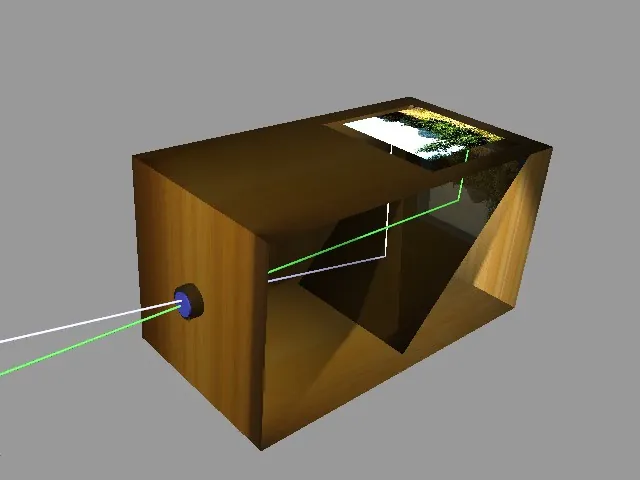
Long before electronics, people noticed that light coming through a small hole into a dark room makes an image of the outside scene on the opposite wall — upside down and left-right reversed. This is the *camera obscura* (Latin for “dark chamber”). Every straight ray from a point outside passes through the hole and hits exactly one spot on the wall. A modern camera is the same idea: the hole became a lens (which gathers more light), and the wall became an electronic sensor.
2. The pinhole model: one formula for every pixel
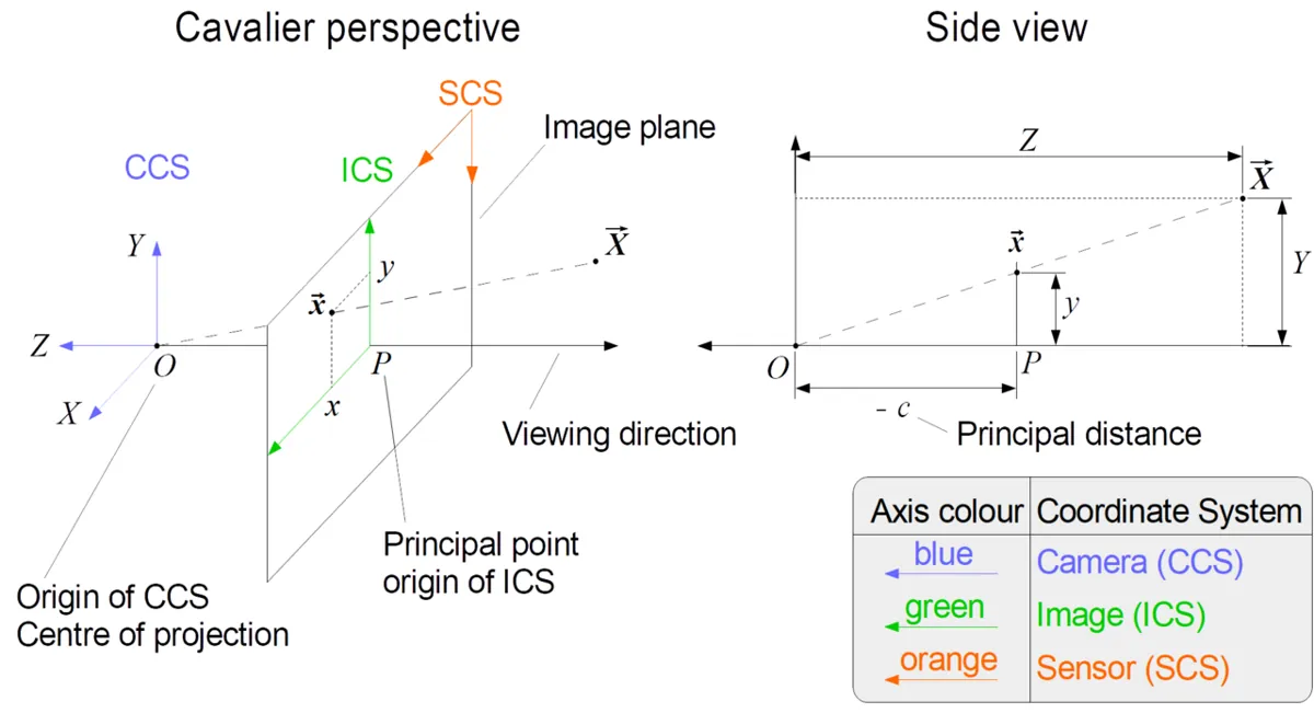
We put the camera at the origin. Z points straight out of the lens, X to the right and Y downwards (this is the camera frame OpenCV uses). For a point (X, Y, Z) in front of the camera, the pixel where it appears is:
u = fx · X / Z + cx
v = fy · Y / Z + cy

fx, fy = focal length in PIXELS
cx, cy = principal point (where the lens axis hits the image, near the centre)| Symbol | Meaning | Everyday picture |
|---|---|---|
| X, Y, Z | position of the point in the camera frame (for example cm) | Z is “how far in front of the lens” |
| X / Z, Y / Z | the direction of the ray | the angle at which you see the point |
| fx, fy | focal length measured in pixels | zoom: bigger fx → objects look bigger |
| cx, cy | principal point in pixels | the image centre the lens really uses |
| u, v | pixel column and row (top-left is 0, 0) | where the point lands on the photo |
3. Focal length in pixels, field of view and resolution
Lens boxes print focal length in millimetres, but vision code needs it in pixels. The OpenCV docs give both links: fx = focal_length_mm / pixel_size_mm, and from the field of view, f = sensor_width / (2 · tan(FOV / 2)). Working directly in pixels, the horizontal field of view of an image W pixels wide is FOV = 2 · atan(W / (2 · fx)). A 640-px-wide image with fx = 600 px sees about 56°; a wide-angle camera with fx = 320 px sees 90°.
If you change the resolution of the same camera — say from 640 × 480 to 1280 × 960 — fx, fy, cx and cy all scale by the same factor (×2 here). The ray for each object does not change; you just have more pixels across it. The OpenCV docs also note that lens distortion coefficients stay the same when resolution changes. So: always use intrinsics that match the resolution you are actually capturing.
4. Inside the camera: lens, sensor and colour filters
Lens
Bends light so many rays from one point meet again on the sensor — a bright, sharp image instead of the dim one a tiny pinhole gives. Real lenses also bend straight lines a little near the edges (barrel or pincushion distortion); Lesson 12 measures and removes that.
Aperture and exposure
Each pixel collects light for a short exposure time. Longer exposure = brighter, less noisy picture, but a moving hand smears into motion blur. Shorter = sharp but dark and grainy.
Sensor
A grid of light-sensitive photosites (CMOS in almost every webcam and phone). Each one turns the light it collected into a number.
Colour filter (Bayer)
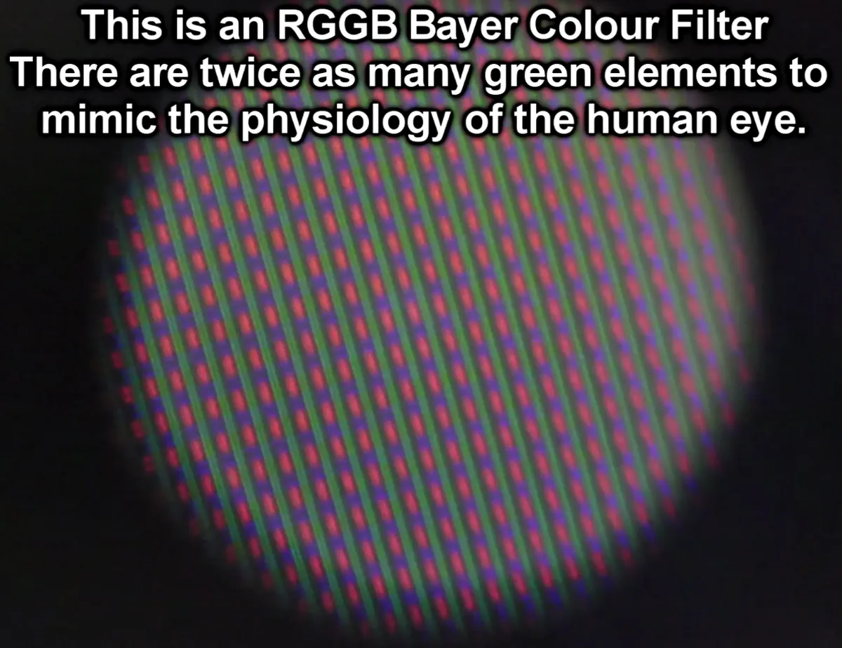
A photosite cannot tell colour, so a mosaic of tiny filters sits on top: half green, a quarter red, a quarter blue (the Bayer pattern, invented by Bryce Bayer at Kodak). The camera fills in the two missing colours at each pixel from its neighbours (demosaicing).
Readout
Most cheap sensors read rows one after another — a rolling shutter — so a fast-moving object can look slanted or bent. A global shutter captures all pixels at the same instant; it is preferred for fast robots and conveyors.
Visual
Visualise it: move the block, change the focal length
Educational projection lab: focal length fx, principal point and distance Z decide where points land in the image. (Browser sim, not OpenCV, not a real lens.)
Interactive · Camera calibration lab · Educational

Intrinsics K map rays to pixels; bad fx / unmodeled distortion raise reprojection residual. Projection collapses Z — robots recover depth later. Estimates are educational, not a real OpenCV calibration runtime.
Code lab
Code lab: project points like a camera
pinhole_projection.py uses only NumPy. It takes a typical 640 × 480 webcam with fx = fy = 600 px and (cx, cy) = (320, 240) — example numbers, not a calibrated camera — and runs six small experiments. At the end, if OpenCV is installed, it checks the hand formula against cv.projectPoints (with zero rotation, zero translation and no distortion). Run python3 pinhole_projection.py.
"""
pinhole_projection.py — Stage 11 Lesson 2: how a camera turns 3D points into pixels.

Uses the distortion-free pinhole model from the OpenCV calib3d docs:
    u = fx * X / Z + cx
    v = fy * Y / Z + cy
(X, Y, Z) are in the CAMERA frame: X right, Y down, Z forward out of the lens.

Needs only NumPy. If OpenCV is installed, the result is cross-checked with cv.projectPoints.
Run:  python3 pinhole_projection.py
"""
import math
import numpy as np

# A typical 640 x 480 USB webcam (example numbers, not a calibrated camera).
W, H = 640, 480
FX = FY = 600.0          # focal length in PIXELS
CX, CY = W / 2, H / 2    # principal point, near the image centre


def project(X, Y, Z, fx=FX, fy=FY, cx=CX, cy=CY):
    """3D point in camera frame (cm) -> pixel (u, v). Refuses points behind the lens."""
    if Z <= 0:
        raise ValueError(f"Z={Z}: point is behind (or on) the camera - not visible")
    return fx * X / Z + cx, fy * Y / Z + cy


def show(title):
    print("\n" + title)
    print("-" * len(title))


# 1. A 5 cm red block seen straight down from 50 cm.
show("1. A 5 cm block, camera 50 cm above the table")
left = project(-2.5, 0, 50)
right = project(2.5, 0, 50)
print(f"left edge  -> u={left[0]:6.1f} px")
print(f"right edge -> u={right[0]:6.1f} px")
print(f"block width in image = {right[0]-left[0]:.1f} px  (formula fx*5/50 = {FX*5/50:.1f})")

# 2. Same block, further away: size in pixels falls as 1/Z.
show("2. Move the camera away: width in pixels = fx * size / Z")
for Z in (25, 50, 100, 200):
    w = FX * 5 / Z
    print(f"Z={Z:4d} cm -> block is {w:6.1f} px wide, 1 px = {Z/FX*10:5.2f} mm on the table")

# 3. Depth ambiguity: different 3D points on one ray land on the same pixel.
show("3. One pixel = one ray (depth is lost)")
for Z in (30, 60, 120):
    X, Y = 0.2 * Z, -0.1 * Z     # every point with X/Z = 0.2 and Y/Z = -0.1
    u, v = project(X, Y, Z)
    print(f"point ({X:5.1f}, {Y:5.1f}, {Z:5.1f}) cm -> pixel ({u:.1f}, {v:.1f})")
print("A small near block and a big far block can look identical. Lesson 14 brings depth back.")

# 4. Field of view from fx, and fx from a datasheet FOV.
show("4. Field of view <-> focal length in pixels")
hfov = 2 * math.degrees(math.atan(W / (2 * FX)))
print(f"fx={FX:.0f} px, width={W} px -> horizontal FOV = {hfov:.1f} deg")
for fov in (60, 78, 90):
    fx = W / (2 * math.tan(math.radians(fov) / 2))
    print(f"if a camera had {fov} deg horizontal FOV at {W} px wide -> fx = {fx:.0f} px")

# 5. Changing resolution scales the intrinsics (OpenCV calib3d docs).
show("5. Same camera, 1280 x 960 instead of 640 x 480: scale fx, fy, cx, cy by 2")
u640 = project(5, 3, 50)
u1280 = project(5, 3, 50, fx=2 * FX, fy=2 * FY, cx=2 * CX, cy=2 * CY)
print(f"640x480 : ({u640[0]:.1f}, {u640[1]:.1f})")
print(f"1280x960: ({u1280[0]:.1f}, {u1280[1]:.1f})  = exactly 2x, same ray")

# 6. Things the camera cannot see.
show("6. Outside the picture or behind the lens")
for P in [(20, 0, 50), (40, 0, 50), (0, 0, -10)]:
    try:
        u, v = project(*P)
        inside = 0 <= u < W and 0 <= v < H
        print(f"{P} -> ({u:.1f}, {v:.1f}) {'inside image' if inside else 'OUTSIDE image (not in view)'}")
    except ValueError as e:
        print(f"{P} -> refused: {e}")

# 7. Cross-check with OpenCV (camera frame = world frame: rvec = tvec = 0, no distortion).
try:
    import cv2 as cv
    K = np.array([[FX, 0, CX], [0, FY, CY], [0, 0, 1]], dtype=np.float64)
    pts = np.array([[-2.5, 0, 50], [2.5, 0, 50], [5, 3, 50]], dtype=np.float64)
    img, _ = cv.projectPoints(pts, np.zeros(3), np.zeros(3), K, np.zeros(5))
    ours = np.array([project(*p) for p in pts])
    print(f"\nOpenCV projectPoints agrees with our formula: max difference = {np.abs(img.reshape(-1, 2) - ours).max():.6f} px")
except ImportError:
    print("\n(OpenCV not installed - skipped the cv.projectPoints cross-check)")
Output (run with python3 pinhole_projection.py, OpenCV 4.x installed)
1. A 5 cm block, camera 50 cm above the table
---------------------------------------------
left edge  -> u= 290.0 px
right edge -> u= 350.0 px
block width in image = 60.0 px  (formula fx*5/50 = 60.0)

2. Move the camera away: width in pixels = fx * size / Z
--------------------------------------------------------
Z=  25 cm -> block is  120.0 px wide, 1 px =  0.42 mm on the table
Z=  50 cm -> block is   60.0 px wide, 1 px =  0.83 mm on the table
Z= 100 cm -> block is   30.0 px wide, 1 px =  1.67 mm on the table
Z= 200 cm -> block is   15.0 px wide, 1 px =  3.33 mm on the table

3. One pixel = one ray (depth is lost)
--------------------------------------
point (  6.0,  -3.0,  30.0) cm -> pixel (440.0, 180.0)
point ( 12.0,  -6.0,  60.0) cm -> pixel (440.0, 180.0)
point ( 24.0, -12.0, 120.0) cm -> pixel (440.0, 180.0)
A small near block and a big far block can look identical. Lesson 14 brings depth back.

4. Field of view <-> focal length in pixels
-------------------------------------------
fx=600 px, width=640 px -> horizontal FOV = 56.1 deg
if a camera had 60 deg horizontal FOV at 640 px wide -> fx = 554 px
if a camera had 78 deg horizontal FOV at 640 px wide -> fx = 395 px
if a camera had 90 deg horizontal FOV at 640 px wide -> fx = 320 px

5. Same camera, 1280 x 960 instead of 640 x 480: scale fx, fy, cx, cy by 2
--------------------------------------------------------------------------
640x480 : (380.0, 276.0)
1280x960: (760.0, 552.0)  = exactly 2x, same ray

6. Outside the picture or behind the lens
-----------------------------------------
(20, 0, 50) -> (560.0, 240.0) inside image
(40, 0, 50) -> (800.0, 240.0) OUTSIDE image (not in view)
(0, 0, -10) -> refused: Z=-10: point is behind (or on) the camera - not visible

OpenCV projectPoints agrees with our formula: max difference = 0.000000 px
Try it: switch to projection mode, change fx and the board distance Z, and watch the projected points spread out or squeeze together. (Educational browser sim, not OpenCV.)
Interactive · Camera calibration lab · Educational
Intrinsics K map rays to pixels; bad fx / unmodeled distortion raise reprojection residual. Projection collapses Z — robots recover depth later. Estimates are educational, not a real OpenCV calibration runtime.
camera_check.py — measure your own webcam
Every webcam is different, and drivers do not always give the resolution you ask for. camera_check.py asks for a size with cap.set(cv.CAP_PROP_FRAME_WIDTH, …), then reads back what it really got, measures frames per second, and checks the last frame for crushed blacks and blown-out whites. With --fx-from it estimates fx from one simple measurement: hold an object of known width at a known distance, read its width in pixels from the saved image, and use fx = pixels × Z / size.
"""
camera_check.py — Stage 11 Lesson 2: get to know YOUR camera.

  python3 camera_check.py                      # webcam 0: asks for 640x480, reports what it really gives + FPS
  python3 camera_check.py --cam 1 --width 1280 --height 720
  python3 camera_check.py --image photo.jpg    # no camera? report on a saved photo
  python3 camera_check.py --fx-from 120 10 50  # object 10 cm wide, 50 cm away, looks 120 px wide -> fx

Follows the OpenCV "Getting Started with Videos" tutorial (VideoCapture, isOpened, read, set/get).
Press q in the window to stop early.
"""
import argparse
import math
import time

import cv2 as cv


def fx_from_measurement(width_px, size_cm, distance_cm, image_width):
    # Pinhole model: width_px = fx * size / Z  ->  fx = width_px * Z / size
    fx = width_px * distance_cm / size_cm
    hfov = 2 * math.degrees(math.atan(image_width / (2 * fx)))
    print(f"fx ~ {fx:.0f} px  ->  horizontal FOV ~ {hfov:.1f} deg at {image_width} px wide")
    print("Rough estimate only: Lesson 12 measures fx properly with a chessboard calibration.")


def report_image(img, label):
    h, w = img.shape[:2]
    print(f"{label}: {w} x {h} px, {img.shape[2] if img.ndim == 3 else 1} channel(s), dtype={img.dtype}")
    print(f"  principal point guess (cx, cy) = ({w/2:.0f}, {h/2:.0f})  (true value comes from calibration)")
    print(f"  mean brightness = {img.mean():.1f}/255")
    dark = (img.max(axis=2) if img.ndim == 3 else img) < 10
    bright = (img.min(axis=2) if img.ndim == 3 else img) > 245
    print(f"  crushed blacks = {dark.mean()*100:.1f}%   blown highlights = {bright.mean()*100:.1f}%")
    if bright.mean() > 0.05:
        print("  WARNING: >5% of pixels are pure white - too much light or exposure; detail is lost there")
    if dark.mean() > 0.30:
        print("  WARNING: >30% of pixels are near black - add light")


def run_camera(index, want_w, want_h, seconds):
    cap = cv.VideoCapture(index)
    if not cap.isOpened():
        print("Cannot open camera", index, "- close other apps using it or try --cam 1")
        return
    cap.set(cv.CAP_PROP_FRAME_WIDTH, want_w)
    cap.set(cv.CAP_PROP_FRAME_HEIGHT, want_h)
    got_w = int(cap.get(cv.CAP_PROP_FRAME_WIDTH))
    got_h = int(cap.get(cv.CAP_PROP_FRAME_HEIGHT))
    print(f"asked for {want_w}x{want_h}, camera gives {got_w}x{got_h}"
          + ("" if (got_w, got_h) == (want_w, want_h) else "  <- driver chose a supported size"))
    for _ in range(10):            # let auto-exposure settle
        cap.read()
    n, t0, frame = 0, time.time(), None
    while time.time() - t0 < seconds:
        ok, f = cap.read()
        if not ok:
            print("Can't receive frame. Exiting ...")
            break
        frame, n = f, n + 1
        cv.imshow("camera_check (q = quit)", f)
        if cv.waitKey(1) == ord("q"):
            break
    dt = time.time() - t0
    cap.release()
    cv.destroyAllWindows()
    if frame is not None:
        print(f"measured {n} frames in {dt:.1f} s = {n/dt:.1f} FPS (one frame every {1000*dt/max(n,1):.0f} ms)")
        report_image(frame, "last frame")
        cv.imwrite("camera_check_last.png", frame)
        print("saved camera_check_last.png")


if __name__ == "__main__":
    ap = argparse.ArgumentParser()
    ap.add_argument("--cam", type=int, default=0)
    ap.add_argument("--width", type=int, default=640)
    ap.add_argument("--height", type=int, default=480)
    ap.add_argument("--seconds", type=float, default=5)
    ap.add_argument("--image")
    ap.add_argument("--fx-from", nargs=3, type=float, metavar=("PIXELS", "SIZE_CM", "DIST_CM"))
    a = ap.parse_args()
    if a.fx_from:
        fx_from_measurement(*a.fx_from, image_width=a.width)
    elif a.image:
        img = cv.imread(a.image)
        if img is None:
            raise SystemExit(f"could not read {a.image}")
        report_image(img, a.image)
    else:
run_camera(a.cam, a.width, a.height, a.seconds)pip install opencv-python numpy
python3 camera_check.py # webcam 0, 5 seconds
python3 camera_check.py --width 1280 --height 720
python3 camera_check.py --image camera_check_last.png
python3 camera_check.py --fx-from 120 10 50 # 10 cm object, 50 cm away, 120 px wide
# fx ~ 600 px -> horizontal FOV ~ 56.1 deg at 640 px wideBench build: a one-pixel camera and exposure time
A photocell (LDR) is a camera with exactly one pixel. Each camera pixel collects light for an exposure time; we copy that by adding up many quick readings. one_pixel_exposure.ino takes “short” (1 reading), “medium” (8) and “long” (64) exposures, repeats each 20 times and prints the average, the noise (max − min) and the time per shot. Wiring is the voltage-divider method from the Adafruit photocell guide, the same as Lesson 1.
| Part | Connection | Note |
|---|---|---|
| Photocell (LDR) | 5 V → LDR → A1 | the “one pixel” |
| 10 kΩ resistor | A1 → resistor → GND | pull-down; reading goes up with more light |
| Optional: matchbox or black paper tube | over the LDR with a small hole | a real pinhole: now the pixel only sees one direction |
| Motors / servos | not used | if added later: separate 5–6 V supply, grounds joined, never from a GPIO |
// one_pixel_exposure.ino — Stage 11 Lesson 2: a one-pixel "camera" and exposure time.
// A photocell (LDR) is a single light-sensitive pixel. A camera pixel collects light
// for an exposure time; here we copy that by ADDING UP many quick readings.
//   short exposure = 1 reading   -> fast, but noisy
//   long  exposure = 64 readings -> smooth, but slow (a moving hand gets "smeared")
// Wiring (Adafruit photocell method): 5V -> LDR -> A1 -> 10k -> GND.
// Sensors only: no motors or servos on this board. Never power a motor from a GPIO pin.

const int LDR_PIN = A1;
const int ROUNDS = 20;  // repeat each exposure 20 times to measure noise

// "Expose" for n readings spaced 1 ms apart, return the average (0..1023).
float expose(int n) {
  long sum = 0;
  for (int i = 0; i < n; i++) {
    sum += analogRead(LDR_PIN);
    delay(1);
  }
  return (float)sum / n;
}

void measure(int n) {
  float mn = 1023, mx = 0, total = 0;
  unsigned long t0 = millis();
  for (int r = 0; r < ROUNDS; r++) {
    float v = expose(n);
    if (v < mn) mn = v;
    if (v > mx) mx = v;
    total += v;
  }
  unsigned long perShot = (millis() - t0) / ROUNDS;
  Serial.print("exposure=");
  Serial.print(n);
  Serial.print(" readings  value=");
  Serial.print(total / ROUNDS, 1);
  Serial.print("  noise(max-min)=");
  Serial.print(mx - mn, 1);
  Serial.print("  time/shot=");
  Serial.print(perShot);
  Serial.println(" ms");
}

void setup() {
  Serial.begin(115200);
  Serial.println("one-pixel camera: short vs long exposure");
}

void loop() {
  measure(1);
  measure(8);
  measure(64);
  Serial.println("---");
  delay(1000);
}Debugging
| Symptom | Likely cause | Fix |
|---|---|---|
| Asked for 1280 × 720 but got 640 × 480 | camera or driver does not support that size | Use the size it reports; scale fx, fy, cx, cy to match |
| Objects look bigger/smaller than the formula says | wrong fx, or distance measured to the camera body instead of the lens | Measure Z to the lens front; estimate fx again; Lesson 12 calibrates properly |
| Straight table edge looks curved near the corners | lens distortion | Keep the object near the image centre for now; undistort in Lesson 12 |
| Fast hand looks slanted or bent | rolling shutter | Slow down, add light, or use a global-shutter camera for fast motion |
| Image very grainy and FPS low | too little light, long auto-exposure | Add a steady LED lamp, avoid relying on a flickering tube light |
projectPoints error about array shape or type | points not float64 N×3, or K not 3×3 | Use np.array(..., dtype=np.float64) as in the script |
| LDR value stuck near 0 or 1023 | resistor missing or on the wrong rail | Check 5 V → LDR → A1 → 10 kΩ → GND |
Real world
Cameras in real robots and real life
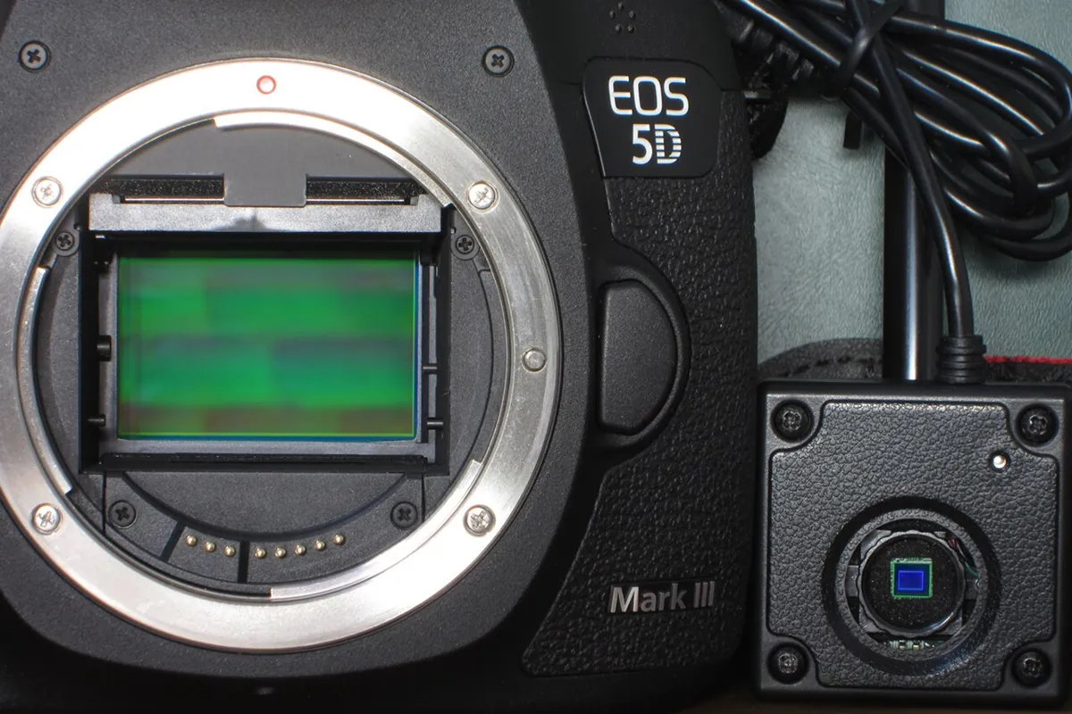
- Phone and laptop cameras: a CMOS sensor with a Bayer filter behind a small lens — the same parts as a robot webcam. Sensors come in many sizes; bigger photosites collect more light, which helps in a dim lab.
- Overhead camera for pick-and-place: fixing the camera straight above the table makes Z almost the same for every block, so pixel distance converts to centimetres with one number (Z / fx). That is why the Stage 11 capstone uses an overhead webcam.
- Fast conveyors: factory vision cameras often use global shutters and short exposures with bright lights so moving parts are not blurred or slanted.
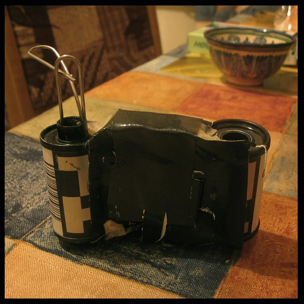
- Pinhole cameras: a matchbox with a pin-prick hole and a piece of film is a real camera with no lens at all — it proves the pinhole model is not just maths.
Think
Think about it
Think
You mount the webcam 50 cm above the table and see a 5 cm block as 60 px wide. Then you stack the block on a 20 cm box (so it is now 30 cm from the camera). How wide will it look, and what goes wrong if your code still assumes the table is 50 cm away?
Experiment
Try it in the lab
About 50 minutes. Python part needs NumPy (and optionally OpenCV); camera part needs a webcam, a ruler and an object of known width (a 10 cm scale or a book); bench part needs an Arduino UNO, a photocell and a 10 kΩ resistor.
Experiment
Pixels, distance and exposure
You will need
- `pinhole_projection.py` (NumPy; OpenCV optional)
- `camera_check.py` with `opencv-python` and a webcam
- Measuring tape, an object of known width
- Projection lab (in your browser)
- Bench: Arduino UNO, photocell, 10 kΩ resistor, black paper or a matchbox
Steps
- Run `pinhole_projection.py`. Change `FX` to 400 and run again. What happens to the block width and the FOV?
- In Part 3, pick a point on the same ray at Z = 240 cm. Predict its pixel before running.
- Run `camera_check.py`. Note the real resolution and FPS. Repeat with the lights dimmed.
- Hold your 10 cm object at 40, 60 and 80 cm from the lens. Measure its width in pixels each time (open the saved image in any viewer) and compute fx with `--fx-from`. Are the three fx values close?
- In the projection lab, set Z near and far and watch how the same board changes size.
- Bench: run `one_pixel_exposure.ino`, compare noise for 1, 8 and 64 readings, then wave your hand during the long exposure.
Interactive · Camera calibration lab · Educational
Intrinsics K map rays to pixels; bad fx / unmodeled distortion raise reprojection residual. Projection collapses Z — robots recover depth later. Estimates are educational, not a real OpenCV calibration runtime.
A camera turns a ray direction into a pixel. Divide by distance and you get the image position; multiply by distance and you get back centimetres — but only if you know the distance. Longer exposure means less noise but more blur.
Knowledge check
Check your understanding
Knowledge check
1. In the pinhole model, u = …
2. A 5 cm block looks 60 px wide at 50 cm. At 100 cm it looks…
3. Why can one camera not tell a small near block from a big far block?
4. You switch the same camera from 640×480 to 1280×960. fx, fy, cx, cy should…
5. In a Bayer filter, which colour has the most filter squares?
6. A longer exposure time gives…
7. A fast propeller looks bent in a cheap webcam video. The likely cause is…
8. With fx = 600 px, how much table does one pixel cover at Z = 60 cm?
Mini assignment
Hands-on assignment
Mini assignment
Your webcam’s “ID card”
Measure your camera and write down the numbers every later Stage 11 lesson will use.
Deliverables
- Real resolution and FPS from `camera_check.py`, in bright and dim light.
- Three fx estimates (object at three distances) and their average; the matching horizontal FOV.
- For your planned camera height above the arm’s table: block width in pixels for a 3 cm and a 5 cm block, and mm per pixel.
- A sketch: camera, lens centre, image plane, a block, its ray and its pixel (u, v), with Z marked.
- Optional (bench): a table of value and noise for 1, 8 and 64 readings from `one_pixel_exposure.ino`.
Do this, step by step
- Run
camera_check.pyin bright light and in dim light; write the real resolution and FPS each time. - Hold a 10 cm object at 40, 60 and 80 cm, measure its width in pixels and run
--fx-fromfor each. - Average the three fx values and compute the horizontal FOV = 2·atan(W / (2·fx)), where W is the image width in pixels.
- For your camera height Z, compute mm per pixel = Z / fx and the pixel width of a 3 cm and a 5 cm block.
- Draw the camera, lens centre, image plane, a block, its ray and its pixel (u, v), and mark Z.
Stuck? Hints, one at a time
- fx = (width in pixels × distance) / real width. A 10 cm object 120 px wide at 50 cm gives fx = 600 px.
- If the three fx values differ by more than about 10%, measure the distance from the lens, not from the back of the webcam.
- If the FPS drops in dim light, the camera is using a longer exposure — this is normal for auto-exposure webcams.
Challenges (pick by level)
- 🟢 Beginner: Add a function
cm_per_px(Z)topinhole_projection.pyand print it for Z = 30, 45 and 60 cm. - 🟡 Intermediate: Write
back_project(u, v, Z)that returns (X, Y) — the inverse ofproject. Check that projecting then back-projecting gives the original point. - 🟠 Advanced: Project all 8 corners of a 5 × 5 × 5 cm cube 40 cm in front of the camera and draw the edges with
cv.lineon a black 640 × 480 image. Move the cube left and see perspective. - 🔴 Expert: Add radial distortion
x″ = x′(1 + k1·r²)(from the OpenCV calib3d docs) with k1 = −0.2 and draw a straight grid. Do you get barrel or pincushion distortion? - ⚫ Research: Compare rolling-shutter and global-shutter sensors for a robot sorting items on a fast conveyor. Write half a page with sources.
Next step
You now know how light becomes a grid of pixels. In Lesson 3 — Images, Pixels & Color Spaces you will open that grid in Python: rows and columns, uint8 values, BGR vs RGB, grayscale, and why HSV makes colour detection much more robust to lighting.
Sources
- OpenCV 4.x — Camera Calibration and 3D Reconstruction (calib3d) — pinhole model u = fx·Xc/Zc + cx, intrinsic matrix, fx = f_mm / pixel size, f = sensor size / (2·tan(fov/2)), scaling intrinsics with resolution, radial (barrel/pincushion) distortion, all points on a ray map to one pixel,
projectPoints. - OpenCV 4.x — Getting Started with Videos (Python) —
VideoCapture,isOpened(),read(),CAP_PROP_FRAME_WIDTH/HEIGHTwithset/get. - Wikipedia — Pinhole camera model — ideal pinhole mapping, no lens distortion or blur, first-order approximation.
- Wikipedia — Camera obscura — light through a small hole projects an inverted, reversed image.
- Wikipedia — Bayer filter — colour filter array, half green, quarter red, quarter blue, Bryce Bayer of Eastman Kodak.
- Wikipedia — Rolling shutter — scanning capture vs global shutter, distortion of fast-moving objects.
- Adafruit — Using a Photocell — voltage divider with a 10 kΩ pull-down.
- Photos: Wikimedia Commons (credits under each image).
Look back: Lesson 1: Why Robots Need Vision. Next: Lesson 3: Images, Pixels & Color Spaces. Related: Stage 11 — Computer Vision, Stage 13 — Perception, Planning & Manipulation.
Self-attested for now — keep artifacts in your lab notebook.
Complete
Today's goal
0 of 1 done today
Mark this lesson complete when you have worked the experiment, knowledge check, and assignment (even roughly).