
Robot Simulation & Digital Twin · Lesson 04
Links, Joints & Robot Structure
Est. 55–70 min
Why
Why this lesson matters
In Lesson 3 you learnt to write a robot down as links and joints. This lesson is about the design choice behind that file: how many joints, what type, in what order, with what limits. That choice — the robot’s structure — decides where the tool can go, how many ways it can get there, and how hard it is to control. A simulator is the cheapest place to try different structures before you cut a single piece of metal.
You will count degrees of freedom on real robots, map the reach of four different arm structures with a Python script, and build a cardboard arm with potentiometers as joints so the Arduino can tell you where its tip is — a physical model you move by hand.
Concept
Structure: chains, trees, loops and degrees of freedom
1. Links, joints and degrees of freedom
A link is a rigid body; a joint lets two links move relative to each other in a limited way. A degree of freedom (DOF) is one independent number you need to describe the position. A train on a track has 1 DOF — distance along the track is enough. A free rigid body in space has at most 6 DOF: 3 translations (forward/back, left/right, up/down) and 3 rotations (roll, pitch, yaw).
| Joint | DOF it adds | Moves the child by… | Seen in |
|---|---|---|---|
| Revolute (hinge) | 1 | turning about one axis, between limits | Servo joints, elbows, doors |
| Prismatic (slider) | 1 | sliding along one axis, between limits | Linear rails, 3D-printer axes, lifts |
| Continuous | 1 | turning without limits | Wheels |
| Fixed | 0 | nothing — it just attaches a frame | Camera mount, tool tip |

2. Your own arm is the best teacher
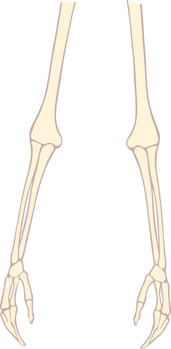
A human arm is usually counted as 7 DOF: 3 at the shoulder, 1 at the elbow and 3 at the wrist. That is one more than the 6 needed to place the hand anywhere in any orientation — so you can keep your hand still on the table and still move your elbow. That spare DOF is called redundancy; it lets you reach around obstacles. Most factory arms stop at 6.
3. Chains, trees and loops
Links joined by joints form a kinematic chain. How they are connected is the topology of the robot:
- Serial (open) chain: one link after another, base to tool. Most robot arms, including our desk arm. Easy to describe (a URDF is made for this) and easy to compute forward kinematics: just multiply joint by joint.
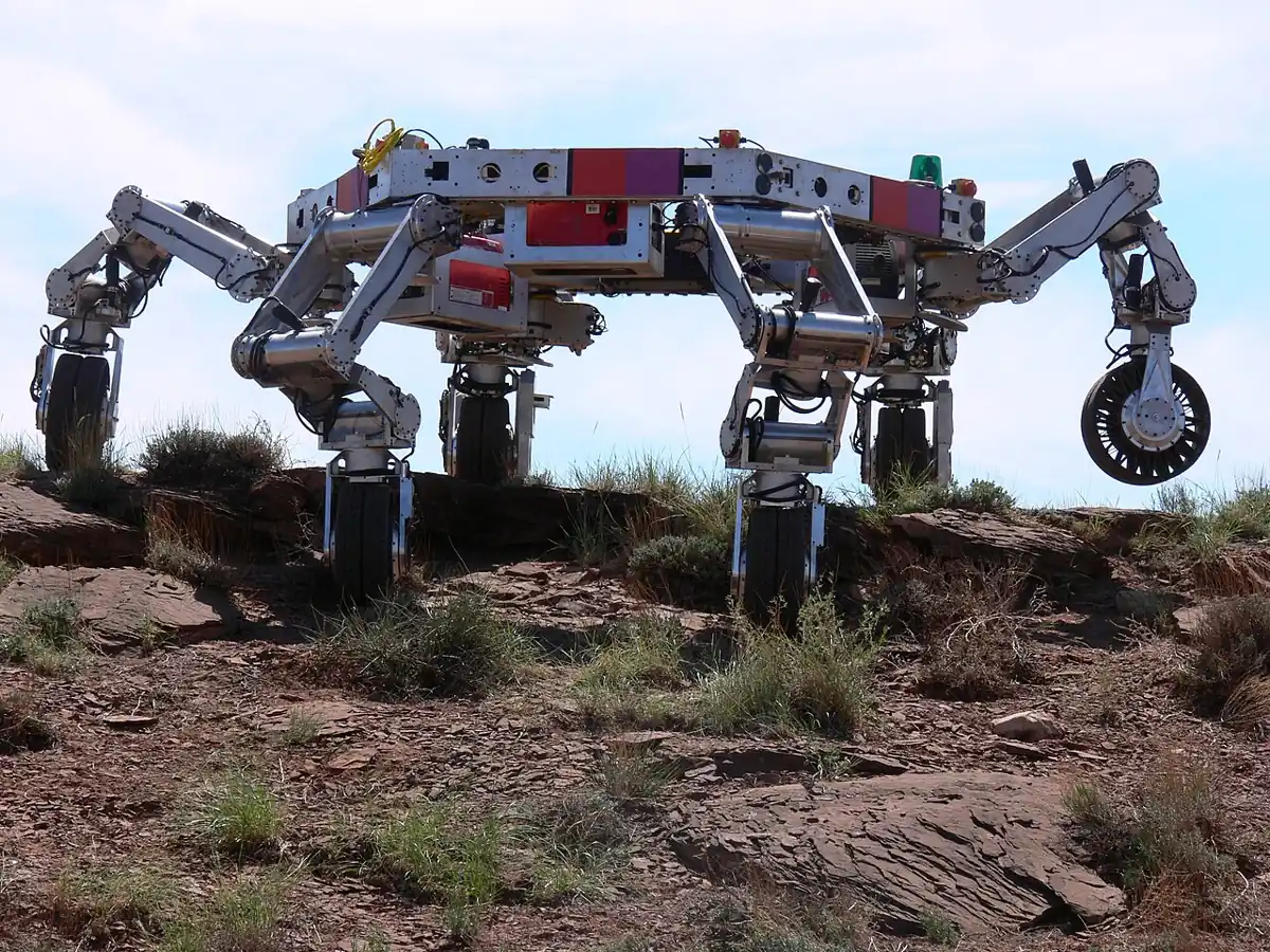
- Tree: chains that branch from one root. A humanoid, a two-armed robot, a walking robot with six legs. Still fine for URDF, because each link has one parent.
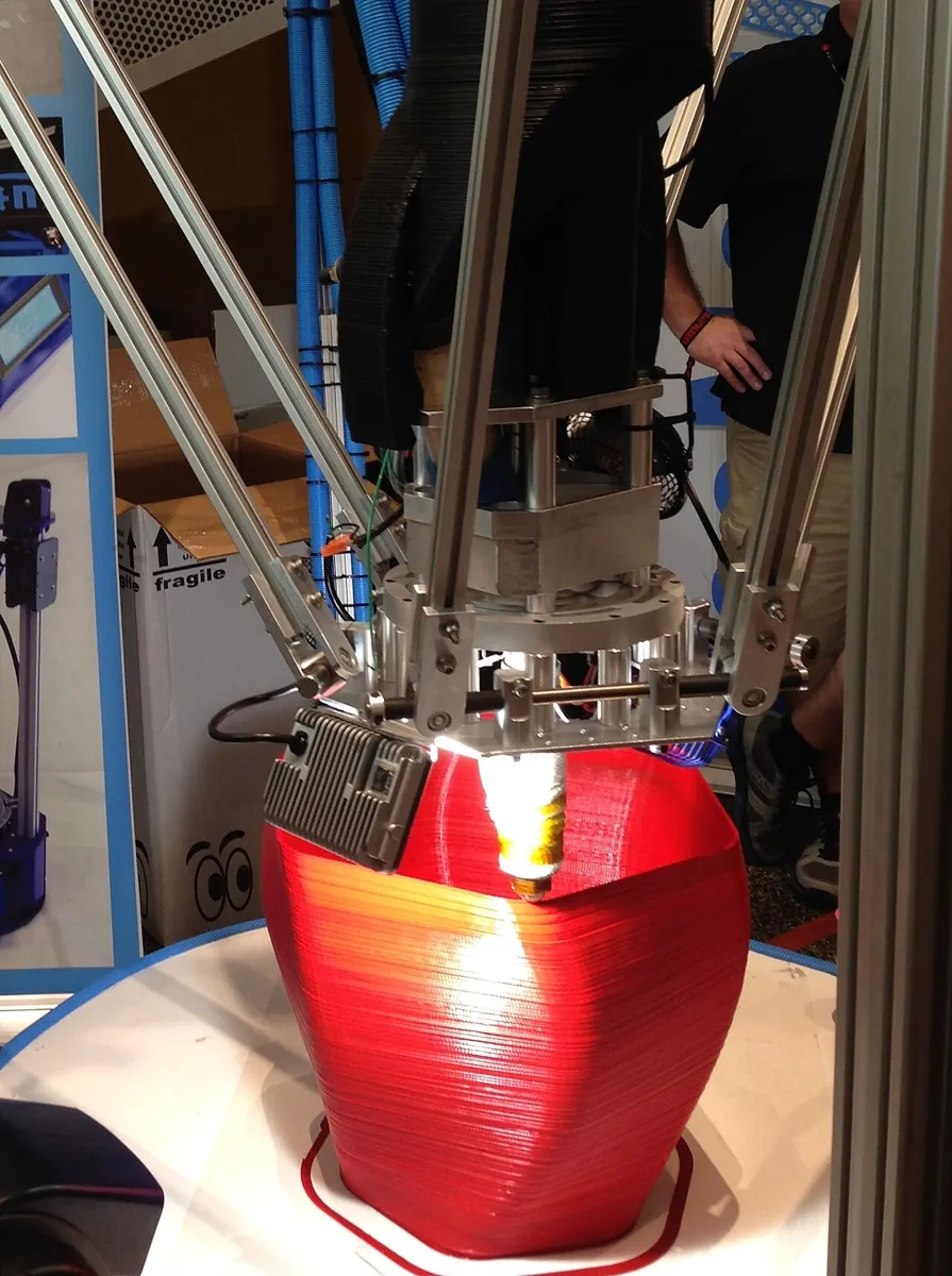
- Closed chain (parallel robot): links form a loop, so the tool is held by several chains at once. Delta robots and Stewart platforms. Very stiff and fast, but smaller reach — and a plain URDF tree cannot describe the loop directly.
4. Structure decides the workspace
The workspace is the set of all places the tool tip can reach. It depends on three things: link lengths (how far), joint types and order (which directions) and joint limits (how much of each direction). Change any one of them and the shape of the workspace changes — sometimes it even grows a hole where the arm cannot fold back far enough to reach close to its own base.
Visual
Visualise it: change the structure, change the robot
Educational URDF-style builder: add links and joints, switch joint types and limits, and see the structure as a tree. (Not production URDF or Xacro.)
Interactive · URDF robot builder · Educational (not production URDF)


base_link
Root / base — usually fixed to world in teaching models.
link_1
link_2
ee_link
<!-- educational pseudo-URDF — NOT production -->
<robot name="toy_arm">
  <link name="base_link"/>
  <link name="link_1"/>
  <joint name="j1" type="revolute">
    <parent link="base_link"/>
    <child link="link_1"/>
  </joint>
  <link name="link_2"/>
  <joint name="j2" type="revolute">
    <parent link="link_1"/>
    <child link="link_2"/>
  </joint>
  <link name="ee_link"/>
  <joint name="j3" type="fixed">
    <parent link="link_2"/>
    <child link="ee_link"/>
  </joint>
</robot>
Educational browser builder — not production URDF/Xacro, not Gazebo spawn, not Isaac articulation. Full robot description → planned Stage 19.
Code lab
Code lab: map the reach of four structures
workspace_map.py takes the shoulder and elbow of our desk arm (upper arm 0.12 m, forearm 0.10 m, shoulder 0.08 m above the table) and tries thousands of joint-angle combinations inside the limits. Every tip position that stays above the table is marked on a 2 cm grid (side view). It compares four structures: A the basic arm, B the same arm with a wider elbow, C A on a prismatic rail, D A with a wrist link. Run python3 workspace_map.py — only the standard library is used.
"""workspace_map.py - Stage 12 Lesson 4: structure decides what a robot can reach.

Side view (x forward, z up) of a desk arm's shoulder + elbow (+ wrist).
We try thousands of joint-angle combinations inside the joint limits, mark
every tip position on a grid, and compare four STRUCTURES:
  A  shoulder + elbow, elbow limited to +-90 deg   (2 DOF)
  B  same links, elbow allowed +-150 deg           (2 DOF, wider joint)
  C  A + a prismatic rail under the base (0..0.15 m) (3 DOF)
  D  A + a wrist link 0.06 m                         (3 DOF)
For each: degrees of freedom, how much area it covers, and whether it can
reach 4 test targets. Only the standard library:  python3 workspace_map.py
"""
import math

SHOULDER_Z = 0.08      # m, shoulder axis above the table
L1, L2, L3 = 0.12, 0.10, 0.06
CELL = 0.02            # m, grid cell for the map
TARGETS = {"cup on table": (0.18, 0.03), "shelf": (0.10, 0.30),
           "far bin": (0.30, 0.05), "rear tray": (-0.12, 0.10)}


def frange(lo, hi, step):
    n = int(round((hi - lo) / step))
    return [lo + i * (hi - lo) / n for i in range(n + 1)]


def tips(structure):
    """Yield every (x, z) tip position the structure can reach (sampled)."""
    sh = frange(math.radians(-80), math.radians(80), math.radians(4))
    el_lim = 150 if structure == "B" else 90
    el = frange(math.radians(-el_lim), math.radians(el_lim), math.radians(4))
    rail = frange(0.0, 0.15, 0.01) if structure == "C" else [0.0]
    wr = frange(math.radians(-90), math.radians(90), math.radians(10)) if structure == "D" else [None]
    for d in rail:
        for a in sh:
            for b in el:
                for c in wr:
                    # angles measured from straight up, positive = lean forward
                    x = d + L1 * math.sin(a) + L2 * math.sin(a + b)
                    z = SHOULDER_Z + L1 * math.cos(a) + L2 * math.cos(a + b)
                    if c is not None:
                        x += L3 * math.sin(a + b + c)
                        z += L3 * math.cos(a + b + c)
                    if z >= 0.0:                       # the table is solid
                        yield x, z


def cells(structure):
    return {(round(x / CELL), round(z / CELL)) for x, z in tips(structure)}


def reachable(cellset, target):
    cx, cz = round(target[0] / CELL), round(target[1] / CELL)
    return (cx, cz) in cellset


def draw(cellset):
    xs = range(-12, 24)                # -0.24 .. +0.46 m
    zs = range(19, -1, -1)             # 0.38 .. 0 m
    tcells = {(round(x / CELL), round(z / CELL)): k[0].upper() for k, (x, z) in TARGETS.items()}
    for zc in zs:
        row = ""
        for xc in xs:
            if (xc, zc) in tcells:
                row += tcells[(xc, zc)]
            elif xc == 0 and zc <= round(SHOULDER_Z / CELL):
                row += "|"
            else:
                row += "#" if (xc, zc) in cellset else "."
        print("   " + row)
    print("   " + "=" * len(xs) + "  table (z = 0); | = base; letters = targets")


DESC = {"A": "shoulder + elbow (+-90)", "B": "shoulder + elbow (+-150)",
        "C": "A + prismatic rail 0-0.15 m", "D": "A + wrist link 0.06 m"}
DOF = {"A": 2, "B": 2, "C": 3, "D": 3}

results = {}
for s in "ABCD":
    cs = cells(s)
    results[s] = cs
    print(f"Structure {s}: {DESC[s]}  ->  {DOF[s]} DOF, covers {len(cs) * CELL * CELL * 1e4:.0f} cm^2")
    if s in "AC":
        draw(cs)
    print()

print("target reach (Y = yes, - = no)")
print(f"   {'target':14s} {'x,z (m)':12s} " + "  ".join(s for s in "ABCD"))
for name, t in TARGETS.items():
    marks = "  ".join("Y" if reachable(results[s], t) else "-" for s in "ABCD")
    print(f"   {name:14s} {t[0]:+.2f},{t[1]:.2f}   {marks}")
print()
print("notes")
print("   More DOF is not automatically better: B reaches more with the SAME 2 DOF,")
print("   just by allowing a wider elbow. C trades a rail (cost, length) for reach.")
print("   A has a 'hole' around the base: with the elbow limited to +-90 deg the tip")
print("   can never come closer than about 0.16 m to the shoulder - so the rear tray")
print("   is out of reach until the structure changes (B, C or D).")
Output (run with python3 workspace_map.py)
Structure A: shoulder + elbow (+-90)  ->  2 DOF, covers 624 cm^2
   ....................................
   ....................................
   ....................................
   ....................................
   .........#######.S..................
   .......###########..................
   .....###############................
   ....#################...............
   ...#######.....#######..............
   ...#####.........#####..............
   ..#####...........#####.............
   ..#####...........#####.............
   .#####.............#####............
   .#####.............#####............
   .####.R.............####............
   .####.......|.......####............
   .####.......|.......####............
   ..####......|......##C#....F........
   ...###......|......###..............
   ....##......|......##...............
   ====================================  table (z = 0); | = base; letters = targets

Structure B: shoulder + elbow (+-150)  ->  2 DOF, covers 1076 cm^2

Structure C: A + prismatic rail 0-0.15 m  ->  3 DOF, covers 1448 cm^2
   ....................................
   ....................................
   ....................................
   ....................................
   .........########S######............
   .......###################..........
   .....######################.........
   ....########################........
   ...##########################.......
   ...#############.#############......
   ..#############...############......
   ..############....#############.....
   .############......############.....
   .############......############.....
   .#####R######.......###########.....
   .###########|.......###########.....
   .###########|.......###########.....
   ..##########|......##C#####F###.....
   ...#########|......###########......
   ....########|#.....#########........
   ====================================  table (z = 0); | = base; letters = targets

Structure D: A + wrist link 0.06 m  ->  3 DOF, covers 1492 cm^2

target reach (Y = yes, - = no)
   target         x,z (m)      A  B  C  D
   cup on table   +0.18,0.03   Y  Y  Y  Y
   shelf          +0.10,0.30   -  -  Y  Y
   far bin        +0.30,0.05   -  -  Y  -
   rear tray      -0.12,0.10   -  Y  Y  Y

notes
   More DOF is not automatically better: B reaches more with the SAME 2 DOF,
   just by allowing a wider elbow. C trades a rail (cost, length) for reach.
   A has a 'hole' around the base: with the elbow limited to +-90 deg the tip
   can never come closer than about 0.16 m to the shoulder - so the rear tray
   is out of reach until the structure changes (B, C or D).
Try it: build structure A, then change a joint type to prismatic or widen a limit, and watch how the tree and the model change. (Educational URDF-style builder, not production URDF.)
Interactive · URDF robot builder · Educational (not production URDF)
base_link
Root / base — usually fixed to world in teaching models.
link_1
link_2
ee_link
<!-- educational pseudo-URDF — NOT production -->
<robot name="toy_arm">
  <link name="base_link"/>
  <link name="link_1"/>
  <joint name="j1" type="revolute">
    <parent link="base_link"/>
    <child link="link_1"/>
  </joint>
  <link name="link_2"/>
  <joint name="j2" type="revolute">
    <parent link="link_1"/>
    <child link="link_2"/>
  </joint>
  <link name="ee_link"/>
  <joint name="j3" type="fixed">
    <parent link="link_2"/>
    <child link="ee_link"/>
  </joint>
</robot>
Educational browser builder — not production URDF/Xacro, not Gazebo spawn, not Isaac articulation. Full robot description → planned Stage 19.
Bench build: a cardboard arm with pot joints
Before buying motors, build the structure as a physical model. Cut an upper arm (12 cm between pivot holes) and a forearm (10 cm) from thick cardboard or ice-cream sticks. At the shoulder and elbow, glue each link to the shaft of a 10 kΩ potentiometer, so turning the joint turns the pot. pot_arm_fk.ino reads both angles, runs the same forward kinematics as the Python script, and tells you the tip position and whether you broke a limit.
| Part | Connection | Note |
|---|---|---|
| Shoulder pot (10 kΩ) | outer legs to 5V and GND, wiper (middle) to A0 | pots draw well under 1 mA — safe on the 5V pin |
| Elbow pot (10 kΩ) | outer legs to 5V and GND, wiper to A1 | keep wires long and loose so the joint can turn |
| USB | Arduino ↔ laptop | Serial Monitor or Serial Plotter at 115200 |
// pot_arm_fk.ino - Stage 12 Lesson 4: a cardboard arm whose joints are pots.
// Build a 2-link arm from cardboard or ice-cream sticks: the shoulder and the
// elbow each turn the shaft of a potentiometer. The Arduino reads both angles,
// does forward kinematics with the SAME lengths as workspace_map.py, and warns
// when a joint passes its limit or the tip goes into the table.
// No motors at all: this is a hand-moved "physical model" of the structure.
// Wiring: each 10k pot: outer legs to 5V and GND, wiper -> A0 (shoulder), A1 (elbow).
// Serial Monitor 115200.

const float SHOULDER_Z = 0.08;   // m
const float L1 = 0.12;           // m, shoulder -> elbow
const float L2 = 0.10;           // m, elbow -> tip
const float POT_TRAVEL = 270.0;  // deg over 0..1023 - check your pot, then calibrate
const int SHOULDER_MID = 512;    // raw reading when the upper arm points straight up
const int ELBOW_MID = 512;       // raw reading when the forearm is straight
const float SHOULDER_LIM = 80.0; // deg, same limits as structure A
const float ELBOW_LIM = 90.0;

float potToDeg(int raw, int mid) {
  return (raw - mid) * (POT_TRAVEL / 1023.0);
}

void setup() {
  Serial.begin(115200);
  Serial.println(F("shoulder_deg,elbow_deg,x_m,z_m,status"));
}

void loop() {
  float a = potToDeg(analogRead(A0), SHOULDER_MID);
  float b = potToDeg(analogRead(A1), ELBOW_MID);
  float ar = radians(a);
  float br = radians(a + b);
  float x = L1 * sin(ar) + L2 * sin(br);
  float z = SHOULDER_Z + L1 * cos(ar) + L2 * cos(br);

  const __FlashStringHelper* status = F("OK");
  if (fabs(a) > SHOULDER_LIM) status = F("SHOULDER LIMIT");
  else if (fabs(b) > ELBOW_LIM) status = F("ELBOW LIMIT");
  else if (z < 0.0) status = F("IN THE TABLE");

  Serial.print(a, 0); Serial.print(',');
  Serial.print(b, 0); Serial.print(',');
  Serial.print(x, 3); Serial.print(',');
  Serial.print(z, 3); Serial.print(',');
  Serial.println(status);
  delay(100);   // 10 lines per second is plenty for a hand-moved arm
}shoulder_deg,elbow_deg,x_m,z_m,status
0,0,0.000,0.300,OK
30,60,0.160,0.184,OK
70,85,0.155,0.030,OK
40,100,0.141,0.095,ELBOW LIMIT
-85,0,-0.219,0.099,SHOULDER LIMITDebugging
| Symptom | Likely cause | Fix |
|---|---|---|
| Angle jumps around when nothing moves | loose wiper wire or breadboard contact | Solder or press-fit the wires; average 4 readings |
| Angle goes the wrong way | pot outer legs swapped | Swap 5V and GND on that pot, or negate the angle |
| Tip position wrong by a constant angle | *_MID not calibrated | Redo the straight-up calibration |
| Tip position wrong by a scale | link lengths or POT_TRAVEL wrong | Measure pivot to pivot; check the pot’s rotation angle |
| Python map looks empty | grid cell too big or limits typed in degrees where radians are used | Keep math.radians() around every limit |
Real world
Robot structures in the real world
- Factory arms: six-axis industrial robots are serial chains of six revolute joints — exactly enough DOF to place a tool at any position and orientation inside their workspace.
- Space arms: the Space Shuttle’s arm used shoulder, elbow and wrist joints to capture and move payloads; with rigid booms, it could only move the payload in directions its joint rotations allowed.
- Parallel machines: delta robots and delta 3D printers hold the tool with several chains at once. Stiff and fast, ideal for pick-and-place lines and printing.
- Walking robots: NASA JPL’s ATHLETE rover has six legs, each a serial chain with a wheel at the end — a branching tree of chains from one body.
Think
Think about it
Think
A student says: “A 7-DOF arm is always better than a 6-DOF arm, and a 6-DOF arm is always better than a 4-DOF one.” Do you agree?
Experiment
Try it in the lab
About 55 minutes. The Python part needs only Python 3. The bench part needs an Arduino UNO, two 10 kΩ potentiometers, cardboard and glue.
Experiment
Count, map, build, compare
You will need
- `workspace_map.py` (Python 3, no libraries)
- URDF robot builder (in your browser)
- Arduino UNO, two 10 kΩ rotary potentiometers, jumper wires
- Thick cardboard or ice-cream sticks, glue, ruler, protractor
Steps
- Count DOF: your own arm (move only the shoulder, then only the elbow, then only the wrist), a ceiling fan, a drawer, a door, a desk lamp. Write the joint type for each.
- Run `workspace_map.py`. Find the hole in structure A and explain it with √(L1² + L2²).
- Change `L2` to 0.12 m and re-run. Does A still have a hole? Does the area grow?
- Add a structure E: A with the shoulder limited to 0…80° (forward only). Which targets disappear?
- In the URDF builder, build structure C (a prismatic rail under the shoulder) and check the tree has one root.
- Bench: build the cardboard arm, calibrate, then move it to the cup target (0.18, 0.03). Does the Serial Monitor agree with the ruler?
Interactive · URDF robot builder · Educational (not production URDF)
base_link
Root / base — usually fixed to world in teaching models.
link_1
link_2
ee_link
<!-- educational pseudo-URDF — NOT production -->
<robot name="toy_arm">
  <link name="base_link"/>
  <link name="link_1"/>
  <joint name="j1" type="revolute">
    <parent link="base_link"/>
    <child link="link_1"/>
  </joint>
  <link name="link_2"/>
  <joint name="j2" type="revolute">
    <parent link="link_1"/>
    <child link="link_2"/>
  </joint>
  <link name="ee_link"/>
  <joint name="j3" type="fixed">
    <parent link="link_2"/>
    <child link="ee_link"/>
  </joint>
</robot>
Educational browser builder — not production URDF/Xacro, not Gazebo spawn, not Isaac articulation. Full robot description → planned Stage 19.
The same two links give very different reach depending on joint limits and on what extra joint you add. Numbers from the script, the cardboard model and the ruler should agree to about a centimetre — if not, a length, a calibration or a limit is wrong.
Knowledge check
Check your understanding
Knowledge check
1. How many DOF does a free rigid body in 3D space have at most?
2. How many DOF does one revolute or prismatic joint add?
3. A human arm is usually counted as 7 DOF. Why is that useful?
4. A delta robot holds its tool with several chains at once. Its topology is…
5. In the script, structure B covers far more area than A with the same 2 DOF. What changed?
6. Why can structure A not reach the rear tray close to its base?
7. Is it safe to power the two potentiometers in the bench build from the Arduino 5V pin?
Mini assignment
Hands-on assignment
Mini assignment
Choose a structure for a real task
Pick a task on your desk, decide the simplest arm structure that can do it, and prove it with the workspace map and the cardboard model.
Deliverables
- A sketch of your task area with 3 target points (x, z) measured with a ruler.
- A new structure added to `workspace_map.py` (your link lengths and limits) and its output showing all 3 targets reachable.
- A DOF count and a one-line reason for every joint you kept — and one joint you decided **not** to add.
- Bench: Serial Monitor lines from the cardboard arm at each target, with the ruler values next to them.
Do this, step by step
- Draw your task area and mark 3 target points (x, z), measured with a ruler.
- Add your own structure to
workspace_map.pywith your link lengths and limits. - Put your 3 points in
TARGETSand run it until all 3 are reachable (or change the design). - Count the DOF and write one reason for every joint you kept, and one you left out.
- Bench: move the cardboard arm (
pot_arm_fk.ino) to each target and log the Serial lines next to your ruler values.
Stuck? Hints, one at a time
SHOULDER_Zis the shoulder height above the table. Measure it on your arm, not from the example.- A target just outside the map can often be reached by moving the base closer, not by adding a joint.
- If the Serial x, z are mirrored, the pot is turning the opposite way. Flip the sign in the sketch, not the wiring.
Challenges (pick by level)
- 🟢 Beginner: Make a DOF table for 8 things at home (fan, tap, scissors, laptop lid…). Mark each joint as revolute, prismatic or fixed.
- 🟡 Intermediate: Add a
sweep_targets()function that prints, for each structure, the smallest change in one joint limit that makes a missing target reachable. - 🟠 Advanced: Add base yaw to structure A and compute the 3D workspace volume (in litres) by sweeping the side-view map around the vertical axis.
- 🔴 Expert: Add a third pot (wrist) to the cardboard arm and extend
pot_arm_fk.inoto print the gripper angle too. Compare with structure D. - ⚫ Research: Read the Wikipedia articles on kinematic chains and degrees of freedom. Write half a page on why parallel robots are stiffer but have a smaller workspace than serial arms.
Next step
You now know how a robot is built. In Lesson 5 — Simulation Worlds & Coordinate Frames you will place that robot into a world: ground, table, objects, and the coordinate frames that say where everything is.
Look back: Lesson 3: Robot Models & URDF Concepts. Next: Lesson 5: Simulation Worlds & Coordinate Frames. Related: Stage 8 — Kinematics & IK.
Sources
- Wikipedia — Degrees of freedom (mechanics)) — rigid body has at most 6 DOF (3 translations, 3 rotations); train on a track 1 DOF; human arm considered 7 DOF (3 shoulder, 1 elbow, 3 wrist); serial manipulator of six 1-DOF joints has 6 DOF.
- Wikipedia — Kinematic chain — rigid bodies connected by joints; serial, parallel and tree topologies; forward kinematics of serial chains; ATHLETE robot legs as serial chains.
- Lesson 3 sources (ROS 2 URDF tutorials) for joint types and limits.
- Photos: Wikimedia Commons (credits under each image). The human arm bones illustration is shown as a diagram.
Self-attested for now — keep artifacts in your lab notebook.
Complete
Today's goal
0 of 1 done today
Mark this lesson complete when you have worked the experiment, knowledge check, and assignment (even roughly).