
Robot Simulation & Digital Twin · Lesson 05
Simulation Worlds & Coordinate Frames
Est. 55–70 min
Why
Why this lesson matters
A simulation world is everything around the robot: the floor, the table, the objects, the lights, the cameras — and the physics settings that make them behave. Every one of those things has a pose (position + orientation), and every pose is measured from some frame. If the frames are wrong, a perfect motion planner sends the arm to the wrong place.
In this lesson you will read a small Gazebo-style world file, compute where a cup is from the world’s point of view, the camera’s and the arm’s, break it three classic ways, and then build an ultrasonic “radar” that turns its own readings into table coordinates on the Arduino.
Concept
Worlds, poses and frames
1. What is inside a simulation world?
| Part of the world | What it describes | In SDF (Gazebo) |
|---|---|---|
| Physics | Time step and speed of simulation | <physics> with <max_step_size> (e.g. 0.001 s) and <real_time_factor> (1.0 = as fast as real time) |
| Light | Sun, lamps — matter for cameras | <light type="directional"> with a pose and a direction |
| Ground and props | Floor, table, walls, cups | <model> with links, collision and visual shapes; <static>true</static> for things that never move |
| Robots | Your arm, loaded from its description | A model included or spawned into the world |
| Frames | Named places with no body: arm mount, camera, tool | <frame> with a <pose> |
2. A frame is a point of view
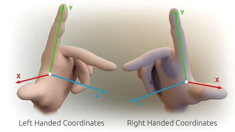
A coordinate frame is an origin plus three axes. The same cup has different numbers in different frames — like your house is “2 km east” from the station but “500 m north” from the school. ROS’s convention (REP 103) for a body is x forward, y left, z up, and SI units: metres and radians. This is a right-handed frame: point your right-hand index finger along x, middle finger along y, and your thumb gives z.
3. Pose = position + orientation
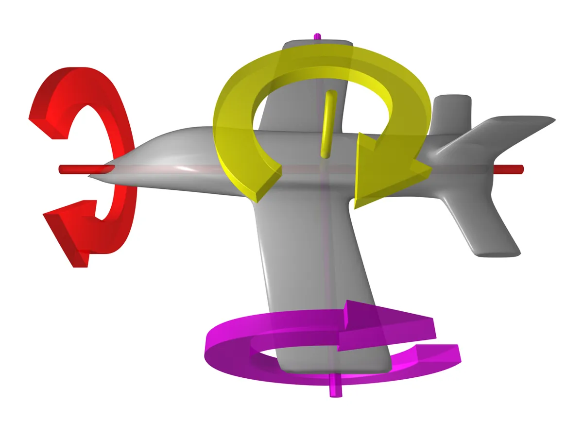
A pose has 6 numbers: x, y, z (metres) and roll, pitch, yaw (radians) — rotations about x, y and z. In SDF, <pose relative_to="table">0.05 0 0.05 0 0 0</pose> means “5 cm forward and 5 cm up from the table frame”. Without relative_to, the pose is measured from the world.
4. Frames form a tree, and you walk it
Each frame has one parent: cup ← table ← world, camera_optical ← camera ← table. To move a point from one frame to another, you walk the tree: up to the common parent, then down. Each step is a transform — a rotation plus a shift — and in code it is a 4×4 matrix. The order matters: “move then turn” is not the same as “turn then move”. ROS’s REP 105 uses the same idea for mobile robots: map → odom → base_link, one parent each.
Camera sees the cup
cup in
camera_optical= (0, −0.05, 0.80)Up to the world
multiply by world ← camera_optical: cup in world = (0.65, 0, 0.80)
Down to the arm
multiply by the inverse of world ← arm_base: cup in arm frame = (0.20, 0.15, 0.05)
Send to the planner
only now is the number in the frame the arm understands
Visual
Visualise it: walk through a simulation world
World and frames explorer: one scene, many frames. (Educational scene, not Gazebo worlds or Isaac stages.)
Interactive · Simulation world explorer · Educational


Origin of the scene. Everything else is relative to this frame.
Selected
world
Frame idea
origin
Physics
off (Part 1)
Browser educational world — not Gazebo/Ignition, not Isaac Sim, not MuJoCo, not real-time contacts.
Code lab
Code lab: read a world, chase a cup through frames
desk_world.sdf is a small teaching world in the layout of the Gazebo SDF tutorial: physics, a sun, a ground plane, a table (frame at the centre of its top, 0.75 m up), an arm_base frame, a cup and an overhead camera frame. Numbers are examples — measure your own desk.
<?xml version="1.0" ?>
<!-- desk_world.sdf - Stage 12 Lesson 5: a small teaching world for the desk arm.
     Tag layout follows the Gazebo "SDF worlds" tutorial. All poses are
     x y z roll pitch yaw, in metres and radians. Example numbers - measure yours. -->
<sdf version="1.8">
  <world name="desk_lab">
    <physics name="1ms" type="ignored">
      <max_step_size>0.001</max_step_size>
      <real_time_factor>1.0</real_time_factor>
    </physics>
    <plugin filename="gz-sim-physics-system" name="gz::sim::systems::Physics"></plugin>
    <plugin filename="gz-sim-user-commands-system" name="gz::sim::systems::UserCommands"></plugin>
    <plugin filename="gz-sim-scene-broadcaster-system" name="gz::sim::systems::SceneBroadcaster"></plugin>

    <light type="directional" name="sun">
      <cast_shadows>true</cast_shadows>
      <pose>0 0 10 0 0 0</pose>
      <diffuse>0.8 0.8 0.8 1</diffuse>
      <direction>-0.5 0.1 -0.9</direction>
    </light>

    <!-- the floor: z = 0 of the world frame -->
    <model name="ground_plane">
      <static>true</static>
      <link name="link">
        <collision name="collision">
          <geometry><plane><normal>0 0 1</normal></plane></geometry>
        </collision>
        <visual name="visual">
          <geometry><plane><normal>0 0 1</normal><size>10 10</size></plane></geometry>
        </visual>
      </link>
    </model>

    <!-- table: model frame at the CENTRE of the top surface, 0.75 m above the floor -->
    <model name="table">
      <static>true</static>
      <pose>0.60 0 0.75 0 0 0</pose>
      <link name="top">
        <collision name="collision">
          <pose>0 0 -0.02 0 0 0</pose>
          <geometry><box><size>0.80 0.60 0.04</size></box></geometry>
        </collision>
        <visual name="visual">
          <pose>0 0 -0.02 0 0 0</pose>
          <geometry><box><size>0.80 0.60 0.04</size></box></geometry>
        </visual>
      </link>
    </model>

    <!-- the arm's base sits near the left edge of the table, turned -90 deg to face the middle -->
    <frame name="arm_base">
      <pose relative_to="table">-0.10 0.20 0 0 0 -1.5708</pose>
    </frame>

    <!-- a cup on the table -->
    <model name="cup">
      <pose relative_to="table">0.05 0 0.05 0 0 0</pose>
      <link name="body">
        <inertial><mass>0.05</mass></inertial>
        <collision name="collision">
          <geometry><cylinder><radius>0.04</radius><length>0.10</length></cylinder></geometry>
        </collision>
        <visual name="visual">
          <geometry><cylinder><radius>0.04</radius><length>0.10</length></cylinder></geometry>
        </visual>
      </link>
    </model>

    <!-- overhead camera 0.85 m above the table top, x axis pointing straight down -->
    <frame name="camera">
      <pose relative_to="table">0 0 0.85 0 1.5708 0</pose>
    </frame>
  </world>
</sdf>
world_frames.py reads only the <pose> tags, builds the frame tree and does all the maths with plain 4×4 lists — no NumPy, no ROS. Put both files in one folder and run python3 world_frames.py.
"""world_frames.py - Stage 12 Lesson 5: where is the cup? Ask the frames.

Reads desk_world.sdf (only the <pose> of models and frames), builds the frame
tree, and answers one question three ways:
  1. where the cup is in the WORLD frame (from the world file),
  2. what the overhead camera sees (cup in the camera's OPTICAL frame),
  3. where the ARM must reach (cup in the arm_base frame) - from the camera.
Then it makes three classic frame mistakes on purpose and measures the damage.
Only the standard library:  python3 world_frames.py   (desk_world.sdf next to it)
"""
import math
import xml.etree.ElementTree as ET

# ---------- tiny 4x4 transform toolkit (lists, no numpy) ----------
def rpy_matrix(r, p, y):
    """Rotation for roll-pitch-yaw about FIXED axes: R = Rz(y) @ Ry(p) @ Rx(r)."""
    cr, sr, cp, sp, cy, sy = math.cos(r), math.sin(r), math.cos(p), math.sin(p), math.cos(y), math.sin(y)
    return [[cy * cp, cy * sp * sr - sy * cr, cy * sp * cr + sy * sr],
            [sy * cp, sy * sp * sr + cy * cr, sy * sp * cr - cy * sr],
            [-sp, cp * sr, cp * cr]]

def make_T(x, y, z, r, p, yaw):
    R = rpy_matrix(r, p, yaw)
    return [R[0] + [x], R[1] + [y], R[2] + [z], [0, 0, 0, 1]]

def mul(A, B):
    return [[sum(A[i][k] * B[k][j] for k in range(4)) for j in range(4)] for i in range(4)]

def inv(T):
    R = [row[:3] for row in T[:3]]
    t = [T[0][3], T[1][3], T[2][3]]
    Rt = [[R[j][i] for j in range(3)] for i in range(3)]
    ti = [-sum(Rt[i][k] * t[k] for k in range(3)) for i in range(3)]
    return [Rt[0] + [ti[0]], Rt[1] + [ti[1]], Rt[2] + [ti[2]], [0, 0, 0, 1]]

def apply(T, p):
    return [sum(T[i][k] * p[k] for k in range(3)) + T[i][3] for i in range(3)]

def fmt(p):
    return "(" + ", ".join(f"{v:+.3f}" for v in p) + ")"

# ---------- 1. read the world ----------
world = ET.parse("desk_world.sdf").getroot().find("world")
parent, local = {}, {}
for el in list(world.findall("model")) + list(world.findall("frame")):
    pose = el.find("pose")
    name = el.get("name")
    if pose is None:
        parent[name], local[name] = "world", make_T(0, 0, 0, 0, 0, 0)
        continue
    nums = [float(v) for v in pose.text.split()]
    parent[name] = pose.get("relative_to", "world")
    local[name] = make_T(*nums)

# camera_optical: z forward, x right, y down (REP 103 "_optical" frames)
parent["camera_optical"] = "camera"
local["camera_optical"] = make_T(0, 0, 0, -math.pi / 2, 0, -math.pi / 2)

def world_T(name):
    """Walk up the tree: world <- ... <- name."""
    T = make_T(0, 0, 0, 0, 0, 0)
    chain = []
    while name != "world":
        chain.append(name)
        T = mul(local[name], T)
        name = parent[name]
    return T, chain

print("frame tree (child <- parent)")
for name in parent:
    print(f"   {name:15s} <- {parent[name]}")
roots = [n for n in parent if parent[n] not in parent and parent[n] != "world"]
print("   every frame has exactly one parent; missing parents:", roots or "none")

T_w_cup, chain = world_T("cup")
cup_world = apply(T_w_cup, [0, 0, 0])
print("\n1. cup in WORLD frame (from the world file)")
print("   chain:", " -> ".join(["world"] + chain[::-1]))
print("   cup =", fmt(cup_world), "m   (table centre x 0.60, top at z 0.75, cup centre 5 cm up)")

# ---------- 2. what the camera sees ----------
T_w_opt, _ = world_T("camera_optical")
cup_opt = apply(inv(T_w_opt), cup_world)
print("\n2. cup in CAMERA_OPTICAL frame (what a vision node would report)")
print("   cup =", fmt(cup_opt), "m   (z = depth in front of the lens)")
print(f"   depth check: camera {0.75 + 0.85:.2f} m high, cup centre {cup_world[2]:.2f} m -> {0.75 + 0.85 - cup_world[2]:.2f} m")

# ---------- 3. where must the arm reach? ----------
T_w_arm, _ = world_T("arm_base")
cup_arm = apply(inv(T_w_arm), apply(T_w_opt, cup_opt))
print("\n3. cup in ARM_BASE frame (camera -> world -> arm)")
print("   cup =", fmt(cup_arm), "m   (x forward of the arm, y to its left, z up)")
print(f"   horizontal reach needed: {math.hypot(cup_arm[0], cup_arm[1]):.3f} m")

# ---------- 4. three classic mistakes ----------
def err(p):
    return math.dist(p, cup_arm) * 100

print("\n4. classic mistakes (error in cm at the gripper)")
# a) yaw of arm_base typed in degrees (90) instead of radians
T_bad = mul(local["table"], make_T(-0.10, 0.20, 0, 0, 0, -90))
p = apply(inv(T_bad), cup_world)
print(f"   a) arm yaw written as -90 (degrees) not -1.5708 -> {fmt(p)}  error {err(p):5.1f} cm")
# b) forgot the optical frame: treat optical numbers as camera-body numbers
T_w_cam, _ = world_T("camera")
p = apply(inv(T_w_arm), apply(T_w_cam, cup_opt))
print(f"   b) optical frame ignored (z-forward used as z-up) -> {fmt(p)}  error {err(p):5.1f} cm")
# c) transforms multiplied in the wrong order
T_wrong = mul(local["arm_base"], local["table"])
p = apply(inv(T_wrong), cup_world)
print(f"   c) table and arm_base multiplied in wrong order -> {fmt(p)}  error {err(p):5.1f} cm")

print("\nnotes")
print("   Every number in a simulator is 'in some frame'. Write the frame next to the")
print("   number (cup_in_arm, not just cup) and most of these bugs disappear.")
Output (run with python3 world_frames.py)
frame tree (child <- parent)
   ground_plane    <- world
   table           <- world
   cup             <- table
   arm_base        <- table
   camera          <- table
   camera_optical  <- camera
   every frame has exactly one parent; missing parents: none

1. cup in WORLD frame (from the world file)
   chain: world -> table -> cup
   cup = (+0.650, +0.000, +0.800) m   (table centre x 0.60, top at z 0.75, cup centre 5 cm up)

2. cup in CAMERA_OPTICAL frame (what a vision node would report)
   cup = (+0.000, -0.050, +0.800) m   (z = depth in front of the lens)
   depth check: camera 1.60 m high, cup centre 0.80 m -> 0.80 m

3. cup in ARM_BASE frame (camera -> world -> arm)
   cup = (+0.200, +0.150, +0.050) m   (x forward of the arm, y to its left, z up)
   horizontal reach needed: 0.250 m

4. classic mistakes (error in cm at the gripper)
   a) arm yaw written as -90 (degrees) not -1.5708 -> (+0.112, +0.224, +0.050)  error  11.5 cm
   b) optical frame ignored (z-forward used as z-up) -> (+0.250, +0.900, +0.850)  error 109.8 cm
   c) table and arm_base multiplied in wrong order -> (-0.400, +0.750, +0.050)  error  84.9 cm

notes
   Every number in a simulator is 'in some frame'. Write the frame next to the
   number (cup_in_arm, not just cup) and most of these bugs disappear.
Try it: move objects in the educational world, switch the frame you view them from, and watch the same object get different coordinates. (Educational scene, not a Gazebo or Isaac world.)
Interactive · Simulation world explorer · Educational
Origin of the scene. Everything else is relative to this frame.
Selected
world
Frame idea
origin
Physics
off (Part 1)
Browser educational world — not Gazebo/Ignition, not Isaac Sim, not MuJoCo, not real-time contacts.
Bench build: an ultrasonic radar that reports in table coordinates
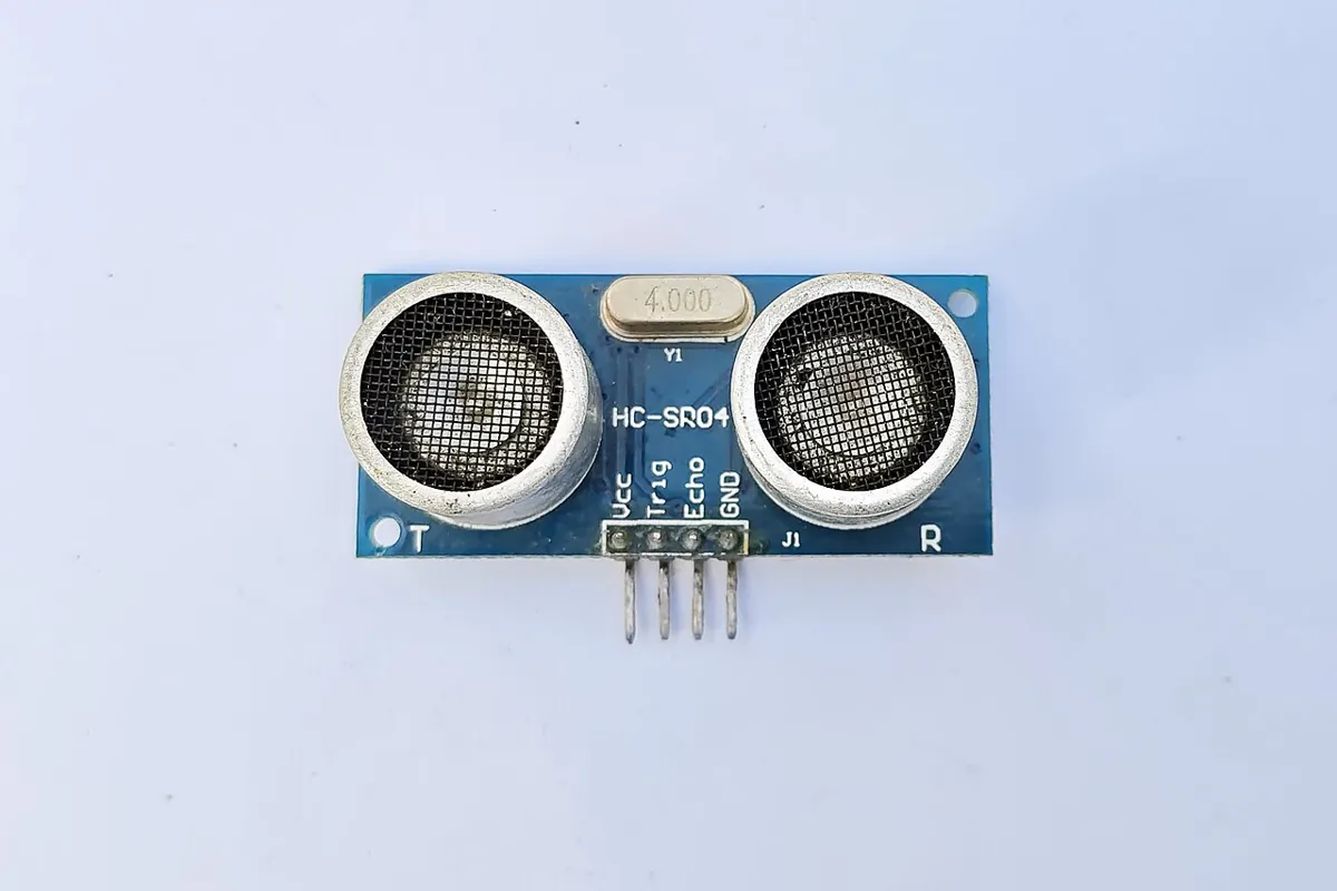
A distance sensor only knows “something is d metres in front of me” — a point in its own frame. Fix an HC-SR04 ultrasonic sensor on top of a potentiometer knob (the pan joint), place it at a measured spot on the table, and sonar_frames.ino converts every reading into the table frame: rotate by the pan angle, then shift by the sensor’s position. The same two steps your Python script did, on an 8-bit board.
| Part | Connection | Note |
|---|---|---|
| HC-SR04 VCC / GND | 5V / GND | a small sensor module; fine on the 5V pin |
| HC-SR04 TRIG | D7 | the Arduino sends a short pulse to start a ping |
| HC-SR04 ECHO | D8 | pulse length = time for the sound to go and come back |
| 10 kΩ pot (pan) | outer legs 5V and GND, wiper A0 | glue the sensor on the knob so turning it turns the sensor |
// sonar_frames.ino - Stage 12 Lesson 5: one reading, two frames.
// An HC-SR04 ultrasonic sensor sits on a hand-turned pot (a "pan" joint) at a
// known place on the table. The sensor measures distance along ITS OWN x axis.
// The Arduino converts every reading into the TABLE frame, exactly like a
// simulator or ROS turns sensor data into world coordinates.
// No motors. Wiring:
//   HC-SR04: VCC -> 5V, GND -> GND, TRIG -> D7, ECHO -> D8
//   10k pot (pan angle): outer legs -> 5V and GND, wiper -> A0
// Serial Monitor 115200. Table frame: x forward, y left, z up (metres).

const int TRIG = 7;
const int ECHO = 8;
// where the sensor's pan axis is, in the TABLE frame (measure yours)
const float SENSOR_X = -0.30;   // m
const float SENSOR_Y = 0.00;    // m
const float SENSOR_Z = 0.05;    // m, height of the sensor above the table
const int PAN_MID = 512;        // raw pot value when the sensor faces table +x
const float POT_TRAVEL = 270.0; // deg over 0..1023 - check your pot

float readDistanceM() {
  digitalWrite(TRIG, LOW);
  delayMicroseconds(2);
  digitalWrite(TRIG, HIGH);
  delayMicroseconds(10);
  digitalWrite(TRIG, LOW);
  unsigned long us = pulseIn(ECHO, HIGH, 30000UL);   // ~5 m max, 30 ms timeout
  if (us == 0) return -1.0;                           // no echo
  return us * 0.000343 / 2.0;                         // speed of sound ~343 m/s
}

void setup() {
  Serial.begin(115200);
  pinMode(TRIG, OUTPUT);
  pinMode(ECHO, INPUT);
  Serial.println(F("pan_deg,d_sensor_m,x_table_m,y_table_m,z_table_m"));
}

void loop() {
  float pan = (analogRead(A0) - PAN_MID) * (POT_TRAVEL / 1023.0);  // + = turn left
  float d = readDistanceM();
  Serial.print(pan, 0); Serial.print(',');
  if (d < 0) {
    Serial.println(F("no echo,-,-,-"));
  } else {
    // point (d, 0, 0) in the sensor frame -> rotate by pan about z -> shift to sensor position
    float a = radians(pan);
    float x = SENSOR_X + d * cos(a);
    float y = SENSOR_Y + d * sin(a);
    Serial.print(d, 3); Serial.print(',');
    Serial.print(x, 3); Serial.print(',');
    Serial.print(y, 3); Serial.print(',');
    Serial.println(SENSOR_Z, 3);
  }
  delay(100);   // HC-SR04 needs time between pings; 10 per second is fine
}pan_deg,d_sensor_m,x_table_m,y_table_m,z_table_m
0,0.350,0.050,0.000,0.050
30,0.400,0.046,0.200,0.050
-45,0.283,-0.100,-0.200,0.050
12,no echo,-,-,-Debugging
| Symptom | Likely cause | Fix |
|---|---|---|
| Object appears mirrored left–right | left-handed frame or a flipped y sign | Check x forward, y left, z up with the right-hand rule |
| Object far up in the air / below the floor | camera optical z used as world z | Convert optical → camera → world |
| Error grows when the base is turned | yaw in degrees, or rotation applied after the shift | Use radians; rotate first, then add the position |
| Everything is off by a fixed amount | frame origin measured from the wrong place (table edge vs centre) | Write in the file where each frame’s origin is |
| “no echo” every time | sensor too close (few cm), soft target, or TRIG/ECHO swapped | Use a hard flat box 10–100 cm away; check D7/D8 |
Real world
Worlds and frames in the real world
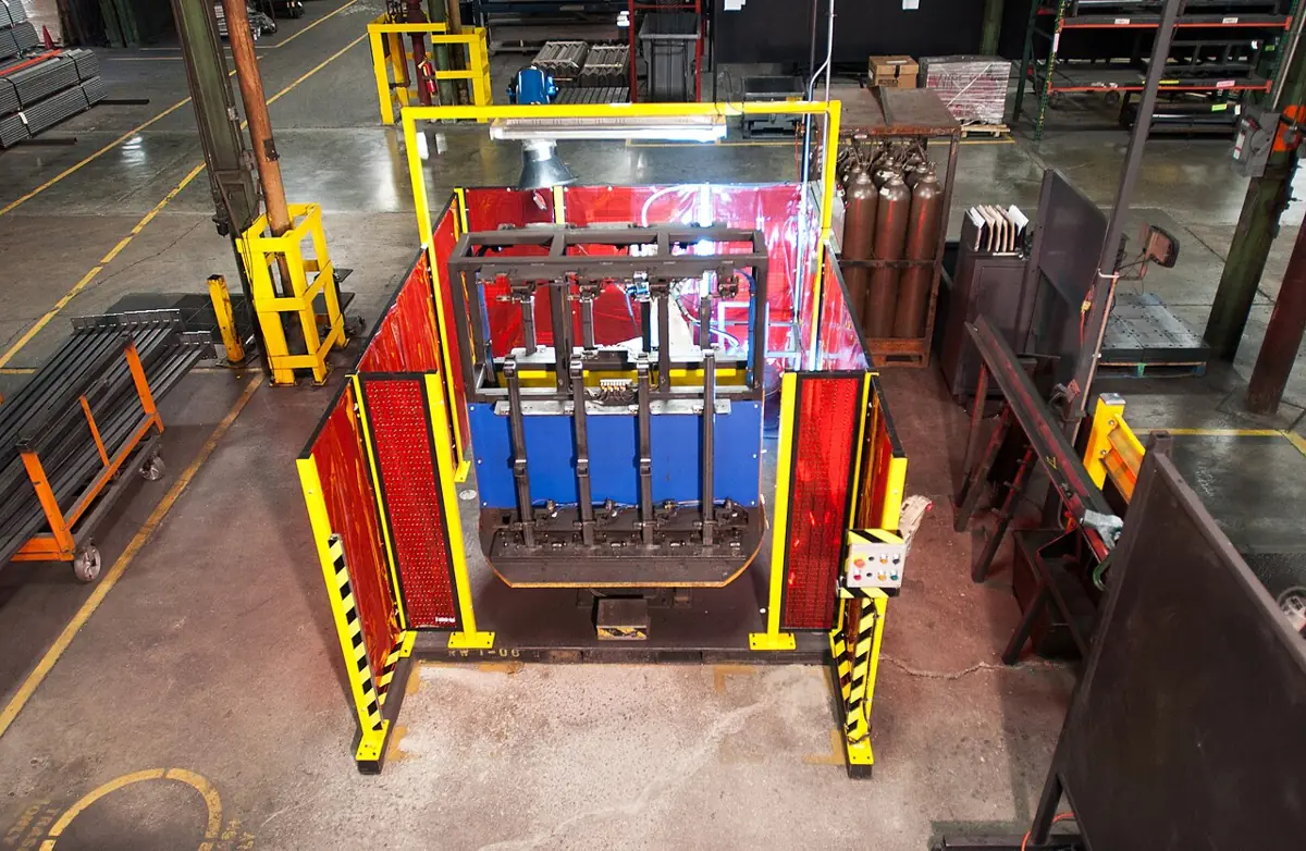
- Robot work cells: a welding or packing cell is planned as a world: robot base, fixtures, guards and conveyors each get a pose in one cell frame, so off-line programs line up with the real cell.
- Mobile robots: ROS REP 105 uses
map,odomandbase_linkframes.odomis smooth but drifts;mapdoes not drift but can jump when localisation corrects it. - Vision-guided picking: a camera finds a part in its optical frame; the calibrated camera pose turns that into the robot base frame before the arm moves (Stage 11).
- Simulators: Gazebo worlds give every model, light and frame a pose relative to the world or another frame, exactly like
desk_world.sdf.
Think
Think about it
Think
Your friend imports a robot model from a game engine into a robotics simulator. The arm appears mirrored: its left side is on the right. The link lengths are all correct. What happened?
Experiment
Try it in the lab
About 55 minutes. The Python part needs only Python 3. The bench part needs an Arduino UNO, an HC-SR04 sensor, a 10 kΩ pot and a box.
Experiment
One object, many frames
You will need
- `desk_world.sdf` and `world_frames.py` (Python 3, no libraries)
- Simulation world explorer (in your browser)
- Arduino UNO, HC-SR04 ultrasonic module, 10 kΩ potentiometer, jumper wires
- Measuring tape, masking tape to mark the table frame, a small cardboard box
Steps
- Run `world_frames.py`. Check the cup’s world position by adding the table pose and the cup pose by hand.
- Move the cup in the SDF to `0.15 0.10 0.05` (relative to the table). Predict the arm-frame numbers, then run and compare.
- Turn `arm_base` to yaw 0. What happens to the cup’s x and y in the arm frame?
- Raise the camera to 1.05 m above the table. Which number in the optical frame changes?
- In the world explorer, view the same object from the world, the table and the camera frames.
- Bench: mark the table frame with tape (origin, +x, +y). Place the sensor at (−0.30, 0), find a box at two places, and compare Serial numbers with the tape measure.
Interactive · Simulation world explorer · Educational
Origin of the scene. Everything else is relative to this frame.
Selected
world
Frame idea
origin
Physics
off (Part 1)
Browser educational world — not Gazebo/Ignition, not Isaac Sim, not MuJoCo, not real-time contacts.
The object never moved, yet its numbers changed with every frame. When the transforms are right, all frames agree on where the object really is — and the ruler agrees too.
Knowledge check
Check your understanding
Knowledge check
1. In ROS’s REP 103, the axes of a body frame are…
2. A camera `_optical` frame uses…
3. In SDF, a `<pose>` without `relative_to` is measured from…
4. What does `<real_time_factor>1.0</real_time_factor>` ask for?
5. Why did the gripper go up when Arjun sent the camera’s z = 0.80?
6. Two transforms A and B: is A × B always equal to B × A?
7. The HC-SR04 reports d = 0.35 m with pan 0°, mounted at table (−0.30, 0). Where is the object in the table frame?
Mini assignment
Hands-on assignment
Mini assignment
A world file of your own desk
Describe your real desk as a simulation world, and prove the frames are right with a ruler and the ultrasonic radar.
Deliverables
- Your `my_desk.sdf`: ground, table, arm mount frame, camera frame and two objects, with measured poses (metres, radians).
- A hand-drawn frame tree (who is the parent of whom) and the output of `world_frames.py` on your file.
- A table comparing, for two objects, the script’s arm-frame position and your tape-measure position.
- Bench: Serial lines from `sonar_frames.ino` for the same two objects, with the error in cm.
Do this, step by step
- Measure the table, arm mount, camera and two objects with a tape, in metres.
- Write
my_desk.sdfusingdesk_world.sdfas the pattern. - Draw the frame tree by hand (who is the parent of whom).
- Run
world_frames.pyon your file and copy the arm-frame positions of the two objects. - Bench: measure the same two objects with
sonar_frames.inoand write the error in cm.
Stuck? Hints, one at a time
- Every pose is relative to its parent. If a number looks doubled, you may have added the table height twice.
- Angles in SDF are radians and follow roll, pitch, yaw. Try one rotation at a time.
- The HC-SR04 measures to the nearest surface in its cone, so aim at a flat side of the object.
Challenges (pick by level)
- 🟢 Beginner: Draw your classroom from above with a world frame in one corner. Write the (x, y) of 5 objects, then re-write them from a frame at the door.
- 🟡 Intermediate: Add a
tool_tipframe to the SDF and make the script print the vector from tool tip to cup. - 🟠 Advanced: Extend
world_frames.pyto print the full roll/pitch/yaw of the camera in the world, and check it by hand. - 🔴 Expert: Make the radar sweep: record (pan, d) for a full turn, convert to table points and save a CSV. Plot it and find the edges of the box.
- ⚫ Research: Read REP 103 and REP 105. Write half a page on why
odommay drift but must be continuous, whilemapmay jump.
Next step
You can build a world and place things in it. In Lesson 6 — Physics Simulation you will switch on time and physics: how a simulator steps the world forward, and why the step size and real-time factor matter.
Look back: Lesson 4: Links, Joints & Robot Structure. Next: Lesson 6: Physics Simulation. Related: Stage 11 — Computer Vision.
Sources
- ROS REP 103 — Standard Units of Measure and Coordinate Conventions — SI units (metres, radians), right-handed frames, body axes x forward / y left / z up,
_opticalcamera frames z forward / x right / y down. - ROS REP 105 — Coordinate Frames for Mobile Platforms —
map,odom,base_link; frames form a tree with one parent each; odom continuous but drifting, map can jump. - Gazebo docs (Harmonic) — SDF worlds — world, physics (
max_step_size,real_time_factor), lights, poses relative to the world, including models. - Gazebo docs (Harmonic) — Building your own robot —
<pose relative_to>, ground plane, box geometry sizes in metres. - Wikipedia — Speed of sound — about 343 m/s in air at 20 °C (used in the HC-SR04 distance formula).
- Photos: Wikimedia Commons (credits under each image). The handedness and roll/pitch/yaw images are shown as diagrams.
Self-attested for now — keep artifacts in your lab notebook.
Complete
Today's goal
0 of 1 done today
Mark this lesson complete when you have worked the experiment, knowledge check, and assignment (even roughly).