
Robotics Orientation · Lesson 02
Anatomy of a Robot
Est. 35–45 min
Why
Why learn robot “body parts”?
When you order parts, wire servos or ask for help on a forum, everyone uses the same words: base, link, joint, DOF, end-effector, frame. Mixing them up leads to wrong wiring, wrong code and wrong maths later (especially in Stage 8, kinematics).
Concept
The big idea: links, joints and degrees of freedom
The parts of a robot body
- Base: the part fixed to the table or floor (or the chassis of a mobile robot). Everything is measured from here. Think of it as the robot’s “main gate” reference point.
- Link: a rigid piece between two joints, like your upper arm or forearm. Links don’t bend; joints do.
- Joint: where two links meet and move relative to each other. The two common types are below.
- Degrees of freedom (DOF): the number of independent ways the robot can move. Usually one per motorised joint.
- End-effector: the business end that touches the task: a gripper, suction cup, pen holder, welding torch or camera.
- Workspace: all the places the end-effector can reach. Like the area you can touch while sitting on your chair without getting up.
- Frame: a named coordinate system (an origin plus x, y, z directions) used to describe positions, e.g. “the cup is 20 cm in front of and 5 cm left of the base”.
Two joint types you will meet everywhere
| Joint type | Motion | Everyday example | Robot example |
|---|---|---|---|
| Revolute (R) | Rotates around an axis (angle, in degrees) | Door hinge, ceiling-fan blades, your elbow | Every joint of the Stage 6 arm |
| Prismatic (P) | Slides along a line (distance, in mm) | Drawer, lift (elevator), syringe | 3D-printer axis, linear actuator |
Why do serious arms have 6 DOF? To place a tool anywhere in 3D space you need 3 numbers for position (x, y, z) and 3 for orientation (roll, pitch, yaw: which way the tool points and how it is twisted). 3 + 3 = 6. With fewer joints, some positions or angles are simply impossible.
How it works
How it actually works: following the chain

Start at the base
The base frame is the reference. Its origin is usually at the centre of the first joint, on the table.
Each joint adds one motion
Joint 1 (waist) turns the whole arm left/right. Joint 2 (shoulder) lifts it. Joint 3 (elbow) folds it. Joints 4–6 (wrist) point and twist the tool.
Motion stacks up
Moving the shoulder carries the elbow, wrist and gripper with it. That is why a 1° error at the shoulder makes a much bigger error at the tip than 1° at the wrist.
Count the DOF
Count the motorised joints that move independently. A gripper that only opens/closes is usually counted separately (“5DOF arm + gripper”).
Find the workspace
Fully stretched, the reach is the sum of the link lengths. Fully folded, it’s the difference. The tip can be anywhere in the ring between them (if joint limits allow).
Visual
Visualise it: build a chain and move the joints
Add revolute or prismatic joints (up to 5), then drag each slider. Watch how moving an early joint swings everything after it, and how DOF changes as you add joints.
Interactive · DOF & joint explorer

Degrees of freedom
2
For a serial chain of 1-DOF joints, DOF ≈ joint count (planar teaching model).
Worked example
Worked example: where is the tip?
Take a flat (2D) arm with two links: L1 = 10 cm (shoulder to elbow) and L2 = 8 cm (elbow to tip). Shoulder angle θ1 is measured from the table; elbow angle θ2 is measured relative to the first link.
x = L1·cos(θ1) + L2·cos(θ1 + θ2) y = L1·sin(θ1) + L2·sin(θ1 + θ2)
- x, y = tip position in cm, measured from the shoulder
- θ1, θ2 = joint angles (convert degrees to radians in code!)
This calculation is called forward kinematics: from joint angles to tip position. In Stage 8 you will also do the reverse (inverse kinematics): from where you want the tip to be, back to the joint angles.
Code lab
Code lab: compute the tip position in Python
Save as two_link_fk.py and run python3 two_link_fk.py. Compare the 30°/60° line with the hand calculation above.
# two_link_fk.py — where is the tip of a 2-link arm? (forward kinematics)
import math

L1 = 10.0  # shoulder -> elbow, cm
L2 = 8.0   # elbow -> tip, cm

def tip(theta1_deg, theta2_deg):
    t1 = math.radians(theta1_deg)
    t2 = math.radians(theta2_deg)
    x = L1 * math.cos(t1) + L2 * math.cos(t1 + t2)
    y = L1 * math.sin(t1) + L2 * math.sin(t1 + t2)
    return x, y

for a, b in [(0, 0), (90, 0), (30, 60), (45, -45), (0, 180)]:
    x, y = tip(a, b)
    print(f"shoulder={a:4d}°  elbow={b:4d}°  ->  tip x={x:6.2f} cm  y={y:6.2f} cm")

print(f"max reach = L1 + L2 = {L1 + L2:.0f} cm, min reach = |L1 - L2| = {abs(L1 - L2):.0f} cm")
Expected output
shoulder=   0°  elbow=   0°  ->  tip x= 18.00 cm  y=  0.00 cm
shoulder=  90°  elbow=   0°  ->  tip x=  0.00 cm  y= 18.00 cm
shoulder=  30°  elbow=  60°  ->  tip x=  8.66 cm  y= 13.00 cm
shoulder=  45°  elbow= -45°  ->  tip x= 15.07 cm  y=  7.07 cm
shoulder=   0°  elbow= 180°  ->  tip x=  2.00 cm  y=  0.00 cm
max reach = L1 + L2 = 18 cm, min reach = |L1 - L2| = 2 cm
Real world
Real robot arms, up close
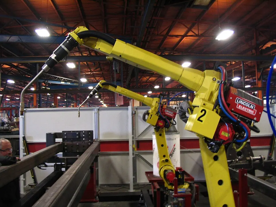
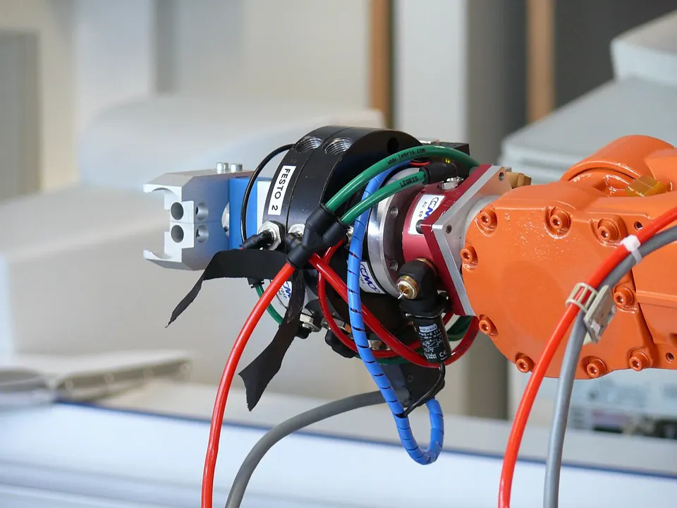
Compare with the Stage 6 desktop arm: fixed base → waist, shoulder, elbow, wrist pitch, wrist roll → gripper. Same anatomy, just smaller, lighter and powered by hobby servos instead of industrial motors.
Mistakes
Common mistakes and debugging
Hardware & safety
Hardware lab and safety notes
Make a 1-joint “arm” you can measure: an ice-cream stick or ruler pinned at one end with a drawing pin to cardboard, and a protractor under it. Mark the tip position at 0°, 30°, 60° and 90° and compare with two_link_fk.py.
- Base = the cardboard; joint = the pin; link = the stick; end-effector = a pen tip taped at the end.
- Add a second stick pinned at the end of the first to get 2 DOF — now you can reach points the first stick alone cannot.
Debugging
Debugging: when it doesn’t work
| Symptom | Likely cause | Fix |
|---|---|---|
| Python tip is far from your drawing | Angles typed in degrees but used as radians | Use math.radians() before cos/sin |
| Elbow angle looks wrong | θ2 measured from the table instead of from link 1 | θ2 is relative to the first link: use t1 + t2 for link 2 |
| Arm cannot reach a point | Point farther than L1 + L2 | Check reach: distance ≤ L1 + L2 |
| Counting too many DOF | Counting fixed screws or the gripper as joints | Count only independent motions |
Think
Think about it
Think
If an arm has 6 revolute joints but one servo is unpowered, how many controllable DOF remain?
Experiment
Try it in the lab: your own arm is a robot arm
Use your own body first, then paper, then the explorer above.
Experiment
Paper DOF sketch
You will need
- Notebook, pencil, ruler
- Your own arm
- Optional: a protractor
Steps
- Sketch a 3-joint planar arm (shoulder, elbow, wrist) and label base, links, joints, end-effector.
- Mark one frame at the base and one at the tool tip.
- Circle which joints change tip position vs tip orientation most strongly (intuition only).
- Body test: put your elbow on the table (that is now your “base”). Keep your wrist straight and only bend the elbow. Your fingertip draws an arc. That’s 1 DOF. Now also bend the wrist: 2 DOF. Notice how many more points you can touch.
- In the explorer above, make a 3-joint arm and try to place the tip at the same spot with two different elbow angles (“elbow up” and “elbow down”).
Knowledge check
Check your understanding
Knowledge check
1. In a serial arm, a “link” is…
2. DOF usually counts…
3. An end-effector is…
4. A drawer sliding in and out is an example of which joint type?
5. Two-link arm with L1 = 10 cm and L2 = 8 cm. What is the maximum reach?
Practice quiz
Mini assignment
Hands-on assignment
Mini assignment
Label a robot photo
Find or sketch any robot (arm, mobile, or toy). Label base, at least two links/joints, end-effector, and one sensor.
Deliverables
- Labeled image or sketch
- One sentence on its DOF estimate
Stretch (code): extend two_link_fk.py to a 3-link arm by adding L3 and theta3. Hint: the third term uses t1 + t2 + t3. Print the tip for (30°, 30°, 30°) with L3 = 5 cm.
Do this, step by step
- Build the 2-stick cardboard arm (L1 = 10 cm, L2 = 8 cm, or the lengths you have).
- Set shoulder 30°, elbow 45°. Measure the tip x and y with a ruler.
- Change
L1,L2and the angles intwo_link_fk.pyto match and run it. - Write the measured and computed tip side by side and the difference in mm.
- Label a robot photo: base, two links, two joints, end-effector, one sensor, and its DOF.
Stuck? Hints, one at a time
- Hint 1: Put the origin (0, 0) exactly at the base pin and draw the x-axis along the table edge.
- Hint 2: Link 2’s direction is θ1 + θ2 from the x-axis, not θ2.
- Hint 3: A difference of a few mm is normal — your pin hole has play (this is called backlash, Lesson 9).
Challenges (pick by level)
- 🟢 Easy: Count the DOF of your own arm from shoulder to wrist (ignore fingers).
- 🟡 Medium: Extend
two_link_fk.pyto 3 links and print the tip for (30°, 30°, 30°) with L3 = 5 cm. - 🟠 Hard: Find two different (θ1, θ2) pairs that put the tip at the same point — this is the “elbow up / elbow down” idea from Stage 8.
Next step
Next, Lesson 3: Sensors — how a robot measures its joints and the world. Related: forward kinematics is done properly in Stage 8 — Kinematics & IK and the maths in Stage 1 — Math for Robotics.
Sources
- Wikipedia — Degrees of freedom (mechanics)) — what counts as a DOF.
- Wikipedia — Robotic arm — joints, links and arm types.
- Wikipedia — Robot end effector — grippers and tools.
- Wikipedia — Forward kinematics — computing tip position from joint angles.
- Photos: Wikimedia Commons (credits under each image).
Self-attested for now — keep artifacts in your lab notebook.
Complete
Today's goal
0 of 1 done today
Mark this lesson complete when you have worked the experiment, knowledge check, and assignment (even roughly).