
Robotics Orientation · Lesson 09
Simulation vs Reality
Est. 35–45 min
Why
Why simulation is useful, and where it lies
Simulation lets you test ideas fast, for free, without breaking gears. But it lies in specific, predictable ways. Knowing exactly how it lies keeps you safe and saves days of confusion when the real robot “doesn’t do what the sim did”.
Concept
The big idea: a simulator is a model, not the world
A simulator uses maths to predict what a robot would do: how joints move, how objects fall, what a camera would see. A digital twin is a simulation set up to match one specific real robot as closely as possible. Both are only as honest as the numbers you give them.
What simulation is great at
- Fast iteration: try 100 versions of a motion plan in minutes.
- Repeatable scenes: the same test, exactly the same way, every time, which is perfect for comparing ideas.
- Safe failure: a simulated arm can crash into the table with no damage and no injury.
- No hardware needed: you can learn planning and ROS 2 before you own a robot.
Where simulation usually differs from reality
| Gap | What happens on the real robot | How to handle it |
|---|---|---|
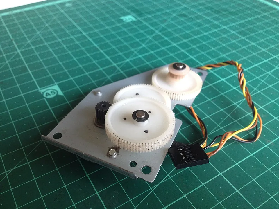
| Backlash (gear slack) | The output shaft can wobble a little without the motor moving | Approach targets from the same direction; better gears |
| Deadband | A servo stops “close enough” to the target, not exactly on it | Measure it; don’t expect sub-degree accuracy from hobby servos |
| Sensor noise | Readings jitter around the true value | Average several readings; filter (later stages) |
| Latency | Data arrives late, so the robot reacts to the past | Move slower; account for delay (Lesson 7) |
| Friction and flex | Joints stick, links bend under load | Measure; re-tune gains on hardware |
| Battery sag | Voltage drops under load, so motors weaken or the board resets | Proper power budget (Lesson 6) |
| Cables and clutter | Wires snag; objects aren’t where the model says | Cable management; check the workspace |
How it works
The sim-to-real workflow, step by step
Build the model
Describe the robot: link lengths, joint limits, masses. (Stage 19 covers URDF, the standard robot description format.)
Test in simulation
Run the motion or controller. Fix the obvious bugs here, cheaply.
Measure the real robot
Use a ruler, protractor and logs: actual link lengths, actual joint range, actual servo error. Engineers call this system identification.
Update the model
Put the measured numbers back into the simulation so it matches your robot, not a default one.
Try on hardware, gently
Low speed, reduced range, hand near the power switch. Compare the logs with the sim.
Repeat
Every difference you find either improves the model or tells you to change the hardware.
Visual
Visualise it: the same command in two worlds
Toy servo model: change backlash, deadband, noise and latency and watch the real final angle drift away from the perfect simulated one.
Interactive · Simulation vs reality (toy servo)
Sim final angle
90.0°
Real final angle
88.5°
Static error
-1.5°
Stale reading while moving
6.0°
5 sensor readings: 89.0, 88.2, 88.1, 88.2, 88.9
This is a teaching model with made-up but realistic-looking knobs, not a model of any specific servo. The point: each small imperfection is ignored by a perfect simulator, and they add up on real hardware.
Worked example
Worked example: where does the servo really stop?
You command a joint to 90°. In the simulator it lands on exactly 90.0°. On the real arm, assume (as in the visualisation’s defaults) 2° of gear backlash and a 1° servo deadband, approaching from below.
Small numbers, but on a 30 cm arm, 1.5° of joint error moves the gripper tip about 30 × 0.026 ≈ 0.8 cm. That’s enough to miss a small object.
Code lab
Code lab: the same command in two worlds
Save as sim_vs_real.py. The fixed random seed makes your output match ours exactly. Change BACKLASH, DEADBAND and NOISE and re-run.
# sim_vs_real.py — same command, two worlds.
import random

random.seed(42)  # fixed seed so your output matches ours

TARGET = 90.0
BACKLASH = 2.0   # degrees of gear slack
DEADBAND = 1.0   # servo stops when within ±0.5°
NOISE = 0.5      # ± degrees on each sensor reading

sim_final = TARGET
real_final = TARGET - DEADBAND / 2 - BACKLASH / 2   # approaching from below

print(f"sim  final angle : {sim_final:.1f}°")
print(f"real final angle : {real_final:.1f}°  (error {real_final - TARGET:+.1f}°)")
readings = [real_final + random.uniform(-NOISE, NOISE) for _ in range(5)]
print("real sensor reads:", ", ".join(f"{r:.2f}" for r in readings))
print(f"average reading  : {sum(readings) / len(readings):.2f}°")
Expected output
sim  final angle : 90.0°
real final angle : 88.5°  (error -1.5°)
real sensor reads: 88.64, 88.03, 88.28, 88.22, 88.74
average reading  : 88.38°
Real world
Simulation in real robotics work
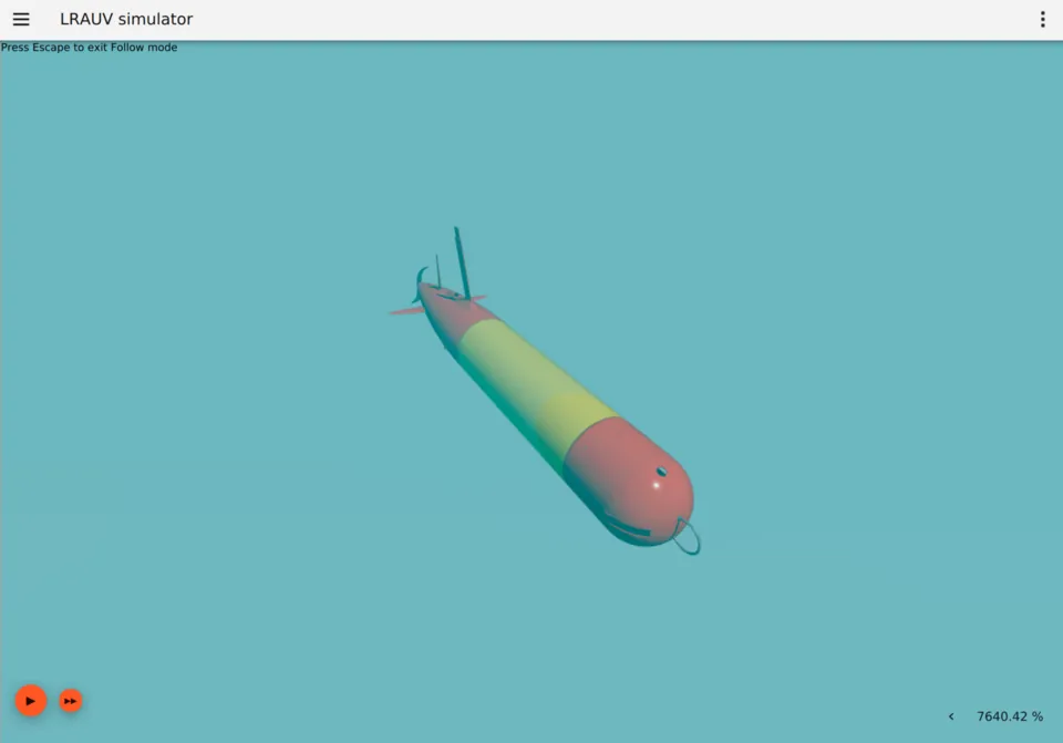
Industry uses digital twins to plan factory cells and test robot programs before touching the line. Research labs train robot skills in simulation and then carefully transfer them to hardware. In this roadmap, Stage 12 (Robot Simulation & Digital Twin) teaches simulation properly, and the NVIDIA Isaac stage is planned for later. Stage 6 teaches hardware truth first, so you recognise when a sim is “too clean”.
Mistakes
Common mistakes and confusions
Hardware & safety
Hardware lab and safety notes
See the sim-to-real gap with one servo: command it to 90° approaching from 45° and from 135°, and mark where the horn really stops each time.
- Servo wired as in Lesson 4: signal pin 9, power from a separate 5–6 V supply, common ground.
- Tape a long paper pointer on the horn and a protractor behind it.
- Repeat 5 times from each side and write the angles.
Debugging
Debugging: when it doesn’t work
| Symptom | Likely cause | Fix |
|---|---|---|
| Real robot overshoots where sim did not | Sim has no backlash/delay or wrong mass | Add delay, backlash and noise to the sim |
| Two approaches stop at different angles | Backlash / dead band in the gears | Always approach from the same side |
| Sim works, real one browns out | Sim ignores supply limits | Check current budget (Lesson 6) |
| Results differ every run | Real noise and friction | Run 5+ trials and use the average |
Think
Think about it
Think
Name two things a perfect-looking sim demo can hide that will appear on a desk arm.
Experiment
Try it in the lab: build your gap list
Use the visualisation above to feel how each gap changes the result, then write your list.
Experiment
Gap list
You will need
- The simulation-vs-reality visualisation
- Notebook
Steps
- Write five sim-to-real gaps relevant to a hobby arm.
- Mark which ones you can mitigate with measurement vs better mechanical design.
- In the visualisation, set backlash and deadband to 0 and noise to ±0. Does the real angle now match the sim? Then raise only the latency and joint speed. Which readout changes?
Knowledge check
Check your understanding
Knowledge check
1. Simulation is most valuable when you…
2. A common sim-to-real gap is…
3. You should treat default model parameters as…
4. Averaging many sensor readings mainly helps against…
5. With 2° backlash and 1° deadband, a joint commanded to 90° from below stops near…
Practice quiz
Mini assignment
Hands-on assignment
Mini assignment
Validation plan
Write a mini plan: three checks you will run on real hardware after any sim-based motion idea (limits, speed, E-stop / power kill).
Deliverables
- Three validation checks
Stretch (code): modify sim_vs_real.py to approach the target from above as well, and print the difference between the two final angles. Then work out which setting you would change first to shrink it.
Do this, step by step
- Run
sim_vs_real.pyand note the sim final angle, the real final angle and the average sensor reading. - Do the hardware test above and write the 10 measured angles in a table.
- Write your validation plan: three checks (limits, speed, power kill) you will always do on real hardware after a sim idea.
Stuck? Hints, one at a time
- Hint 1: Find the spread: largest minus smallest measured angle from each side.
- Hint 2: If the two sides differ by a few degrees, that is backlash — your sim did not have it.
- Hint 3: A good check is measurable: “joint stays between 10° and 170°”, not “arm looks OK”.
Challenges (pick by level)
- 🟢 Easy: Change
NOISEfrom 0.5 to 2.0 insim_vs_real.py. How much does the average reading move? - 🟡 Medium: Approach the target from above too and print the difference between the two final angles.
- 🟠 Hard: Change
BACKLASHandDEADBANDuntil the “real” final angle matches what you measured on your servo.
Next step
Next, Lesson 10: Your Robotics Journey. Related: full simulators and digital twins in Stage 12 — Simulation & Digital Twin.
Sources
- Wikipedia — Robotics simulator — what simulators model.
- Gazebo documentation — open-source robot simulator.
- MuJoCo overview — physics engine used in robotics research.
- Wikipedia — Backlash (engineering)) — play in gears.
- Tobin et al. (2017) — Domain randomization — training in sim with randomised visuals so it transfers to real.
- Photos: Wikimedia Commons (credits under each image).
Self-attested for now — keep artifacts in your lab notebook.
Complete
Today's goal
0 of 1 done today
Mark this lesson complete when you have worked the experiment, knowledge check, and assignment (even roughly).