
Robotics Orientation · Lesson 05
The Robot Brain
Est. 40–55 min
Why
Why the “brain” choice matters
People say “robot brain”, but in the lab you choose a controller based on very practical questions: How many pins do I need? How fast and how regularly must my loop run? Do I need a camera, Wi-Fi or Linux? Choosing wrong means jittery servos, missed sensor readings, or a board that simply can’t run your software.
Concept
The big idea: microcontrollers vs single-board computers
Two kinds of brains
| Microcontroller (MCU) | Single-board computer (SBC) | |
|---|---|---|
| Example | Arduino Uno (ATmega328P chip) | Raspberry Pi 4 |
| Speed and memory | 16 MHz, 32 KB program flash, 2 KB RAM | Quad-core 64-bit ARM processor, gigabytes of RAM |
| Operating system | None: your program is the only thing running | Linux (many programs share the CPU) |
| Superpower | Precise, predictable timing; direct pin control (PWM, ADC); starts instantly | Cameras, Wi-Fi, Python libraries, ROS 2, AI models |
| Weakness | Too small for cameras, maps or AI | Timing can jitter because Linux may pause your program |
| Human analogy | Spinal reflexes (pull your hand off a hot tawa) | Thinking brain (planning what to cook) |
Real-time does not mean “very fast”. It means on time, every time. A loop that runs exactly every 20 ms is real-time; one that is usually 5 ms but sometimes 200 ms is not, even though it is faster on average.
Firmware vs software
- Firmware runs on the microcontroller and talks directly to pins, timers and hardware buses. Your Arduino sketch is firmware.
- High-level software runs on a computer or SBC and works with files, networks, cameras and messages. Your Python scripts and (later) ROS 2 nodes.
- A common robot design uses both: the SBC decides “move the elbow to 60°”, then sends that over a USB cable to the MCU, which generates the exact servo pulses.
How it works
How an Arduino actually runs your code
Power on / reset
A small built-in program (the bootloader) checks whether new code is arriving over USB, then jumps to your sketch.
setup() runs once
Set pin modes, start Serial, attach servos.
loop() runs forever
As soon as loop() ends, it starts again. Each pass is one heartbeat: read sensors → decide → write outputs.
Time is a budget
If you want 50 updates per second, each loop gets 1000 ÷ 50 = 20 ms. Every sensor read, calculation, print and
delay()spends part of that budget.millis() is the clock
millis()returns milliseconds since power-on. Comparing it with a saved time lets you do things “every 1000 ms” without stopping the loop. That’s the non-blocking style used by every serious robot sketch.
Visual
Visualise it: does your loop finish on time?
Set a target loop rate, then add sensor time, compute time, serial printing and delay(). See how much of the time budget each task uses and what rate you really get.
Interactive · Loop timing budget
Wanted rate
50 Hz
Time used / loop
35.25 ms
CPU budget used
176 %
Actual rate
28.4 Hz
Serial time here = characters × 10 bits ÷ baud. On an Arduino Uno, Serial.print() returns at once while its small transmit buffer (64 bytes) has room; when you print more than the line can carry, print() waits — so in steady state each loop pays roughly this time.
Worked example
Worked example: the 20 ms budget
You want your arm controller to update 50 times per second (50 Hz). The budget per loop is 20 ms. Let’s spend it:
| Task | Time | How we know |
|---|---|---|
| Read a sensor | 3 ms | Example value; measure your own with micros() |
| Compute the next servo angles | 1 ms | Example value |
| Print 30 characters at 9600 baud | 31.25 ms | 30 chars × 10 bits ÷ 9600 bits/s |
| Total | 35.25 ms | Over budget: the loop only manages ≈ 28 Hz |
Try exactly these numbers in the visualisation above: 50 Hz, sensor 3 ms, compute 1 ms, 30 characters, then toggle 9600 ↔ 115200 baud.
Code lab
Code lab: the frozen robot vs the responsive robot
Both sketches blink the built-in LED once a second and watch a push button on pin 2 (button between pin 2 and GND). Upload the first one and press the button quickly. Most presses are missed.
// blink_delay.ino — the "frozen robot" version. Don't build robots like this!
const int LED = LED_BUILTIN;
const int BUTTON = 2;   // push button to GND (uses the internal pull-up)

void setup() {
  pinMode(LED, OUTPUT);
  pinMode(BUTTON, INPUT_PULLUP);
  Serial.begin(9600);
}

void loop() {
  digitalWrite(LED, HIGH);
  delay(1000);                       // CPU does NOTHING else for 1 second
  digitalWrite(LED, LOW);
  delay(1000);                       // ...and again
  if (digitalRead(BUTTON) == LOW) {  // checked only once every 2 seconds!
    Serial.println("Button pressed (noticed late)");
  }
}
What you will see
Button pressed (noticed late)
(only if you happen to be holding the button at the moment it is checked, once every 2 seconds)
Now the non-blocking version. It does three jobs “at the same time” by never waiting:
// blink_millis.ino — non-blocking loop: blink AND watch the button at the same time.
const int LED = LED_BUILTIN;
const int BUTTON = 2;              // push button to GND (uses the internal pull-up)
const unsigned long BLINK_MS = 1000;

unsigned long lastBlink = 0;
bool ledOn = false;
bool lastButton = HIGH;
unsigned long loops = 0;
unsigned long lastReport = 0;

void setup() {
  pinMode(LED, OUTPUT);
  pinMode(BUTTON, INPUT_PULLUP);
  Serial.begin(9600);
}

void loop() {
  unsigned long now = millis();

  // Task 1: blink without blocking
  if (now - lastBlink >= BLINK_MS) {
    lastBlink = now;
    ledOn = !ledOn;
    digitalWrite(LED, ledOn ? HIGH : LOW);
  }

  // Task 2: react to the button within microseconds
  bool b = digitalRead(BUTTON);
  if (b == LOW && lastButton == HIGH) {
    Serial.println("Button pressed (noticed immediately)");
  }
  lastButton = b;

  // Task 3: once a second, report how many times loop() ran
  loops++;
  if (now - lastReport >= 1000) {
    lastReport = now;
    Serial.print("loop() ran ");
    Serial.print(loops);
    Serial.println(" times in the last second");
    loops = 0;
  }
}
What you will see (the loop count is in the thousands per second; the exact number depends on your board)
loop() ran … times in the last second
Button pressed (noticed immediately)
loop() ran … times in the last second
Real world
Real robot brains
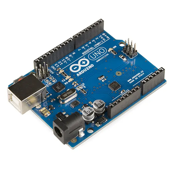
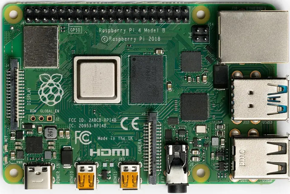
- Stage 6 arm: Arduino generates the servo pulses; your laptop can optionally send target angles over USB serial.
- ROS 2 robots (Stage 10): a Linux computer runs navigation and vision; a microcontroller handles motors and encoders.
- Hobby drones: a dedicated flight-controller MCU runs the fast stabilisation loop; a companion computer may handle the camera.
Mistakes
Common mistakes and debugging
Hardware & safety
Hardware lab and safety notes
Prove the difference between delay() and millis() on a real Uno.
- Push button between pin 2 and GND (sketch uses
INPUT_PULLUP). - Built-in LED on pin 13 — no extra wiring.
- Upload
blink_delay.ino, press the button quickly many times, then uploadblink_millis.inoand repeat.
Debugging
Debugging: when it doesn’t work
| Symptom | Likely cause | Fix |
|---|---|---|
| Button presses are missed | Code is stuck inside delay() | Use the millis() pattern |
| One press prints 2–3 times | Switch bounce | Ignore changes for ~20 ms after a press (debounce) |
| Blink timing goes wrong after a long time | Using int for times | Store times in unsigned long and use now - last >= interval |
| Serial Monitor shows nothing | Wrong baud or wrong port | Set 9600 baud; pick the right port in Tools → Port |
Think
Think about it
Think
You want 30 Hz vision and 200 Hz joint PWM. One Raspberry Pi alone — good idea?
Experiment
Try it in the lab: pick the brain for the job
Experiment
Controller choice card
You will need
- Notebook
- The loop-timing visualisation above
- Optional: Arduino Uno, push button, USB cable
Steps
- For a line follower, a camera arm, and a ROS 2 demo, pick MCU / SBC / both.
- Write the one responsibility you would NOT put on the SBC alone.
- In the loop-timing lab, set 100 Hz, sensor 3 ms, compute 1 ms, 20 characters at 9600 baud. Is it on time? Now fix it two different ways.
- With hardware: upload both blink sketches and count how many of 10 quick button presses each one notices.
Knowledge check
Check your understanding
Knowledge check
1. A common robust pattern is…
2. MCU strengths for hobby robots include…
3. Firmware primarily…
4. How long does it take to send 30 characters at 9600 baud (10 bits per character)?
5. “Real-time” in robotics mainly means…
Practice quiz
Mini assignment
Hands-on assignment
Mini assignment
Interface sketch
Draw boxes: Sensors → MCU → (optional) SBC → Actuators. Label two messages that cross the MCU↔SBC link (e.g. joint targets, telemetry).
Deliverables
- Block diagram
- Two interface notes
Stretch (code): add a fourth task to blink_millis.ino that prints “tick” every 250 ms using its own lastTick variable. All four tasks should run without any delay().
Do this, step by step
- Upload
blink_delay.ino. Press the button 10 times quickly and count how many presses get noticed. - Upload
blink_millis.inoand repeat. Note the “loop() ran … times” number. - Draw the interface sketch: Sensors → MCU → (optional) SBC → Actuators, and label two messages that cross the MCU↔SBC link.
Stuck? Hints, one at a time
- Hint 1: With
delay(1000)the board is blind for a full second, so short presses are lost. - Hint 2: The loop count tells you how many times per second your robot could check its sensors.
- Hint 3: Typical MCU↔SBC messages: joint targets going down, sensor readings / battery voltage coming up.
Challenges (pick by level)
- 🟢 Easy: Change
BLINK_MSto 250 and confirm the button still works. - 🟡 Medium: Add a fourth task that prints “tick” every 250 ms with its own
lastTick, with nodelay(). - 🟠 Hard: Add a 20 ms debounce so each press prints exactly once.
Next step
Next, Lesson 6: Power & Communication. Related: microcontrollers in depth in Stage 4 — Electronics, Linux on an SBC in Stage 3 — Linux & Dev Environment, Python in Stage 2.
Sources
- Arduino — Blink Without Delay — the millis() pattern.
- Arduino — millis() — returns unsigned long, overflows after about 50 days.
- Arduino — Debounce — why one press can read as many.
- Arduino — UNO R3 docs — ATmega328P, 16 MHz, 2 KB SRAM.
- Wikipedia — Microcontroller — MCU vs general computer.
- Photos: Wikimedia Commons (credits under each image).
Self-attested for now — keep artifacts in your lab notebook.
Complete
Today's goal
0 of 1 done today
Mark this lesson complete when you have worked the experiment, knowledge check, and assignment (even roughly).