
Trajectory Planning & Motion Generation · Lesson 10
Orientation Trajectories
Est. 50–70 min
Why
Why this lesson matters
A tool’s pose is its position plus its orientation — which way the gripper, torch, nozzle or camera is pointing. Lesson 9 planned position. This lesson plans orientation: how to turn from one orientation to another by the shortest, smoothest way, and how to keep it in step with position using the same time scaling s(t).
By the end of this lesson you will be able to: explain why lerping Euler (roll-pitch-yaw) angles can take the long way or a curved, uneven way; use the shortest-angle rule for a single heading; use slerp on unit quaternions for 3D orientation; combine it with a quintic s(t); and see the difference with a 2-servo pan-tilt pointer.
Concept
Turning the tool smoothly: slerp, not Euler lerp
Orientation is not three ordinary numbers
Position lives in a flat space: halfway between two points is simply their average. Orientation does not. Angles wrap around (170° and −190° are the same heading), and three Euler angles can describe the same orientation in more than one way. *Modern Robotics* (§9.2.1) therefore plans orientation separately with R(s) = R_start · exp(log(R_startᵀ R_end) · s): rotate about one fixed axis, from start to end, at a rate set by s(t), while the position follows p(s) = p_start + s·(p_end − p_start).
| Method | What it does | Problem |
|---|---|---|
| Lerp a single heading naively | h(s) = h0 + s·(h1 − h0) | Can go the long way round (170° → −170° = 340°) |
| Shortest-angle heading | Wrap the change into −180°…180° first | Fine for one angle (planar wrist, mobile robot heading) |
| Lerp Euler / roll-pitch-yaw angles | Lerp three angles separately | Wrap-around, curved and uneven rotation, trouble near gimbal lock |
| Slerp of unit quaternions | Rotate about one fixed axis at a steady rate | None for our purpose — the standard choice |
What is slerp?
Slerp (spherical linear interpolation) moves between two points on a sphere so that the angle covered grows evenly with s. Applied to unit quaternions it gives a rotation about a fixed axis with uniform angular speed — the “straight line” of orientations. Formula: slerp(q0, q1; s) = [sin((1−s)Ω)·q0 + sin(sΩ)·q1] / sin Ω, where cos Ω = q0·q1. Because q and −q are the same rotation, if the dot product is negative you flip one of them first, so the turn takes the short way.
Gimbal lock in one paragraph
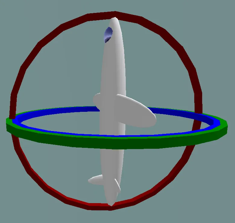
With three nested rotation axes (like Euler angles or a 3-gimbal mount), when two axes line up one degree of freedom is lost — gimbal lock. Near it, a small turn of the tool needs large, fast changes of the angles. Robots call the same thing a wrist flip (wrist singularity). Planning with quaternions avoids the maths trap; the physical wrist singularity still has to be avoided by the path.
Visual
Visualise it: tool heading along a path
Planar stand-in: along a straight tool line, the tool heading θ₁ + θ₂ of a 2R arm changes on its own. To control heading you need another joint — a wrist — and an orientation plan.
Interactive · Cartesian trajectory planner (2R educational · Stage 8 IK)


Interpolate a straight line in task space, then call Stage 8 ik2R each sample. Labeled simplified — not industrial 6DOF.
- EE (x,y)
- 100.0, 40.0
- Joints (°)
- -18.4, 96.4
- Path health (samples)
- unreachable=0 · joint-limit≈0 · singular=0
Code lab
Code lab: Euler lerp vs slerp, in numbers
orientation_paths.py builds quaternions from roll-pitch-yaw angles, measures how much the tool really turns, and compares Euler lerp with slerp in 20 equal steps. Part 2 shows the shortest-angle rule for one heading. Part 3 combines slerp with the quintic timing from Lesson 8. Run python3 orientation_paths.py.
# orientation_paths.py - Stage 9 Lesson 10: orientation trajectories
# Compares "lerp the Euler angles" with quaternion slerp. Pure Python, no libraries.
import math

def quat_from_rpy(roll, pitch, yaw):
    """Roll-pitch-yaw in degrees (R = Rz(yaw) Ry(pitch) Rx(roll)) -> unit quaternion (w, x, y, z)."""
    r, p, y = (math.radians(a) / 2 for a in (roll, pitch, yaw))
    cr, sr, cp, sp, cy, sy = math.cos(r), math.sin(r), math.cos(p), math.sin(p), math.cos(y), math.sin(y)
    return (cr*cp*cy + sr*sp*sy, sr*cp*cy - cr*sp*sy, cr*sp*cy + sr*cp*sy, cr*cp*sy - sr*sp*cy)

def dot(a, b):
    return sum(x*y for x, y in zip(a, b))

def angle_between(q1, q2):
    """Rotation angle (deg) needed to go from q1 to q2 (shortest way)."""
    d = min(1.0, abs(dot(q1, q2)))
    return math.degrees(2 * math.acos(d))

def slerp(q1, q2, s):
    d = dot(q1, q2)
    if d < 0:                       # q and -q are the same rotation: take the short way
        q2, d = tuple(-c for c in q2), -d
    d = min(1.0, d)
    th = math.acos(d)
    if th < 1e-9:
        return q1
    a, b = math.sin((1 - s) * th) / math.sin(th), math.sin(s * th) / math.sin(th)
    return tuple(a*x + b*y for x, y in zip(q1, q2))

def quintic(u):
    return 10*u**3 - 15*u**4 + 6*u**5

def study(label, rpy_a, rpy_b, n=20):
    qa, qb = quat_from_rpy(*rpy_a), quat_from_rpy(*rpy_b)
    print(f"\n{label}: rpy {rpy_a} -> {rpy_b}")
    print(f"  shortest rotation between them: {angle_between(qa, qb):6.1f} deg")
    for name in ("Euler lerp", "slerp"):
        steps, prev = [], qa
        for k in range(1, n + 1):
            s = k / n                          # constant speed in s for this comparison
            if name == "slerp":
                q = slerp(qa, qb, s)
            else:
                q = quat_from_rpy(*[a + s*(b - a) for a, b in zip(rpy_a, rpy_b)])
            steps.append(angle_between(prev, q))
            prev = q
        print(f"  {name:10s}: total turning {sum(steps):6.1f} deg, per-step min {min(steps):5.2f} max {max(steps):5.2f} deg")

print("Part 1 - orientation in 3D: Euler lerp vs slerp (20 equal steps of s)")
study("A) yaw wrap-around", (0, 0, 170), (0, 0, -170))
study("B) tilt then turn", (0, 80, 0), (90, 80, 90))
study("C) two-axis move", (0, 0, 0), (60, 0, 60))

print("\nPart 2 - planar heading: always take the short way")
def wrap180(a):
    return (a + 180) % 360 - 180
for h0, h1 in ((170, -170), (10, 350), (30, 120)):
    print(f"  {h0:5d} -> {h1:5d}: naive change {h1 - h0:6d} deg, shortest change {wrap180(h1 - h0):6.0f} deg")

print("\nPart 3 - slerp + quintic timing: rotate 90 deg about z in T = 2 s")
qa, qb, T = quat_from_rpy(0, 0, 0), quat_from_rpy(0, 0, 90), 2.0
prev = qa
for k in range(0, 11):
    t = T * k / 10
    q = slerp(qa, qb, quintic(t / T))
    rate = angle_between(prev, q) / (T / 10) if k else 0.0
    yaw = math.degrees(2 * math.atan2(q[3], q[0]))
    print(f"  t={t:4.1f}  yaw {yaw:5.1f} deg  rate {rate:5.1f} deg/s")
    prev = q
Output (run with python3 orientation_paths.py)
Part 1 - orientation in 3D: Euler lerp vs slerp (20 equal steps of s)

A) yaw wrap-around: rpy (0, 0, 170) -> (0, 0, -170)
  shortest rotation between them:   20.0 deg
  Euler lerp: total turning  340.0 deg, per-step min 17.00 max 17.00 deg
  slerp     : total turning   20.0 deg, per-step min  1.00 max  1.00 deg

B) tilt then turn: rpy (0, 80, 0) -> (90, 80, 90)
  shortest rotation between them:   14.1 deg
  Euler lerp: total turning   15.7 deg, per-step min  0.78 max  0.78 deg
  slerp     : total turning   14.1 deg, per-step min  0.71 max  0.71 deg

C) two-axis move: rpy (0, 0, 0) -> (60, 0, 60)
  shortest rotation between them:   82.8 deg
  Euler lerp: total turning   84.8 deg, per-step min  4.24 max  4.24 deg
  slerp     : total turning   82.8 deg, per-step min  4.14 max  4.14 deg

Part 2 - planar heading: always take the short way
    170 ->  -170: naive change   -340 deg, shortest change     20 deg
     10 ->   350: naive change    340 deg, shortest change    -20 deg
     30 ->   120: naive change     90 deg, shortest change     90 deg

Part 3 - slerp + quintic timing: rotate 90 deg about z in T = 2 s
  t= 0.0  yaw   0.0 deg  rate   0.0 deg/s
  t= 0.2  yaw   0.8 deg  rate   3.9 deg/s
  t= 0.4  yaw   5.2 deg  rate  22.2 deg/s
  t= 0.6  yaw  14.7 deg  rate  47.3 deg/s
  t= 0.8  yaw  28.6 deg  rate  69.5 deg/s
  t= 1.0  yaw  45.0 deg  rate  82.2 deg/s
  t= 1.2  yaw  61.4 deg  rate  82.2 deg/s
  t= 1.4  yaw  75.3 deg  rate  69.5 deg/s
  t= 1.6  yaw  84.8 deg  rate  47.3 deg/s
  t= 1.8  yaw  89.2 deg  rate  22.2 deg/s
t= 2.0 yaw 90.0 deg rate 3.9 deg/sTry it: on a straight tool line the planar tool heading (θ₁ + θ₂) still changes. A 6DOF arm would use its wrist to plan the heading separately (simplified 2R arm).
Interactive · Cartesian trajectory planner (2R educational · Stage 8 IK)
Interpolate a straight line in task space, then call Stage 8 ik2R each sample. Labeled simplified — not industrial 6DOF.
- EE (x,y)
- 100.0, 40.0
- Joints (°)
- -18.4, 96.4
- Path health (samples)
- unreachable=0 · joint-limit≈0 · singular=0
Real world
Orientation trajectories in the real world
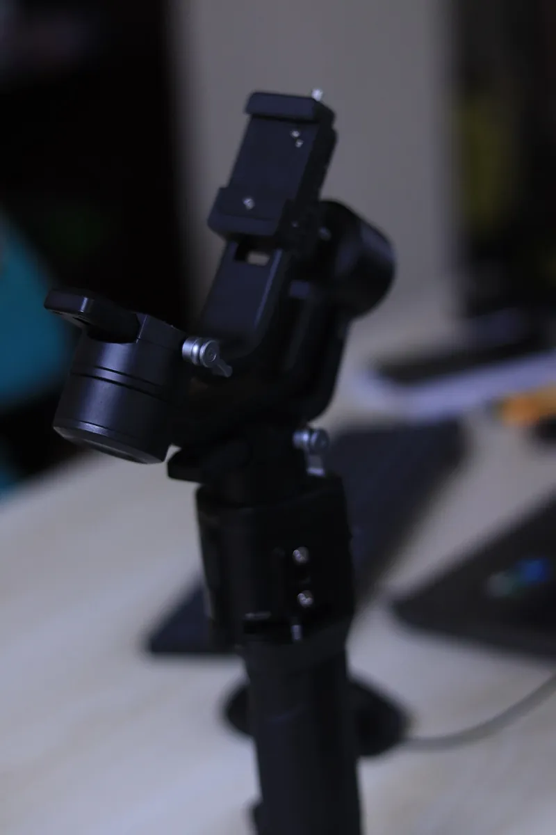
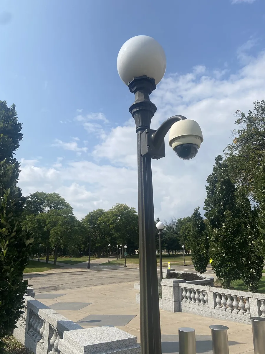
- Camera gimbals and PTZ cameras: smooth pans and tilts between saved shots.
- Welding, gluing and painting robots: the torch or gun must keep a set angle to the seam while it moves along it.
- Animation and games: slerp became popular in computer graphics for animating 3D rotations (Ken Shoemake, 1985).
- Spacecraft and drones: orientation is computed with quaternions to avoid gimbal-lock trouble; Apollo’s gimbal-based guidance platform had to avoid gimbal lock.
Bench build
Bench build: a pan-tilt pointer, two ways
A pan-tilt bracket with two hobby servos is a tiny “wrist”. Tape a drinking straw to it as the pointer. pan_tilt_slerp.ino moves from pose A (pan 20°, tilt 60°) to pose B (pan 160°, tilt 60°). The first round trip lerps the pan and tilt angles: the straw tip sweeps sideways at constant tilt. The next round trip slerps the pointing direction: the straw takes the great-circle route, rising to about 79° tilt in the middle — a turn of only 56° on the sphere. The sketch prints the highest tilt reached.
| From | To | Note |
|---|---|---|
| Pan servo signal | D9 | 0–180° pan |
| Tilt servo signal | D10 | 0 = horizontal, 90 = straight up |
| Both servos + and − | Separate 5–6 V supply, 1 A or more | Never the Arduino 5 V pin |
| Supply − | Arduino GND | Common ground |
| Button | D2 ↔ GND | INPUT_PULLUP |
Mount
Fix the bracket firmly to a board. Check that tilt 0–90° moves the straw from horizontal to straight up; flip the servo horn if it is reversed.
Mark the ceiling
Stick a small paper target above the bracket. Watch where the straw points during each move.
Angle lerp
Press D2 twice (A → B → A). Note the path and the printed highest tilt (60.0).
Slerp
Press D2 twice again. The straw now rises towards the ceiling mid-way; the printed highest tilt is about 79°.
Explore
Change TILT_A and TILT_B to 85. The pointing direction now changes by only about 9°, yet angle lerp still swings the pan servo through 140°. Near “straight up”, pan barely matters — that is gimbal lock in 2 axes.
// pan_tilt_slerp.ino - Stage 9 Lesson 10: two ways to turn a pointer
// A pan-tilt bracket points a drinking straw (the "tool"). Press D2 to move between
// pose A and pose B. Each press alternates the method:
//   mode 0: lerp pan and tilt angles separately ("Euler lerp")
//   mode 1: slerp the pointing direction (shortest turn on the sphere)
// Both use the same quintic timing over T_MOVE seconds. Watch the straw tip path.
// Wiring: pan servo signal D9, tilt servo signal D10.
//         Both servos on a SEPARATE 5-6 V supply (1 A+); supply GND -> Arduino GND. Button D2 -> GND.
#include <Servo.h>

Servo pan, tilt;
const float PAN_A = 20, TILT_A = 60;     // pose A (deg); tilt 0 = horizontal, 90 = straight up
const float PAN_B = 160, TILT_B = 60;    // pose B
const float T_MOVE = 2.5;
const unsigned long DT_MS = 20;
bool atA = true;
int mode = 0;

void writeDeg(Servo &s, float deg) {
  deg = constrain(deg, 0, 180);
  s.writeMicroseconds(544 + (int)(deg * (2400 - 544) / 180.0));
}

float quintic(float u) { return u * u * u * (10 - 15 * u + 6 * u * u); }

void dirFrom(float p, float t, float v[3]) {            // pan/tilt (deg) -> unit vector
  float pr = radians(p), tr = radians(t);
  v[0] = cos(tr) * cos(pr); v[1] = cos(tr) * sin(pr); v[2] = sin(tr);
}

void anglesFrom(const float v[3], float &p, float &t) { // unit vector -> pan/tilt (deg)
  t = degrees(asin(constrain(v[2], -1.0, 1.0)));
  p = degrees(atan2(v[1], v[0]));
}

void slerpDir(const float a[3], const float b[3], float s, float out[3]) {
  float d = constrain(a[0] * b[0] + a[1] * b[1] + a[2] * b[2], -1.0, 1.0);
  float th = acos(d);
  if (th < 1e-4) { for (int i = 0; i < 3; i++) out[i] = a[i]; return; }
  float ka = sin((1 - s) * th) / sin(th), kb = sin(s * th) / sin(th);
  for (int i = 0; i < 3; i++) out[i] = ka * a[i] + kb * b[i];
}

void moveTo(float p0, float t0, float p1, float t1) {
  float a[3], b[3], v[3];
  dirFrom(p0, t0, a); dirFrom(p1, t1, b);
  unsigned long start = millis();
  float maxTilt = -90;
  while (true) {
    float u = (millis() - start) / 1000.0 / T_MOVE;
    if (u > 1) u = 1;
    float s = quintic(u), p, t;
    if (mode == 0) { p = p0 + s * (p1 - p0); t = t0 + s * (t1 - t0); }
    else { slerpDir(a, b, s, v); anglesFrom(v, p, t); }
    if (t > maxTilt) maxTilt = t;
    writeDeg(pan, p); writeDeg(tilt, t);
    if (u >= 1) break;
    delay(DT_MS);
  }
  Serial.print(mode == 0 ? F("angle lerp") : F("direction slerp"));
  Serial.print(F(" - highest tilt on the way: ")); Serial.println(maxTilt, 1);
}

void setup() {
  Serial.begin(115200);
  pinMode(2, INPUT_PULLUP);
  pan.attach(9); tilt.attach(10);
  writeDeg(pan, PAN_A); writeDeg(tilt, TILT_A);   // quick move to A at power-up
  Serial.println(F("Press D2 to move. Modes alternate: angle lerp, direction slerp."));
}

void loop() {
  if (digitalRead(2) == LOW) {
    if (atA) moveTo(PAN_A, TILT_A, PAN_B, TILT_B); else moveTo(PAN_B, TILT_B, PAN_A, TILT_A);
    atA = !atA;
    if (atA) mode = 1 - mode;      // after a full A -> B -> A round trip, switch method
    while (digitalRead(2) == LOW) delay(10);
    delay(200);
  }
}Debugging
Debugging orientation trajectories
| Symptom | Likely cause | Fix |
|---|---|---|
| Tool spins almost a full turn for a small change | Long way round (angle wrap or q vs −q) | Wrap heading changes to −180…180; flip q when the dot product is negative |
| Tool wobbles or turns unevenly | Euler angles lerped separately | Slerp quaternions (or use R(s) from MR §9.2.1) |
| Tool still turning after it arrives | Position and orientation use different timings | Drive both with the same s(t) |
| Sudden wrist flip on a real arm | Path passes near a wrist singularity | Change the path or tool angle; check joint speeds like Lesson 9 |
| NaN / jumps in slerp | Not unit quaternions, or Ω ≈ 0 | Normalise; when Ω is tiny just use the start value or lerp |
Think
Think about it
Think
A welding torch must stay at 45° to a straight seam while it moves along it, and the seam ends at a corner where the torch has to turn 90° to follow the next seam. How would you plan position and orientation around that corner?
Experiment
Try it in the lab
About 35 minutes with orientation_paths.py; the pan-tilt build takes 20 more minutes.
Experiment
See the long way and the short way
You will need
- `orientation_paths.py` and Python 3
- Cartesian trajectory planner (in your browser)
- Optional: 2 servos on a pan-tilt bracket, separate 5–6 V supply, button, drinking straw
Steps
- Run the program and read Part 1 A. Change the end yaw from −170 to 10. Does Euler lerp still turn more than slerp?
- Add a case D) (0, 89, 0) → (90, 89, 90). What is the real rotation?
- In Part 2, add (−90, 179). What is the shortest change?
- In Part 3, change T to 4 s. What happens to the peak turning rate?
- In the planner, watch the tool heading along a straight line and write one sentence on why a 6DOF arm needs its own orientation plan.
- Optional: run the pan-tilt build and compare the two routes.
Interactive · Cartesian trajectory planner (2R educational · Stage 8 IK)
Interpolate a straight line in task space, then call Stage 8 ik2R each sample. Labeled simplified — not industrial 6DOF.
- EE (x,y)
- 100.0, 40.0
- Joints (°)
- -18.4, 96.4
- Path health (samples)
- unreachable=0 · joint-limit≈0 · singular=0
Angles wrap and Euler angles can mislead, especially near gimbal lock. Slerp takes the shortest, steady route; the shared s(t) keeps orientation in step with position.
Knowledge check
Check your understanding
Knowledge check
1. A heading changes from 170° to −170°. The shortest turn is…
2. Slerp of unit quaternions gives…
3. Why flip one quaternion when q0·q1 is negative?
4. Gimbal lock means…
5. In case B (pitch 80°), roll and yaw each changed by 90° but the real rotation was…
6. How should position and orientation be timed?
7. In the pan-tilt build, why does the slerp move rise towards the ceiling?
Mini assignment
Hands-on assignment
Mini assignment
Plan a glue-gun corner
Plan a glue bead along two straight edges of a box that meet at a 90° corner. The nozzle must point 45° into the joint all along.
Deliverables
- A sketch with the position path and the nozzle direction drawn at five points.
- Orientation at the start, at the corner (before and after) and at the end, as roll-pitch-yaw.
- Using `orientation_paths.py`, the real rotation at the corner and the slerp table for it (T of your choice).
- One paragraph on how position and orientation share s(t) at the corner.
- Optional: a video of the pan-tilt build doing both routes.
Do this, step by step
- Run
python3 orientation_paths.pyand compare Euler lerp with slerp in Part 1. Note which one keeps a fixed rotation axis. - Read Part 2 and check the short-way heading by hand for 350° → 10°.
- In Part 3, change the 90° turn to your own angle and note the peak angular speed with the quintic timing.
- Write in one sentence why the code flips q to −q when the dot product is negative.
- Optional bench: run
pan_tilt_slerp.ino, changePAN_AandPAN_B, and compare the two routes of the laser dot or pointer.
Stuck? Hints, one at a time
- A quaternion q and −q mean the same rotation; flipping makes slerp take the shorter way.
- Slerp turns at a steady rate about one axis; Euler lerp changes three angles at once and may wander.
- Gimbal lock happens when two rotation axes line up — avoid planning near pitch = ±90°.
Challenges (pick by level)
- 🟢 Easy: What is the shortest change from 10° to 350°? From −90° to 179°?
- 🟢 Easy: Explain gimbal lock to a friend using the pan-tilt pointer pointing straight up.
- 🟡 Medium: Write
heading_lerp(h0, h1, s)that always takes the short way, and test it on Part 2’s pairs. - 🟠 Hard-ish: Add a function that turns a quaternion back into roll-pitch-yaw and print the Euler angles along the slerp in case C. Are they straight lines?
- 🔴 Hard: Combine Lesson 9’s line planner with slerp: a 3-link planar arm whose tool heading turns 60° while moving along a line. Check joint speeds.
- ⚫ Research: Read *Modern Robotics* §9.2.1 (eq. 9.6–9.8) and explain the difference between a screw path and a decoupled path.
Next step
Every move you have planned so far must also respect what the motors can actually do. In Lesson 11 — Velocity & Acceleration Constraints you will make plans that obey speed and acceleration limits.
Look back: Stage 8: Rotation & Translation. Next: Lesson 11: Velocity & Acceleration Constraints. Related: Stage 1 — Math for Robotics.
Sources
- Modern Robotics (Lynch & Park) — book home page and free PDF — §9.2.1 eq. 9.6–9.8: screw path vs decoupled path, p(s) straight line and R(s) = R_start exp(log(R_startᵀ R_end) s) with a constant rotation axis; §9.2.2 time scaling.
- Slerp — Wikipedia — formula, uniform angular velocity about a fixed axis, short-way rule (negate one end if the dot product is negative), popularised by Ken Shoemake for animation.
- Gimbal lock — Wikipedia — loss of a degree of freedom when gimbal axes align; 2-axis lock at zenith; robotics “wrist flip”; Apollo IMU; quaternions as an alternative representation.
- Arduino — Servo library —
writeMicroseconds()for the pan-tilt servos. - Photos: Wikimedia Commons (credits under each image).
Self-attested for now — keep artifacts in your lab notebook.
Complete
Today's goal
0 of 1 done today
Mark this lesson complete when you have worked the experiment, knowledge check, and assignment (even roughly).