
Kinematics & Inverse Kinematics · Lesson 05
Rotation & Translation
Est. 45–60 min
Why
Why this lesson matters
Every rigid motion — a link swinging, a tool being placed, a camera being mounted — is made of two pieces: a rotation (turning) and a translation (sliding). In Lesson 4 you packed both into one matrix T. Now you take them apart again, because most kinematics bugs come from mixing up which piece does what, or doing them in the wrong order.
By the end of this lesson you will be able to: separate the rotation R and the translation p in a transform; show with numbers why ‘rotate then move’ differs from ‘move then rotate’; explain why a pure rotation still moves points that are off the axis; rotate about any point with Tr(c)·R·Tr(−c); build one robot joint as ‘rotate about the axis, then go along the link’; and tell a ‘wrong aim’ error from a ‘wrong place’ error.
Concept
The two pieces of a rigid motion
Rotation and translation, one at a time
| Rotation R | Translation p | |
|---|---|---|
| What it does | Turns a frame about an axis | Slides a frame without turning |
| In the 4 × 4 T | Top-left 3 × 3 block | Last column |
| Pure version | p = 0 (turn about the origin) | R = I, the identity (no turning) |
| Changes the tool’s… | Aim (orientation) — and the position of off-axis points | Position only |
Order matters
When we write T = Tr(p) · R, the rotation happens first and then the slide (reading right to left, the way the point meets the matrices). Swapping them, R · Tr(p), slides first and *then* rotates — and the rotation turns the slide too. In the code lab, a 10 cm link tip ends at (5, 10) one way and (0, 15) the other way.
Rotating about a point that is not the origin
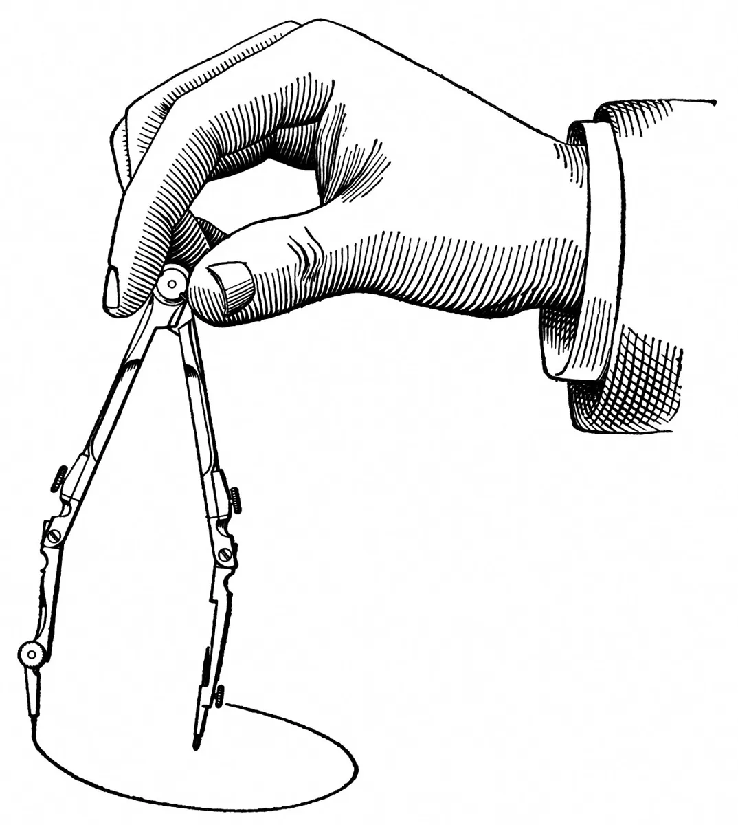
A rotation matrix always turns about the frame’s origin. To turn about some other point c (like a servo shaft on your table), slide c to the origin, rotate, then slide back: Tr(c) · R(θ) · Tr(−c). Points on c don’t move; everything else swings around it.
One joint = rotate, then go along the link
A revolute joint is exactly this pattern: Tr(axis) · R(θ) · Tr(L, 0) — go to the joint axis, turn by the joint angle, then go L along the (now turned) link. In Lessons 6–7 you will chain one of these per joint to build FK for a whole arm.
Visual
Visualise it: R and p separately
Watch the R block and the p column change independently. Swap the order of T₁ and T₂ to see why order matters.
Interactive · Transformation-matrix lab


Composed ᵖTᶜ = T₁·T₂ (planar teaching model, z fixed):
| 0.985 | -0.174 | 0.000 | 58.74 |
| 0.174 | 0.985 | 0.000 | 40.80 |
| 0.000 | 0.000 | 1.000 | 0.00 |
| 0.000 | 0.000 | 0.000 | 1.000 |
R block | p column · bottom [0 0 0 1]
Code lab
Code lab: five experiments with R and Tr
rotate_translate.py uses 3 × 3 homogeneous matrices on a flat table (the 2D version of Lesson 4’s 4 × 4). R(deg) rotates, Tr(x, y) translates, mul() multiplies any number of matrices and apply() moves a point. Each part tests one idea from the concept section.
# rotate_translate.py - the two pieces of every rigid motion, and why their ORDER matters.
# 2D homogeneous transforms (3x3) on a flat table, units cm and degrees.
import math


def R(deg):
    c, s = math.cos(math.radians(deg)), math.sin(math.radians(deg))
    return [[c, -s, 0.0], [s, c, 0.0], [0.0, 0.0, 1.0]]


def Tr(x, y):
    return [[1.0, 0.0, x], [0.0, 1.0, y], [0.0, 0.0, 1.0]]


def mul(*Ms):
    out = [[1.0 if i == j else 0.0 for j in range(3)] for i in range(3)]
    for M in Ms:
        out = [[sum(out[i][k] * M[k][j] for k in range(3)) for j in range(3)] for i in range(3)]
    return out


def apply(M, p):
    return (M[0][0] * p[0] + M[0][1] * p[1] + M[0][2], M[1][0] * p[0] + M[1][1] * p[1] + M[1][2])


def fmt(p):
    return f"({p[0] + 0.0:6.2f}, {p[1] + 0.0:6.2f})"


tip = (10.0, 0.0)          # the tip of a 10 cm link, in the link's own frame

print("1) Order matters: rotate 90°, then move 5 cm along x  vs  move first, then rotate")
print(f"   R(90) then Tr(5,0):  M = Tr(5,0) @ R(90) -> tip at {fmt(apply(mul(Tr(5, 0), R(90)), tip))}")
print(f"   Tr(5,0) then R(90):  M = R(90) @ Tr(5,0) -> tip at {fmt(apply(mul(R(90), Tr(5, 0)), tip))}")

print("\n2) A pure rotation still MOVES points that are not on the axis")
for p in ((0.0, 0.0), (10.0, 0.0), (20.0, 0.0)):
    q = apply(R(30), p)
    print(f"   point {fmt(p)} rotated 30° about the origin -> {fmt(q)}  moved {math.dist(p, q):5.2f} cm")

print("\n3) Rotating about a point that is NOT the origin: Tr(c) @ R(a) @ Tr(-c)")
c = (25.0, 10.0)                                         # e.g. a servo axis on the table
M = mul(Tr(*c), R(90), Tr(-c[0], -c[1]))
for p in ((35.0, 10.0), (25.0, 10.0)):
    print(f"   {fmt(p)} turned 90° about {fmt(c)} -> {fmt(apply(M, p))}")

print("\n4) A joint = rotate about the joint axis, then translate along the link")
for theta in (0, 45, 90):
    M = mul(Tr(25.0, 10.0), R(theta), Tr(10.0, 0.0))     # axis at (25,10), 10 cm link
    print(f"   joint {theta:3d}° -> link tip at {fmt(apply(M, (0.0, 0.0)))}")

print("\n5) Wrong aim vs wrong place: a pen 12 cm from the wrist")
good = mul(Tr(30.0, 0.0), R(0))
wrong_place = mul(Tr(31.0, 0.0), R(0))                   # 1 cm translation error
wrong_aim = mul(Tr(30.0, 0.0), R(5))                     # 5 deg rotation error
pen = (12.0, 0.0)
for name, M in (("correct", good), ("1 cm wrong place", wrong_place), ("5° wrong aim", wrong_aim)):
    p = apply(M, pen)
    print(f"   {name:<17} -> pen tip {fmt(p)}  error {math.dist(p, apply(good, pen)):4.2f} cm")
Output (run with python3 rotate_translate.py)
1) Order matters: rotate 90°, then move 5 cm along x  vs  move first, then rotate
   R(90) then Tr(5,0):  M = Tr(5,0) @ R(90) -> tip at (  5.00,  10.00)
   Tr(5,0) then R(90):  M = R(90) @ Tr(5,0) -> tip at (  0.00,  15.00)

2) A pure rotation still MOVES points that are not on the axis
   point (  0.00,   0.00) rotated 30° about the origin -> (  0.00,   0.00)  moved  0.00 cm
   point ( 10.00,   0.00) rotated 30° about the origin -> (  8.66,   5.00)  moved  5.18 cm
   point ( 20.00,   0.00) rotated 30° about the origin -> ( 17.32,  10.00)  moved 10.35 cm

3) Rotating about a point that is NOT the origin: Tr(c) @ R(a) @ Tr(-c)
   ( 35.00,  10.00) turned 90° about ( 25.00,  10.00) -> ( 25.00,  20.00)
   ( 25.00,  10.00) turned 90° about ( 25.00,  10.00) -> ( 25.00,  10.00)

4) A joint = rotate about the joint axis, then translate along the link
   joint   0° -> link tip at ( 35.00,  10.00)
   joint  45° -> link tip at ( 32.07,  17.07)
   joint  90° -> link tip at ( 25.00,  20.00)

5) Wrong aim vs wrong place: a pen 12 cm from the wrist
   correct           -> pen tip ( 42.00,   0.00)  error 0.00 cm
   1 cm wrong place  -> pen tip ( 43.00,   0.00)  error 1.00 cm
   5° wrong aim      -> pen tip ( 41.95,   1.05)  error 1.05 cm
Try it: set the translations to zero and change only the angle, then set the angle to zero and change only the translation. Watch R and p change independently.
Interactive · Transformation-matrix lab
Composed ᵖTᶜ = T₁·T₂ (planar teaching model, z fixed):
| 0.985 | -0.174 | 0.000 | 58.74 |
| 0.174 | 0.985 | 0.000 | 40.80 |
| 0.000 | 0.000 | 1.000 | 0.00 |
| 0.000 | 0.000 | 0.000 | 1.000 |
R block | p column · bottom [0 0 0 1]
Real world
Rotation and translation in the real world
- Tool calibration: finding a pen or welding tip on a robot is mostly finding the translation p from the flange; finding a camera needs both R and p.
- Robot joints: every revolute joint is a rotation about an axis followed by a translation along the link.
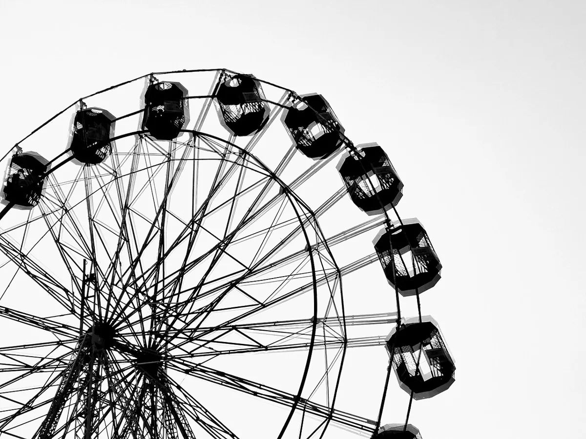
- Rides and wheels: a giant wheel or a merry-go-round only rotates, yet every seat travels — because it is off the axis.
- Debugging arms: engineers split a tip error into ‘wrong aim’ and ‘wrong place’ to know whether to check angles or lengths.
Bench build
Bench build: one servo joint, two predictions
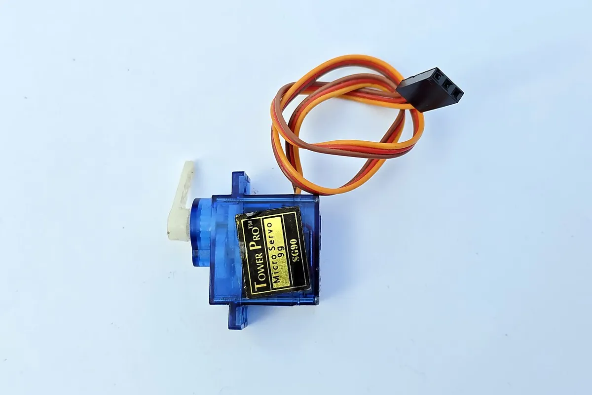
Glue a 10 cm card strip to a servo horn — that is one link on one joint. Fix the servo over a sheet of graph paper. single_link_tip.ino moves the servo to the angle you type and prints two predictions of the tip position on the paper: the right order (rotate about the axis, then go along the link) and a wrong order (rotate about the paper’s corner). Mark the real tip and see which one matches.
| From | To | Note |
|---|---|---|
| Servo red (+) | Separate 5–6 V supply + | NEVER the Arduino 5 V pin |
| Servo brown/black (−) | Supply − AND Arduino GND | Grounds joined |
| Servo orange/yellow (signal) | Arduino pin 6 | Signal only |
Set up the paper frame
Mark the paper’s origin in one corner, with x along the bottom edge and y up the side. Measure where the servo shaft is (AXIS_X, AXIS_Y).
Find the zero
Type 90. If the link is not along +x, change ZERO_OFFSET until it is.
Predict and mark
Type 45, 90 and 135. At each angle, prick a dot at the real tip and write both printed predictions beside it.
Compare
Measure each dot. Which prediction is within a few millimetres?
// single_link_tip.ino - one servo joint with a 10 cm card link: predict the tip, then measure it.
// Type an angle (0-180) in Serial Monitor. The servo moves, and the Arduino prints the tip position
// in the TABLE frame two ways: the right order  Tr(axis) * R(theta) * Tr(L)
//                              and a wrong order R(theta) * Tr(axis) * Tr(L)  (rotates about the table origin)
// Mark the real tip on paper and see which prediction matches.
// The SERVO runs from its OWN 5-6 V supply, NEVER from the Arduino 5 V pin. Join the grounds.
// Signal wire -> pin 6.
#include <Servo.h>
const int SERVO_PIN = 6;
const float AXIS_X = 25.0, AXIS_Y = 10.0;   // servo shaft position on your paper (cm) - MEASURE
const float LINK = 10.0;                    // shaft centre to tip (cm)
const float ZERO_OFFSET = -90.0;            // servo 90 -> link along +x of the table; adjust
Servo joint;

void setup() {
  joint.attach(SERVO_PIN);
  joint.write(90);
  Serial.begin(115200);
  Serial.println(F("Type an angle 0-180 and press Enter."));
}

void loop() {
  if (!Serial.available()) return;
  int a = Serial.parseInt();
  while (Serial.available()) Serial.read();
  a = constrain(a, 10, 170);                // keep clear of the end stops
  joint.write(a);
  float th = radians(a + ZERO_OFFSET);       // joint angle in the table frame
  // right order: rotate about the axis, THEN go along the rotated link
  float xr = AXIS_X + LINK * cos(th), yr = AXIS_Y + LINK * sin(th);
  // wrong order: go along x first, THEN rotate about the table origin by theta
  float px = AXIS_X + LINK, py = AXIS_Y;
  float xw = px * cos(th) - py * sin(th), yw = px * sin(th) + py * cos(th);
  Serial.print(F("servo ")); Serial.print(a);
  Serial.print(F(" -> right order tip (")); Serial.print(xr, 1); Serial.print(F(", ")); Serial.print(yr, 1);
  Serial.print(F(")  wrong order (")); Serial.print(xw, 1); Serial.print(F(", ")); Serial.print(yw, 1);
  Serial.println(F(")"));
}
Debugging
Debugging R and p
| Symptom | Likely cause | Fix |
|---|---|---|
| Tip swings around the wrong centre | Rotated about the origin, not the joint axis | Use Tr(c) · R · Tr(−c), or Tr(axis) · R · Tr(L) |
| Tip lands at a believable wrong place | Rotation and translation in the wrong order | Write the order in words first, then in matrices |
| Error grows with tool length | Aim (rotation) error | Check the wrist/tool angle, not the position |
| Error is the same size everywhere | Place (translation) error | Re-measure the offset |
| Bench: ‘right order’ prediction is off by a fixed angle | ZERO_OFFSET not set | Adjust until servo 90 points along +x |
| Bench: servo jitters or Arduino resets | Servo on Arduino power | Separate supply, joined grounds |
Think
Think about it
Think
A robot’s tool tip is 3 cm off from where it should be, in different directions at different poses. A friend says, “The tool is 3 cm too long — fix the offset.” Is that the most likely cause?
Experiment
Try it in the lab
About 30 minutes with the Python file, the transform lab and (optionally) the servo bench.
Experiment
Separate R and p
You will need
- `rotate_translate.py` and Python 3
- Transformation matrix lab (in your browser)
- Graph paper and a ruler
- Optional: Arduino UNO, micro servo, separate 5–6 V supply, card strip, jumper wires
Steps
- Walk it: in the classroom, do ‘turn right, 3 steps’ and then ‘3 steps, turn right’. Mark both end points with chalk.
- Run `rotate_translate.py`. Change Part 1 to 45° and predict both tip positions first.
- In Part 2, add the point (40, 0). How far does it move for 30°? Is it twice the 20 cm point?
- In Part 4, add joint angles 135° and 180°. Plot all five tips — what shape do they make?
- In Part 5, change the pen length to 24 cm. What happens to the 5° aim error?
- Optional: do the servo bench at three angles and compare with both predictions.
Interactive · Transformation-matrix lab
Composed ᵖTᶜ = T₁·T₂ (planar teaching model, z fixed):
| 0.985 | -0.174 | 0.000 | 58.74 |
| 0.174 | 0.985 | 0.000 | 40.80 |
| 0.000 | 0.000 | 1.000 | 0.00 |
| 0.000 | 0.000 | 0.000 | 1.000 |
R block | p column · bottom [0 0 0 1]
Changing the order changes the result. Rotation moves points in proportion to their distance from the axis, so aim errors grow with tool length while place errors stay the same size.
Knowledge check
Check your understanding
Knowledge check
1. In a 4 × 4 transform, the translation p is…
2. In rotate_translate.py Part 1, ‘rotate 90° then move 5 cm’ puts the 10 cm tip at (5, 10). ‘Move then rotate’ puts it at…
3. A pure rotation about the origin…
4. To rotate about a point c that is not the origin, use…
5. One revolute joint with a link of length L is…
6. A tip error that grows with tool length is most likely…
7. The servo in the bench build must be powered from…
Mini assignment
Hands-on assignment
Mini assignment
Rotation vs translation report
Show, with numbers and a drawing, how rotation and translation differ and why order matters.
Deliverables
- A drawing of Part 1 of the code: both orders, with the tip positions marked.
- A table from Part 2 with your extra point, and one sentence on how distance from the axis changes the movement.
- Part 4 extended to five angles, plotted on graph paper.
- Part 5 with two pen lengths, and a sentence explaining aim vs place errors.
- Optional: three servo-bench dots with both predictions and the measured positions.
Do this, step by step
- Run
python3 rotate_translate.pyand draw Part 1 on graph paper: both orders, with the tip marked each time. - In Part 2, add one point of your own farther from the axis. Record how much it moves for the same angle.
- Extend Part 4 to five angles (for example 0°, 30°, 60°, 90°, 120°) and plot the points; check they lie on one circle.
- Run Part 5 with two pen lengths and write one sentence on why a small aim error grows with length.
- Optional bench: mark three servo-bench dots, measure them with a ruler and compare with both predictions in the code.
Stuck? Hints, one at a time
- Rotating about a point c is Tr(c) · R · Tr(−c), read right to left.
- Points farther from the axis move more for the same angle: arc length = radius × angle (in radians).
- If two orders give the same answer, check whether the rotation centre is the origin.
Challenges (pick by level)
- 🟢 Easy: Write Tr(3, 4) as a 3 × 3 matrix and apply it to (1, 1).
- 🟢 Easy: Rotate (0, 10) by 90° about the origin by hand.
- 🟡 Medium: Show with code that two rotations about the same point commute, but rotations about two different points do not.
- 🟠 Hard-ish: Build the 2-link arm from Lesson 1 as Tr(0,0)·R(θ₁)·Tr(L1,0)·R(θ₂)·Tr(L2,0) and check it against the Lesson 1 FK formula.
- 🔴 Hard: Given only the measured bench dots, estimate AXIS_X, AXIS_Y and LINK (hint: three points on a circle).
- ⚫ Research: Look up ‘tool centre point (TCP) calibration’ for industrial robots and describe how it finds p.
Next step
You now have everything for Lesson 6 — Forward Kinematics: Concept: chain one ‘rotate, then go along the link’ per joint, and the tool pose falls out.
Look back: Lesson 4: Homogeneous Transformation Matrices. Next: Lesson 6: Forward Kinematics — Concept. Related: Stage 1: Transformations and Stage 1: Rotation.
Sources
- Wikipedia — Transformation matrix — rotation and translation as matrices; composition by multiplication; homogeneous coordinates for translation.
- Wikipedia — Rotation matrix — 2D rotation matrix and rotation about the origin.
- Modern Robotics — K. M. Lynch & F. C. Park (book home page, free preprint) — Chapter 3, Rigid-Body Motions.
- Photos and drawing: Wikimedia Commons (credits under each image).
Self-attested for now — keep artifacts in your lab notebook.
Complete
Today's goal
0 of 1 done today
Mark this lesson complete when you have worked the experiment, knowledge check, and assignment (even roughly).