
Robot Simulation & Digital Twin · Lesson 15
Building a Complete Digital Twin
Est. 60–75 min
Why
Why this lesson matters
Lessons 1–14 built every layer: the model, physics, sensors, controllers, the ROS 2 bridge, commands and tests. A digital twin puts them together and connects them to the real robot. The twin receives real data, stays close to the real arm, and tells you when the real arm starts to behave differently.
You will see why a model without data drifts, calibrate the twin from recorded data, detect a fault from the gap between twin and reality, and see what late data does. On the bench, the UNO runs a tiny twin of one joint and raises an alarm when your “real” joint stops following it.
Concept
Model + live data + comparison = twin
1. Simulation, digital shadow, digital twin
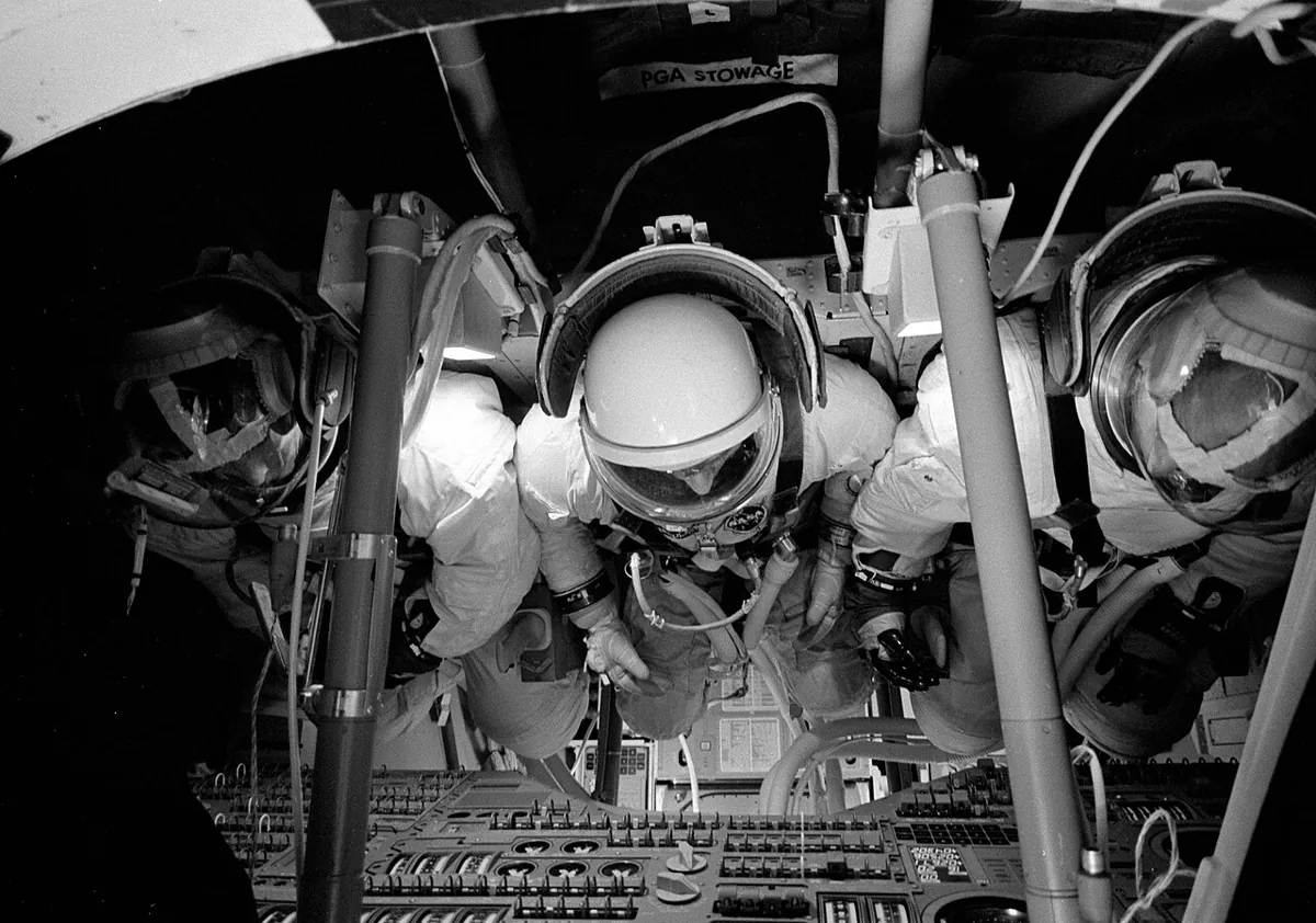
Wikipedia describes a digital twin as a computational model of a real product or system (the physical twin) used for simulation, testing, monitoring and maintenance. It also notes that a model running without data from its physical counterpart is only loosely called a twin. A common distinction: in a digital shadow, data flows one way, from the real asset to the model; in a digital twin, data flows both ways and the twin can also send commands back.
| Data real → model | Data model → real | Example | |
|---|---|---|---|
| Simulation | no | no | Lessons 6–14 on their own |
| Digital shadow | yes | no | RViz showing /joint_states from the real arm |
| Digital twin | yes | yes | Twin checks commands, predicts, and can stop the real arm |
2. The layers of your arm’s twin
- Model: URDF links, joints and limits (Lessons 2–5).
- Physics and contact: mass, inertia, friction (Lessons 6–9).
- Sensors: encoders and IMU with noise (Lesson 10).
- Controllers: the same control loop as the real arm (Lesson 11).
- Bridge and messages:
/joint_statesin, commands out, on one clock (Lessons 12–13). - Tests: the suite that must pass before commands go to the real arm (Lesson 14).
- New in this lesson: calibration from real data, live sync and a residual monitor.
3. Calibrate, sync, compare
Calibrate: record the real arm for a while, then choose the model values (gain, friction, offset) that make the twin match best — the smallest squared error. Always check on new data you did not fit on. Sync: regularly set the twin’s state to the latest real measurement, so small errors do not pile up. Compare: just before each sync, the twin predicted where the joint would be; the difference is the residual. Healthy arm → small residual. Something changes (loose coupling, worn gear, extra load) → residual grows → alarm.
Visual
Visualise it: the layers of a twin
The layers of a twin: model, world, physics, sensors, bridge, controller, vision/IK/trajectory and mission. Toggle layers, set the sync gap and run a test scenario. (Educational explorer, not a live plant twin.)
Interactive · Digital twin explorer · Educational approximation


Twin completeness: 100% · sync gap 15%
Select a scenario and Run test.
Stack composes Stages 7–11 conceptually. Maps to Gazebo / Isaac / Webots / MuJoCo stacks — no engine install. Not a live plant digital twin platform.
Code lab
Code lab: calibrate, sync and watch a twin
twin_sync_lab.py simulates a “real” joint whose true gain, friction and encoder offset are hidden from the twin, plus sensor noise. It compares a design-value twin, fits the twin to 20 s of recorded data, runs live sync with a residual alarm while a fault appears at t = 6 s, and shows the effect of late data. All values are examples. Run python3 twin_sync_lab.py (about 2 seconds).
"""Complete digital twin lab (Stage 12, Lesson 15) - Python 3 stdlib only.

A "real" joint (hidden from the twin: weaker motor, extra friction, encoder offset,
noise) and its digital twin (our simulation model) get the same commands.
  1. Model only (no data): how far does the twin drift from the real joint?
  2. Calibrate the twin from recorded data (least squares) -> drift shrinks
  3. Live sync + residual monitor: a fault at t = 6 s (loose coupling) -> alarm
  4. Late data: what a 0 / 50 / 200 ms delay does to the twin's picture
All numbers are EXAMPLES for a desk-arm joint, simulated at 100 Hz.
"""
import math, random

DT = 0.01
def command(t):                       # a repeating pick motion, radians
    return 0.8 * math.sin(0.6 * t) + (0.4 if (t % 5) < 2.5 else -0.4)

def step(q, cmd, gain, fric):
    v = gain * (cmd - q)              # simple position loop: speed ~ error
    v = v - fric if v > fric else (v + fric if v < -fric else 0.0)
    return q + v * DT

REAL = dict(gain=3.2, fric=0.06, offset=0.03)   # the twin does NOT know these
def run_real(T, fault_at=None, seed=15):
    rng, q, out = random.Random(seed), 0.0, []
    for k in range(int(T / DT)):
        t = k * DT
        g = REAL["gain"] * (0.35 if fault_at and t >= fault_at else 1.0)   # loose coupling
        q = step(q, command(t), g, REAL["fric"])
        out.append((t, command(t), q + REAL["offset"] + rng.gauss(0, 0.004)))   # encoder reading
    return out

def run_twin(data, gain, fric, offset, sync=False):
    q, err = data[0][2] - offset, []
    for t, cmd, meas in data:
        if sync and int(round(t / DT)) % 10 == 0:
            q = meas - offset                     # pull the twin to the real state at 10 Hz
        pred = q + offset
        err.append(meas - pred)
        q = step(q, cmd, gain, fric)
    return err

def rms(e): return math.sqrt(sum(x * x for x in e) / len(e))

print("=== 1. Model only (design values, no real data) ===")
data = run_real(20)
e = run_twin(data, gain=4.0, fric=0.0, offset=0.0)
print(f"design twin (gain 4.0, no friction, no offset): RMS gap {math.degrees(rms(e)):.2f} deg, "
      f"worst {math.degrees(max(map(abs, e))):.2f} deg")
print("-> a model that never sees real data is only a simulation, not a twin.")

print()
print("=== 2. Calibrate from 20 s of recorded data ===")
best = None
for g10 in range(20, 51):                                   # search gain 2.0..5.0
    for f100 in range(0, 13):                               # friction 0..0.12
        for o1000 in range(-50, 51, 5):                     # offset -0.05..0.05
            e = run_twin(data, g10 / 10, f100 / 100, o1000 / 1000)
            s = sum(x * x for x in e)
            if best is None or s < best[0]:
                best = (s, g10 / 10, f100 / 100, o1000 / 1000)
_, G, F, O = best
e = run_twin(data, G, F, O)
print(f"fitted: gain {G}, friction {F}, offset {O}   (hidden truth: 3.2, 0.06, 0.03)")
print(f"calibrated twin: RMS gap {math.degrees(rms(e)):.2f} deg, worst {math.degrees(max(map(abs, e))):.2f} deg")
fresh = run_real(20, seed=99)
e2 = run_twin(fresh, G, F, O)
print(f"check on NEW data (other seed): RMS gap {math.degrees(rms(e2)):.2f} deg")
print("-> always check calibration on data you did not fit on.")

print()
print("=== 3. Live sync + residual alarm (fault at t = 6.00 s) ===")
faulty = run_real(12, fault_at=6.0)
THRESH, NEED = math.radians(1.0), 3
for label, d in (("healthy", run_real(12, seed=7)), ("loose coupling", faulty)):
    res = run_twin(d, G, F, O, sync=True)
    checks = [(d[k][0], res[k]) for k in range(9, len(d), 10)]   # twin's 0.1 s-ahead prediction error, just before each sync
    run, alarm = 0, None
    for t, r in checks:
        run = run + 1 if abs(r) > THRESH else 0
        if run >= NEED and alarm is None:
            alarm = t
    worst = max(abs(r) for _, r in checks)
    print(f"{label:>15}: worst 0.1 s prediction error {math.degrees(worst):.2f} deg, alarm "
          + (f"at t = {alarm:.2f} s" if alarm else "none"))
print("-> residual = real - twin prediction. Small when healthy; it grows when the real")
print("   joint stops behaving like the model. Alarm needs > 1 deg on 3 checks in a row (no flicker).")

print()
print("=== 4. Late data ===")
for delay_ms in (0, 50, 200):
    n = delay_ms // 10
    lag = [abs(data[k][2] - data[k - n][2]) for k in range(max(n, 1), len(data))]
    print(f"state arrives {delay_ms:3d} ms late: twin shows the joint up to "
          f"{math.degrees(max(lag)):.2f} deg away from where it really is")
print("-> stamp every message (Lesson 12) and let the twin predict forward by the delay.")
Output (run with python3 twin_sync_lab.py)
=== 1. Model only (design values, no real data) ===
design twin (gain 4.0, no friction, no offset): RMS gap 3.20 deg, worst 7.25 deg
-> a model that never sees real data is only a simulation, not a twin.

=== 2. Calibrate from 20 s of recorded data ===
fitted: gain 3.3, friction 0.06, offset 0.03   (hidden truth: 3.2, 0.06, 0.03)
calibrated twin: RMS gap 0.34 deg, worst 1.75 deg
check on NEW data (other seed): RMS gap 0.34 deg
-> always check calibration on data you did not fit on.

=== 3. Live sync + residual alarm (fault at t = 6.00 s) ===
        healthy: worst 0.1 s prediction error 0.73 deg, alarm none
 loose coupling: worst 0.1 s prediction error 10.02 deg, alarm at t = 6.29 s
-> residual = real - twin prediction. Small when healthy; it grows when the real
   joint stops behaving like the model. Alarm needs > 1 deg on 3 checks in a row (no flicker).

=== 4. Late data ===
state arrives   0 ms late: twin shows the joint up to 0.00 deg away from where it really is
state arrives  50 ms late: twin shows the joint up to 7.97 deg away from where it really is
state arrives 200 ms late: twin shows the joint up to 26.62 deg away from where it really is
-> stamp every message (Lesson 12) and let the twin predict forward by the delay.Try it: switch twin layers on and off and watch the completeness score. Pick a scenario and press “Run test”. With Noisy sensors, move the sync gap slider above 40% to see the twin fail. (Educational explorer, not a live plant twin.)
Interactive · Digital twin explorer · Educational approximation
Twin completeness: 100% · sync gap 15%
Select a scenario and Run test.
Stack composes Stages 7–11 conceptually. Maps to Gazebo / Isaac / Webots / MuJoCo stacks — no engine install. Not a live plant digital twin platform.
Bench build: a one-joint twin on the UNO
twin_mirror.ino runs a twin of one joint. Pot A0 is the command. The twin moves towards it at a fixed 1.5 rad/s, like a servo would. Pot A1 is the real joint — you turn it by hand to follow. Every 50 ms the UNO compares them. Fall more than 0.25 rad behind for 0.5 s and the red ALARM LED lights. Type c to calibrate the offset between the pots, s to re-sync the twin.
| Part | Connection | Note |
|---|---|---|
| Pot 1 — command | outer legs 5V/GND, wiper A0 | where the joint should go |
| Pot 2 — real joint | outer legs 5V/GND, wiper A1 | turn by hand to follow |
| Green LED + 220 Ω | D5 → resistor → LED → GND | twin and real agree |
| Red LED + 220 Ω | D6 → resistor → LED → GND | ALARM |
// twin_mirror.ino - Stage 12, Lesson 15: Building a Complete Digital Twin
// The UNO runs a tiny digital twin of one joint and compares it with the "real"
// joint every 50 ms.
//   Pot A0 = COMMAND (where the joint should go)
//   Pot A1 = REAL joint position - you turn it by hand to follow the command
//   The twin model moves towards the command at a fixed speed (like a servo).
//   residual = real - twin. If it stays above 0.25 rad for 10 checks (0.5 s) -> ALARM.
//   Serial 'c' = calibrate: measure the average real-vs-twin offset over 1 s and remove it.
//   Serial 's' = sync: snap the twin to the real position (like re-syncing from /joint_states).
//
// Wiring (no motors):
//   Pot 1: outer legs 5V/GND, wiper A0 (command)
//   Pot 2: outer legs 5V/GND, wiper A1 (real joint)
//   Green LED + 220 ohm on D5 -> GND : in sync
//   Red LED + 220 ohm on D6 -> GND   : ALARM (twin and real disagree)
// Serial Monitor 115200, line ending "Newline".

const float RANGE_RAD = 270.0 * DEG_TO_RAD;   // example 270 degree pots
const float TWIN_SPEED = 1.5;                 // rad/s - the twin's model of the joint
const float THRESH = 0.25;                    // rad
const int NEED = 10;                          // checks in a row
const unsigned long STEP_MS = 50;

float twin = 0, offset = 0;
int over = 0;
bool alarm = false;
unsigned long last = 0;

float readRad(int pin) { return (analogRead(pin) / 1023.0 - 0.5) * RANGE_RAD; }

void calibrate() {
  Serial.println(F("CALIBRATE: hold both pots still for 1 s"));
  float sum = 0;
  for (int i = 0; i < 20; i++) { sum += readRad(A1) - twin; delay(50); }
  offset = sum / 20;
  Serial.print(F("offset = ")); Serial.print(offset, 3); Serial.println(F(" rad"));
}

void setup() {
  Serial.begin(115200);
  pinMode(5, OUTPUT);
  pinMode(6, OUTPUT);
  twin = readRad(A1);
  Serial.println(F("twin_mirror: c = calibrate offset, s = sync twin to real"));
}

void loop() {
  if (Serial.available()) {
    char ch = Serial.read();
    if (ch == 'c') calibrate();
    if (ch == 's') { twin = readRad(A1) - offset; over = 0; alarm = false; Serial.println(F("SYNC")); }
  }
  if (millis() - last < STEP_MS) return;
  last += STEP_MS;

  float cmd = readRad(A0);
  float maxStep = TWIN_SPEED * STEP_MS / 1000.0;
  float d = cmd - twin;
  twin += constrain(d, -maxStep, maxStep);     // the twin's model: limited speed

  float real = readRad(A1) - offset;
  float residual = real - twin;
  over = fabs(residual) > THRESH ? over + 1 : 0;
  if (over >= NEED && !alarm) { alarm = true; Serial.println(F("ALARM: real joint is not behaving like the twin")); }
  if (over == 0 && alarm) { alarm = false; Serial.println(F("back in sync")); }
  digitalWrite(5, alarm ? LOW : HIGH);
  digitalWrite(6, alarm ? HIGH : LOW);

  static int n = 0;
  if (++n % 10 == 0) {                          // print twice a second
    Serial.print(F("cmd=")); Serial.print(cmd, 2);
    Serial.print(F(" twin=")); Serial.print(twin, 2);
    Serial.print(F(" real=")); Serial.print(real, 2);
    Serial.print(F(" residual=")); Serial.println(residual, 3);
  }
}twin_mirror: c = calibrate offset, s = sync twin to real
cmd=0.01 twin=0.01 real=0.04 residual=0.030
> c
CALIBRATE: hold both pots still for 1 s
offset = 0.031 rad
cmd=0.82 twin=0.53 real=0.41 residual=-0.120
cmd=0.82 twin=0.82 real=0.79 residual=-0.030
cmd=-1.20 twin=0.07 real=0.62 residual=0.550
ALARM: real joint is not behaving like the twin
cmd=-1.20 twin=-1.20 real=-1.15 residual=0.050
back in sync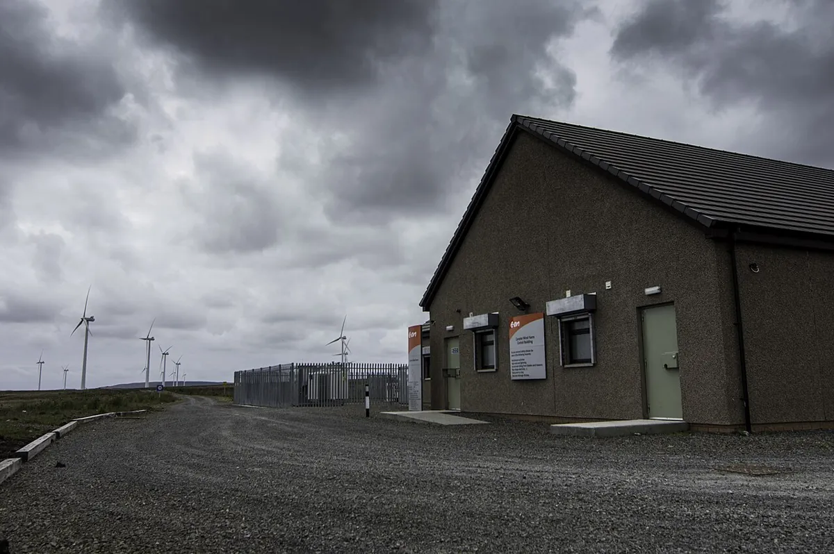
Debugging
| Symptom | Likely cause | Fix |
|---|---|---|
| Twin slowly drifts away from the real arm | no sync, or model values wrong | Sync from /joint_states regularly; calibrate |
| Constant residual even when still | encoder or zero offset | Calibrate the offset at a known pose |
| Many false alarms | threshold too tight, noise, or bad model | Require several readings in a row; improve the model; then tune threshold |
| Twin looks behind during fast moves | data delay | Stamp messages; predict forward by the delay; reduce latency |
| Calibration great on old data, bad on new | over-fitting one recording | Fit on one recording, check on another |
| Bench: ALARM never clears | twin and pot far apart after a long gap | Send s to re-sync |
Real world
Digital twins in the real world
- Manufacturing: Wikipedia describes twins fed by sensor data from machines for process monitoring — for example, force data showing whether a friction-stir weld has enough contact.
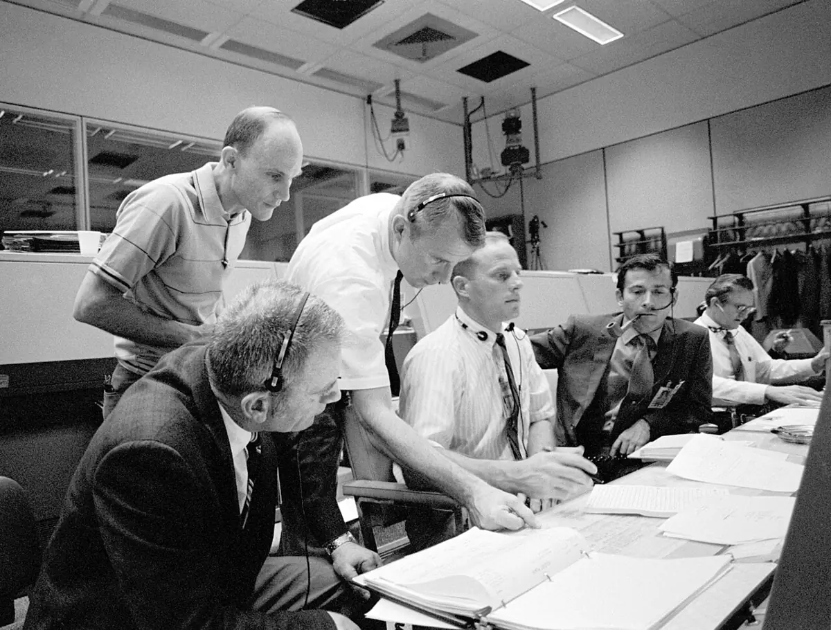
- Space: NASA used simulators alongside real missions, including to evaluate the Apollo 13 failure.
- Energy and buildings: twins are used to monitor and coordinate plants, grids and building systems.
- Your lab: a twin of the 6DOF desk arm that shows live joint states, predicts each move, checks commands with the test suite, and raises an alarm when the real arm stops behaving like the model.
Think
Think about it
Think
Your twin raises an ALARM on joint3 every afternoon around 3 PM, but the arm seems fine. What could be happening, and how would you find out?
Experiment
Try it in the lab
About 60 minutes. Python 3 for the script; an Arduino UNO, two pots, two LEDs and two 220 Ω resistors for the bench.
Experiment
Build, calibrate and break a twin
You will need
- `twin_sync_lab.py` (Python 3, no libraries)
- Digital twin explorer (in your browser)
- Arduino UNO, two 10 kΩ pots, green and red LEDs, two 220 Ω resistors
Steps
- Run `twin_sync_lab.py`. Change the hidden REAL friction to 0.09. Does calibration find it? What is the new RMS gap?
- In part 3, change the fault strength from 0.35 to 0.8 (a smaller fault). Is it still detected? How quickly?
- Change the alarm rule to need 1 check instead of 3. Does the healthy run now give a false alarm?
- Bench: follow the command slowly, then quickly, then stop following. Note the residual and when the alarm comes.
- Bench: skip calibration, then use `c`. How does the resting residual change?
- Interactive: turn off “ROS bridge” and run Nominal pick. Explain the result in one sentence.
Interactive · Digital twin explorer · Educational approximation
Twin completeness: 100% · sync gap 15%
Select a scenario and Run test.
Stack composes Stages 7–11 conceptually. Maps to Gazebo / Isaac / Webots / MuJoCo stacks — no engine install. Not a live plant digital twin platform.
A twin is only as good as its model and its data. Calibrate from real data, check on new data, sync often, compare with a residual, and alarm on a pattern, not one reading.
Knowledge check
Check your understanding
Knowledge check
1. What makes a digital twin different from a plain simulation?
2. In a digital shadow, data flows…
3. Why check calibration on new data?
4. The residual is…
5. Why need several readings over the threshold before an alarm?
6. In the script, a loose coupling appears at t = 6.00 s. The alarm comes at…
7. Joint states arrive 200 ms late during fast moves. The twin…
Mini assignment
Hands-on assignment
Mini assignment
A working twin plan for your desk arm
Bring all the Stage 12 layers together into one twin of your 6DOF desk arm and show it catching a problem.
Deliverables
- A one-page diagram of your twin: every layer, which lesson it came from, and every data flow (real → twin, twin → real) with topic names.
- A calibration report for at least one joint: fitted values, RMS gap on the fitting data and on new data.
- A residual monitor with a written alarm rule, and a log showing it catching a fault you made on purpose (in the script or on the bench).
- Bench log from `twin_mirror.ino` showing calibration, normal following, ALARM and back in sync.
Do this, step by step
- Draw your twin: every layer, the lesson it came from, and every data flow with topic names.
- Run
twin_sync_lab.pyand read the fitted gain, friction and offset. - Check the RMS gap on new data, not only on the fitting data.
- Write an alarm rule for the residual monitor and make a fault on purpose to test it.
- Bench: run
twin_mirror.inoand log calibration, normal following, ALARM and back in sync.
Stuck? Hints, one at a time
- The script’s
REALvalues are hidden from the twin. Compare your fit to them only at the end. - A good fit on old data but a bad one on new data means the model is copying noise.
- An alarm rule needs a size and a time, for example “residual over X for Y samples”.
Challenges (pick by level)
- 🟢 Beginner: Draw your twin’s layer diagram and label which are a digital shadow (one-way) and which would make it a full twin (two-way).
- 🟡 Intermediate: In
twin_sync_lab.py, make the twin predict forward by the delay in part 4 and show how much the error shrinks. - 🟠 Advanced: Write a Python script that reads
twin_mirror.inooutput over serial, plots real, twin and residual live, and saves a CSV. - 🔴 Expert: Build an rclpy node that subscribes to
/joint_statesfrom your arm (or Gazebo), runs a calibrated model of each joint, publishes residuals and an alarm topic. - ⚫ Research: Read the Wikipedia article on digital twins and its references on twin prototype, instance and aggregate. Design how an aggregate of 20 desk arms in a lab could predict which arm needs maintenance first.
Next step
You now have every piece. In Lesson 16 — Capstone: Build & Test a Simulated 6DOF Robot you will build the complete simulated 6DOF arm, test it, and use it as the twin of your real desk arm.
Look back: Lesson 14: Simulation-Based Testing. Next: Lesson 16: Capstone — Build & Test a Simulated 6DOF Robot. Related: Stage 10 — ROS 2.
Sources
- Wikipedia — Digital twin — definition, model without data, digital shadow vs twin, prototype/instance/aggregate, NASA Apollo 13 simulators, manufacturing monitoring.
- joint_state_broadcaster user docs (ros2_controllers, Jazzy) —
/joint_states, the real-data stream a twin listens to. - Photos: Wikimedia Commons (credits under each image).
Self-attested for now — keep artifacts in your lab notebook.
Complete
Today's goal
0 of 1 done today
Mark this lesson complete when you have worked the experiment, knowledge check, and assignment (even roughly).