
Math for Robotics · Lesson 11
Math → Robot Connection
Est. 35–45 min
Why
Why joint space and task space must stay friends
Concept
The big idea: angles in, tip pose out (FK intuition)
- Joint space: the vector of joint angles (and maybe prismatic lengths).
- Task space: tip position (and orientation) in a Cartesian frame.
- FK: given joints, compute tip — usually unique and straightforward (trig + transforms).
- IK: given tip, find joints — may have 0, 1, or many solutions (later stages).
- You already have the pieces: angles, trig, vectors, frames, R, t, H.
How it works
How it actually works, step by step
Read joint angles
From encoders or from your commanded setpoints (radians internally).
Build each link transform
Using length and joint angle — planar FK or a small H per joint.
Compose base → tip
Multiply along the chain (frame tree).
Read task-space pose
Tip origin and orientation in {base} or {world}.
Visual
Visualise it: pose from joint configuration
Change the pose controls and connect what you see to joint-space commands versus tip position in space.
Interactive · Robot pose / transformation demo
Tip (x, y)
(152.1, 75.4)
Tip yaw
-5.0°
Simplification: planar 2R arm. Each joint adds a rotation; tip pose is the product of link transforms — the same idea as homogeneous chains on a 6DOF arm.
Worked example
Worked example: 2DOF FK table
L1=15 cm, L2=12 cm. Several (q1,q2) pairs map to different tip locations — see the code lab table.
Code lab
Code lab: joint space → tip table
"""Stage 1 L11 — joint space → task space (planar 2DOF FK table)."""
import math

L1, L2 = 0.15, 0.12
configs = [(0, 0), (30, 0), (30, 45), (90, -60)]

print("q1°  q2°  |  tip_x cm  tip_y cm")
print("-" * 40)
for q1d, q2d in configs:
    q1, q2 = math.radians(q1d), math.radians(q2d)
    x = L1*math.cos(q1) + L2*math.cos(q1+q2)
    y = L1*math.sin(q1) + L2*math.sin(q1+q2)
    print(f"{q1d:3d}  {q2d:3d}  |  {x*100:7.2f}   {y*100:7.2f}")

print()
print("Joint space = the angles you command.")
print("Task space  = where the tip actually is (here in cm).")
Expected output
q1°  q2°  |  tip_x cm  tip_y cm
----------------------------------------
  0    0  |    27.00      0.00
 30    0  |    23.38     13.50
 30   45  |    16.10     19.09
 90  -60  |    10.39     21.00

Joint space = the angles you command.
Task space  = where the tip actually is (here in cm).
Real world
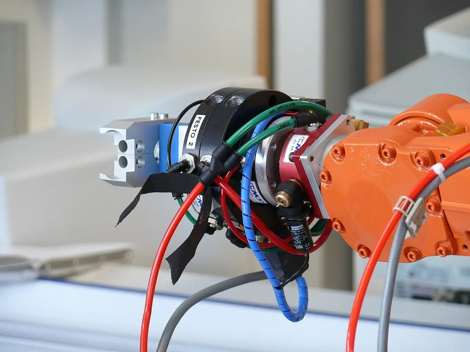
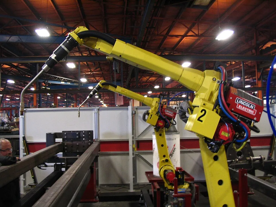
Industrial arms speaking maths
Mistakes
Common mistakes and confusions
Hardware & safety
Hardware lab and safety notes
Two potentiometers (or two servos) on a cardboard two-link arm turn this lesson into a real joint-space → task-space machine: knobs are joint space, the pen tip is task space.
- Build on Lesson 2: pot 1 → A0 (q1), pot 2 → A1 (q2), both between 5 V and GND.
- Print q1, q2 and the FK tip with L1 = 15 cm, L2 = 12 cm, like
fk_joint_space.py. - If you use servos instead, give them a separate 5–6 V supply and common ground.
Debugging
Debugging: when it doesn’t work
| Symptom | Likely cause | Fix |
|---|---|---|
| Tip table doesn't match the script | Link 2 angle not added to q1 | Link 2 absolute angle = q1 + q2 |
| Commanded (x, y) into a joint API | Mixed task space and joint space | Joint APIs take angles; run IK first |
| IK returns nothing | Target is outside reach (> L1 + L2) | Check |target| ≤ L1 + L2 before IK |
| Arm picks the “other” elbow | Two IK solutions exist | Choose elbow-up or elbow-down explicitly |
Think
Think about it
Think
Why is FK usually easier than IK for the same arm?
Experiment
Try it in the lab: FK worksheet
Experiment
FK worksheet
You will need
- fk_joint_space.py
- Notebook
Steps
- Reproduce two rows of the table by hand with a calculator.
- Change L2 in the script and predict whether reach grows or shrinks.
- Mark which configs look “elbow up” vs “elbow down” on a sketch.
Interactive · Robot pose / transformation demo
Tip (x, y)
(152.1, 75.4)
Tip yaw
-5.0°
Simplification: planar 2R arm. Each joint adds a rotation; tip pose is the product of link transforms — the same idea as homogeneous chains on a 6DOF arm.
Hand calc and script should match within ~0.1 cm.
Knowledge check
Check your understanding
Knowledge check
1. Joint space means…
2. FK maps…
3. IK may have…
4. This stage’s tools that build FK include…
Practice quiz
Mini assignment
Hands-on assignment
Mini assignment
FK / IK postcard
One postcard: front = FK diagram (joints → tip). Back = IK warning (may fail / multi-solution).
Deliverables
- Postcard or half-page diagram
Do this, step by step
- Reproduce rows 2 and 3 of the
fk_joint_space.pytable by hand. - Add a row for q1 = 60°, q2 = −30° in the script and predict the tip first.
- Mark which configurations are elbow-up and which elbow-down.
- Make the FK / IK postcard.
Stuck? Hints, one at a time
- Hint 1: Row 2: (15·cos30° + 12·cos30°, 15·sin30° + 12·sin30°) = (23.38, 13.50) cm.
- Hint 2: New row: link 2 absolute angle = 60° − 30° = 30°, so tip ≈ (7.50 + 10.39, 12.99 + 6.00) = (17.89, 18.99) cm.
- Hint 3: A negative q2 bends the elbow one way, positive the other — draw both to see.
Challenges (pick by level)
- 🟢 Easy: What is the maximum reach of this arm? (27 cm.)
- 🟡 Medium: Find two (q1, q2) pairs that reach the same tip.
- 🟠 Hard: Write a 2-link IK using the law of cosines and check FK(IK(p)) ≈ p.
Next step
Next, Lesson 12: Capstone — Locate & Move puts everything together. Related: full IK in Stage 8 — Kinematics & IK.
Sources
- Wikipedia — Forward kinematics
- Wikipedia — Inverse kinematics
- Wikipedia — Robot kinematics
- Photos: Wikimedia Commons (credits under each image).
Self-attested for now — keep artifacts in your lab notebook.
Complete
Today's goal
0 of 1 done today
Mark this lesson complete when you have worked the experiment, knowledge check, and assignment (even roughly).