
Trajectory Planning & Motion Generation · Lesson 02
Configuration Space & Robot Motion
Est. 45–60 min
Why
Why this lesson matters
That square is the robot’s configuration space, or C-space. It is one of the most useful ideas in robotics because it turns a complicated question — “will any part of this arm hit anything while it moves?” — into a simple picture: a single point moving through a map that has forbidden regions. Every trajectory you plan in this stage is, in the end, a curve in C-space with a clock attached.
By the end of this lesson you will be able to: define configuration, degrees of freedom and C-space; draw the C-space of a 2-joint arm with joint limits and an obstacle; explain why a straight line in C-space can still hit something; plan a simple detour with a via point; and use a hand-moved teach arm that lights a red LED when your pose is inside the forbidden region.
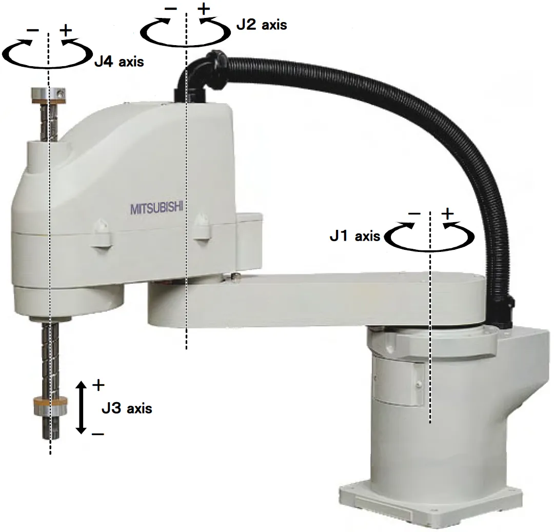
Concept
One point for the whole robot
Configuration, degrees of freedom, C-space
| Term | Meaning (from Modern Robotics, Ch. 2) | For our 2-link arm |
|---|---|---|
| Configuration | A complete specification of the position of every point of the robot | (θ₁, θ₂) — two numbers fix the whole arm |
| Degrees of freedom (dof) | The smallest number of real numbers needed to describe the configuration | 2 |
| Configuration space (C-space) | The space of all configurations of the robot | All pairs (θ₁, θ₂) — a 2-D map |
| Task space | A space where the task is naturally described | The x–y position of the pen tip on the table |
Notice the shift in thinking. In task space you see a whole arm with two links that can bump into things. In C-space the entire arm becomes a single point. Your Stage 6 six-joint arm is one point in a 6-dimensional C-space — we cannot draw six dimensions, but the 2-D case builds the right instinct.
The square that is really a doughnut
If each joint can turn all the way round, θ₁ = 360° is the same pose as θ₁ = 0°. So the right edge of the square is glued to the left edge, and the top to the bottom. *Modern Robotics* points out that the C-space of a 2R arm is therefore a torus — the surface of a doughnut — cut open and laid flat. Real arms usually have joint limits (cables, hard stops, the table), which chop the doughnut back into a plain rectangle. In this lesson we use shoulder 0°–180° and elbow −150° to +150°.
Free space and C-obstacles
Pick a dot in the square, draw the arm in that pose, and check whether any part of it overlaps the bottle. If it does, shade the dot. The shaded set is the C-obstacle (C_obs); the rest is free space (C_free). Joint limits are treated as obstacles too. Planning a collision-free motion then means: find a curve from the start dot to the goal dot that stays in C_free. If the C-obstacles cut C_free into separate islands and start and goal are on different islands, no collision-free motion exists at all.
Motion = a curve in C-space
- A path is a curve in C-space from start to goal (no clock).
- A trajectory is that curve with time attached: θ(t) traces it at a chosen speed.
- The simplest path is a straight line in joint space: every joint moves from start to goal together. It is easy and always respects box-shaped joint limits, but it can still pass through a C-obstacle.
- A via point (waypoint) bends the path around trouble: start → via → goal. Lesson 5 will make waypoints a full tool.
Visual
Visualise it: the arm’s world as a map
Scrub along the waypoints. Each moment is one configuration; the whole motion is a curve through configuration space.
Interactive · Trajectory concept explorer


A pose is a snapshot. A trajectory is a time-parameterized path — where to be and when. Scrub progress; toggle "hold pose" to feel the difference.
Code lab
Code lab: draw a C-space and plan around a bottle
cspace.py uses the same arm as Stage 8 (L1 = 10 cm, L2 = 8 cm). A round bottle stands at (10, 12) cm with radius 3 cm. For every shoulder angle (10° steps) and elbow angle (15° steps) it checks 41 points along the two links against the bottle and prints a text map. Then it tests a straight joint-space move and a detour. Run python3 cspace.py.
"""cspace.py — Stage 9, Lesson 2
Draw the configuration space (C-space) of a 2-link planar arm.
  L1 = 10 cm, L2 = 8 cm, shoulder at (0, 0).
  One round obstacle (a water bottle seen from above): centre (10, 12) cm, radius 3 cm.
  Joint limits: shoulder 0..180 deg, elbow -150..150 deg (example limits).
Every (theta1, theta2) pair is ONE point in C-space. We mark it
  '.' free   '#' arm hits the bottle   ' ' outside joint limits
then test two plans from START to GOAL.
"""
import math

L1, L2 = 10.0, 8.0
OBS_C, OBS_R = (10.0, 12.0), 3.0
SH_LIM, EL_LIM = (0, 180), (-150, 150)


def fk_points(t1, t2, n=20):
    """Points along both links (for collision checking), angles in degrees."""
    a, b = math.radians(t1), math.radians(t1 + t2)
    ex, ey = L1 * math.cos(a), L1 * math.sin(a)
    pts = [(L1 * k / n * math.cos(a), L1 * k / n * math.sin(a)) for k in range(n + 1)]
    pts += [(ex + L2 * k / n * math.cos(b), ey + L2 * k / n * math.sin(b)) for k in range(1, n + 1)]
    return pts


def hits(t1, t2):
    return any(math.hypot(x - OBS_C[0], y - OBS_C[1]) < OBS_R for x, y in fk_points(t1, t2))


def within_limits(t1, t2):
    return SH_LIM[0] <= t1 <= SH_LIM[1] and EL_LIM[0] <= t2 <= EL_LIM[1]


def cell(t1, t2):
    if not within_limits(t1, t2):
        return ' '
    return '#' if hits(t1, t2) else '.'


print("Part 1 - C-space map (rows: elbow theta2 from +150 down to -150, cols: shoulder theta1 0..180, 10 deg steps)")
print("        " + "".join("|" if t1 % 30 == 0 else " " for t1 in range(0, 181, 10)))
free = blocked = 0
for t2 in range(150, -151, -15):
    row = ""
    for t1 in range(0, 181, 10):
        c = cell(t1, t2)
        free += c == '.'
        blocked += c == '#'
        row += c
    print(f"{t2:>6d}  {row}")
print(f"free cells {free}, blocked cells {blocked} ({100*blocked/(free+blocked):.0f}% of the allowed square is C-obstacle)")
print("(the | marks above the map are theta1 = 0, 30, 60, 90, 120, 150, 180 deg)")

START, GOAL = (0.0, 30.0), (120.0, 30.0)


def check_line(a, b, steps=80):
    """Straight line in joint space from a to b; return first colliding config or None."""
    for k in range(steps + 1):
        s = k / steps
        q = (a[0] + s * (b[0] - a[0]), a[1] + s * (b[1] - a[1]))
        if not within_limits(*q) or hits(*q):
            return q
    return None


print("\nPart 2 - is the straight joint-space line START -> GOAL free?")
print(f"START {START}  GOAL {GOAL}  start free: {not hits(*START)}  goal free: {not hits(*GOAL)}")
bad = check_line(START, GOAL)
print("plan A (straight line):", "FREE" if bad is None else f"BLOCKED near theta = ({bad[0]:.0f}, {bad[1]:.0f})")

VIA = (0.0, 120.0)   # 'tuck the elbow first'
legs = [check_line(START, VIA), check_line(VIA, GOAL)]
print(f"plan B (via {VIA}):", "FREE" if all(x is None for x in legs) else f"BLOCKED {legs}")

print("\nPart 3 - let the computer try every via point on the grid")
good = [(a, b) for a in range(0, 181, 10) for b in range(-150, 151, 15)
        if check_line(START, (a, b)) is None and check_line((a, b), GOAL) is None]
print(f"{len(good)} single via points give a free two-leg plan, e.g. {good[:5]}")

print("\nPart 4 - same configs in task space (where is the tip?)")
for name, q in (("START", START), ("VIA", VIA), ("GOAL", GOAL)):
    x, y = fk_points(*q)[-1]
    print(f"{name:5s} theta = ({q[0]:5.1f}, {q[1]:6.1f})  tip = ({x:6.2f}, {y:6.2f}) cm")
Output (run with python3 cspace.py)
Part 1 - C-space map (rows: elbow theta2 from +150 down to -150, cols: shoulder theta1 0..180, 10 deg steps)
        |  |  |  |  |  |  |
   150  ...................
   135  ...................
   120  ...................
   105  ...................
    90  .#.................
    75  .##................
    60  ..##...............
    45  ...##..............
    30  ...###.............
    15  ....##.............
     0  ....###............
   -15  .....##............
   -30  .....###...........
   -45  ......###..........
   -60  .......##..........
   -75  ........##.........
   -90  .........#.........
  -105  ...................
  -120  ...................
  -135  ...................
  -150  ...................
free cells 371, blocked cells 28 (7% of the allowed square is C-obstacle)
(the | marks above the map are theta1 = 0, 30, 60, 90, 120, 150, 180 deg)

Part 2 - is the straight joint-space line START -> GOAL free?
START (0.0, 30.0)  GOAL (120.0, 30.0)  start free: True  goal free: True
plan A (straight line): BLOCKED near theta = (28, 30)
plan B (via (0.0, 120.0)): FREE

Part 3 - let the computer try every via point on the grid
15 single via points give a free two-leg plan, e.g. [(0, 105), (0, 120), (0, 135), (0, 150), (10, 135)]

Part 4 - same configs in task space (where is the tip?)
START theta = (  0.0,   30.0)  tip = ( 16.93,   4.00) cm
VIA   theta = (  0.0,  120.0)  tip = (  6.00,   6.93) cm
GOAL theta = (120.0, 30.0) tip = (-11.93, 12.66) cmTry it: move the q1 and q2 sliders and watch the arm and its single point in C-space. The blocked region here is a simplified box-shaped C-obstacle. Find two free poses whose straight line crosses it.
Interactive · Configuration space explorer · Educational 2R


Educational C-space sketch for planar 2R — not OMPL / not MoveIt / not 6DOF C-space.
Real world
C-space in the real world
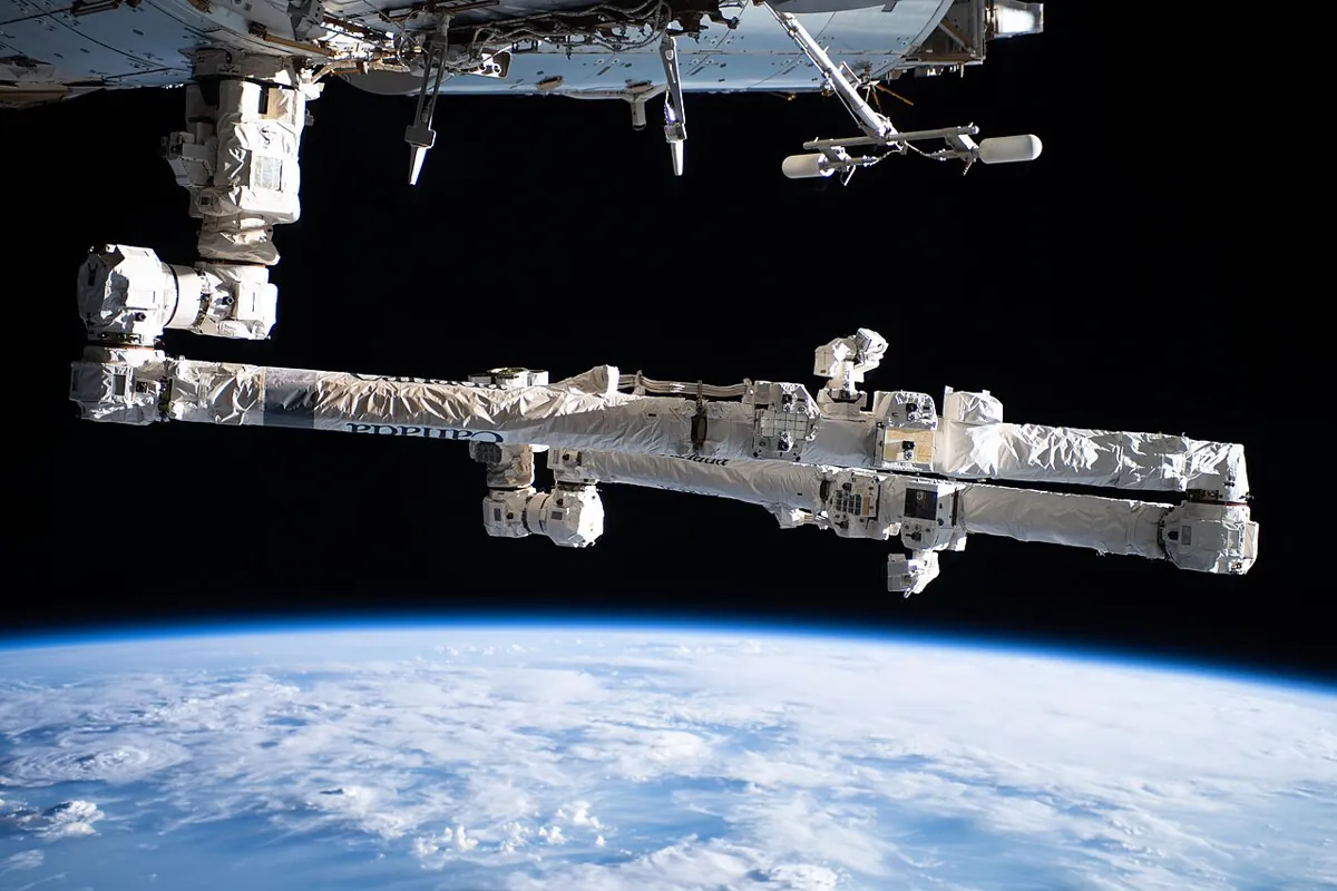
- Space robotics: Canadarm2 on the International Space Station has seven joints. Before a move, mission teams check the planned motion so no part of the arm comes near the station structure.
- Factory cells: offline programming tools simulate each robot move in a 3-D model of the cell and flag poses where the arm or tool would hit fixtures — a C-obstacle check in practice.
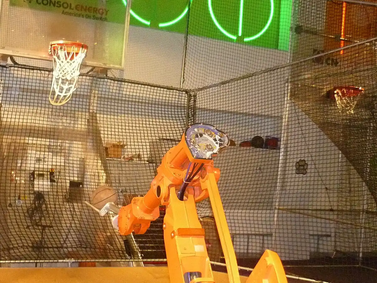
- Motion-planning software (for example the MoveIt framework you will meet with ROS) samples configurations, checks each for collision, and joins the free ones into a path.
- Video games and animation use the same idea to move characters and cameras without passing through walls.
Bench build
Bench build: a C-space probe with a warning light
Reuse the passive teach arm from Stage 8, Lesson 1 (two 10 kΩ pots as joints, 10 cm and 8 cm links). cspace_probe.ino reads both angles, checks the same virtual bottle as the Python code and lights a red LED when your pose is inside the C-obstacle, green when free. It also prints CSV lines you can plot.
| From | To | Note |
|---|---|---|
| Each pot, outer pins | 5 V and GND | — |
| Shoulder pot wiper | A0 | θ₁ |
| Elbow pot wiper | A1 | θ₂ |
| D7 → 220 Ω → red LED → GND | — | HIT |
| D6 → 220 Ω → green LED → GND | — | FREE |
Calibrate
Open Serial Monitor (115200). Put each joint at 0° and 90° with a set square, note the raw readings (add a temporary
Serial.println(analogRead(A0))if needed) and type them into SH_0, SH_90, EL_0, EL_90.Mark the bottle
Draw a 3 cm-radius circle centred at (10, 12) cm on graph paper under the arm. That is your virtual bottle.
Probe
Move the arm slowly. The red LED should light exactly when a link passes over the circle.
Trace a path
Clear the monitor, do the Plan B motion (tuck elbow, swing, unfold), copy the CSV into a spreadsheet and draw a scatter plot of t1 vs t2. You have drawn your hand’s path in C-space.
// cspace_probe.ino — Stage 9, Lesson 2
// A hand-moved 2-link "teach arm" (two 10 kΩ pots, no motors) that knows
// where it is in C-space and warns you when the arm would hit a virtual bottle.
//   L1 = 10 cm, L2 = 8 cm. Virtual bottle: centre (10, 12) cm, radius 3 cm (same as cspace.py).
// Wiring: shoulder pot wiper -> A0, elbow pot wiper -> A1, pot ends -> 5 V and GND.
//         Red LED + 220 Ω -> D7 -> GND (HIT), green LED + 220 Ω -> D6 -> GND (FREE).
// Output (115200 baud): CSV "t1,t2,state" every 100 ms — paste it into a spreadsheet
// and plot t1 (x) against t2 (y) to see your hand motion as a line in C-space.

#include <math.h>

const float L1 = 10.0, L2 = 8.0;
const float OBS_X = 10.0, OBS_Y = 12.0, OBS_R = 3.0;
// Calibration: raw ADC readings at 0° and 90° for each joint (measure yours!)
const int SH_0 = 205, SH_90 = 512;   // shoulder
const int EL_0 = 512, EL_90 = 819;   // elbow (0° = straight, +90° = folded left)
const int LED_HIT = 7, LED_FREE = 6;

float rawToDeg(int raw, int r0, int r90) {
  return (raw - r0) * 90.0 / (float)(r90 - r0);
}

bool hitsBottle(float t1deg, float t2deg) {
  float a = radians(t1deg), b = radians(t1deg + t2deg);
  float ex = L1 * cos(a), ey = L1 * sin(a);
  for (int k = 0; k <= 20; k++) {            // 21 points on each link
    float f = k / 20.0;
    float x1 = L1 * f * cos(a), y1 = L1 * f * sin(a);
    float x2 = ex + L2 * f * cos(b), y2 = ey + L2 * f * sin(b);
    if (hypot(x1 - OBS_X, y1 - OBS_Y) < OBS_R) return true;
    if (hypot(x2 - OBS_X, y2 - OBS_Y) < OBS_R) return true;
  }
  return false;
}

int readAvg(int pin) {           // average 8 readings to calm ADC noise
  long sum = 0;
  for (int i = 0; i < 8; i++) sum += analogRead(pin);
  return sum / 8;
}

void setup() {
  Serial.begin(115200);
  pinMode(LED_HIT, OUTPUT);
  pinMode(LED_FREE, OUTPUT);
  Serial.println(F("t1,t2,state"));
}

void loop() {
  float t1 = rawToDeg(readAvg(A0), SH_0, SH_90);
  float t2 = rawToDeg(readAvg(A1), EL_0, EL_90);
  bool hit = hitsBottle(t1, t2);
  digitalWrite(LED_HIT, hit ? HIGH : LOW);
  digitalWrite(LED_FREE, hit ? LOW : HIGH);
  Serial.print(t1, 1); Serial.print(',');
  Serial.print(t2, 1); Serial.print(',');
  Serial.println(hit ? F("HIT") : F("FREE"));
  delay(100);
}Debugging
Debugging C-space checks
| Symptom | Likely cause | Fix |
|---|---|---|
| Map is all free even with the bottle close | Only the tip is checked, not points along the links | Sample many points on both links |
| Map looks mirrored | Elbow angle sign convention differs from your arm | Write down which way +θ₂ bends and match the code |
| Straight line passes but the arm still hits | Too few samples along the line | Increase steps, or make samples closer than the obstacle size |
| Red LED flickers at the edge | ADC noise near the boundary | Average readings (already 8×) or add a small safety margin to OBS_R |
| Search finds no via point | Start and goal on separate free islands, or grid too coarse | Try a finer grid or two via points; check the map |
Think
Think about it
Think
Arjun moves the bottle 2 cm closer to the robot base. Without running any code, will the shaded band in C-space get bigger or smaller? Could the arm ever become completely “trapped” on one side?
Experiment
Try it in the lab
About 30 minutes with cspace.py, graph paper and the browser labs (bench probe optional).
Experiment
Map the arm’s world
You will need
- `cspace.py` and Python 3
- Graph paper, two coloured pens
- Configuration-space explorer and trajectory explorer (in your browser)
- Optional: teach arm (2 pots), Arduino UNO, red and green LEDs, two 220 Ω resistors
Steps
- Run `cspace.py`. Copy the map onto graph paper and colour the C-obstacle.
- Draw the straight line from START to GOAL on your map. Mark where it enters the band.
- Draw Plan B (start → via → goal). Check it stays in white cells.
- Change OBS_R to 2 cm, then 4 cm. How does the band change? Does plan A ever become free?
- Change OBS_C to (9, 9). Is there still any free path from START to GOAL? Why?
- Optional: probe the bench arm and plot your own C-space trace from the CSV.
Interactive · Trajectory concept explorer
A pose is a snapshot. A trajectory is a time-parameterized path — where to be and when. Scrub progress; toggle "hold pose" to feel the difference.
A small round object in task space becomes a stretched, curved region in C-space. Straight lines in C-space are simple but not automatically safe. A via point can bend the path around the C-obstacle — as long as start and goal are on the same free island.
Knowledge check
Check your understanding
Knowledge check
1. The configuration space of a robot is…
2. How many dimensions does the C-space of a 6-joint arm have?
3. Without joint limits, the C-space of a 2R arm (both joints turning fully) has the shape of a…
4. A C-obstacle is…
5. Start and goal are both collision-free. Is the straight joint-space line between them guaranteed safe?
6. In `cspace.py`, Plan B works because…
7. Free space splits into two islands with start on one and goal on the other. Then…
Mini assignment
Hands-on assignment
Mini assignment
Your table, your C-space
Draw the C-space of a real 2-joint arm on your own desk with a real obstacle, and plan a safe motion through it.
Deliverables
- Measure your arm (or use 10 cm / 8 cm) and place a real object (bottle, pencil box) on graph paper. Record its centre and size.
- Edit `cspace.py` with your numbers (approximate the object as a circle) and attach the map.
- Choose a start and a goal pose that are both free but whose straight line collides. Show the blocked point.
- Find a via point (by hand on the map or with Part 3) that makes a free two-leg plan. Draw both views: C-space map and top view of the arm.
- Write four sentences explaining configuration, dof, C_free and C_obs in your own words.
- Optional: probe the plan with the teach arm and include the CSV plot.
Do this, step by step
- Run
python3 cspace.pyand find the#cells in Part 1. Mark which (shoulder, elbow) pairs touch the bottle. - Read Part 2: write the first blocked sample of the straight joint-space line from START to GOAL.
- Change
VIAto a pose of your own and re-run. Does the two-leg plan pass? Try until it does. - In the configuration-space explorer, drag start and goal so the straight line crosses the obstacle, then add a via point that clears it.
- Move the obstacle centre in the code by 3 cm and see how the C-obstacle moves on the map. Write one sentence on why its shape is not a circle.
Stuck? Hints, one at a time
- A configuration is just the list of joint angles — one dot on the map, not a picture of the arm.
- A collision happens when any point along a link is inside the obstacle, not just the tip; that is why
hitschecks points along both links. - Good via points usually fold the elbow (big elbow angle) so the forearm passes above or beside the object.
Challenges (pick by level)
- 🟢 Easy: How many numbers are needed to describe the pose of a door? Of a ceiling fan blade? Of your 6DOF arm?
- 🟢 Easy: On the printed map, circle three free cells and three blocked cells and sketch the arm for one of each.
- 🟡 Medium: Add a second obstacle (a pencil box modelled as a circle) and print both bands with different symbols.
- 🟠 Hard-ish: Remove the joint limits (θ₁ and θ₂ from 0 to 360°) and let the map wrap around. Find a path that leaves the right edge and comes back on the left.
- 🔴 Hard: Write a breadth-first search on the grid that finds the shortest chain of free cells from START to GOAL, and print it on the map with
*. - ⚫ Research: Read Section 10.2.1 of *Modern Robotics* on configuration space obstacles and summarise what “connected components” of C_free means.
Next step
A path tells you where the robot goes; to make it a trajectory you need to understand speed and how speed changes. In Lesson 3 — Position, Velocity & Acceleration you will read the three curves every motion engineer looks at first.
Look back: Stage 8: Robot Workspace. Next: Lesson 3: Position, Velocity & Acceleration. Related: Stage 13 — Perception, Planning & Manipulation.
Sources
- Modern Robotics (Lynch & Park) — book home page and free PDF — Ch. 2: configuration, degrees of freedom, C-space, torus topology of the 2R arm, task space; §10.2.1: C_free, C_obs, joint limits as obstacles, connected components.
- Wikipedia — Configuration space (physics) — generalized coordinates and the space they define.
- Wikipedia — Degrees of freedom (mechanics) — number of independent parameters that define a configuration.
- Wikipedia — Motion planning — finding a sequence of valid configurations from start to goal.
- Wikipedia — Mobile Servicing System (Canadarm2) — Canadarm2 has seven motorized joints.
- Photos and drawing: Wikimedia Commons (credits under each image).
Self-attested for now — keep artifacts in your lab notebook.
Complete
Today's goal
0 of 1 done today
Mark this lesson complete when you have worked the experiment, knowledge check, and assignment (even roughly).