
Trajectory Planning & Motion Generation · Lesson 04
Joint-Space vs Cartesian-Space Motion
Est. 50–70 min
Why
Why this lesson matters
Every robot move has to be planned in some space. Joint-space moves plan each joint’s angle over time. Cartesian-space (task-space) moves plan the tool’s x, y, z (and orientation) over time, and use inverse kinematics at every step to find the joints. Industrial robots offer both as separate commands, because each one is right for different jobs. Choosing the wrong one gives you curved weld seams, or joints that suddenly whip around at frightening speed.
By the end of this lesson you will be able to: explain joint-space and Cartesian-space interpolation; predict that a joint-space straight line usually gives a curved tool path; plan a Cartesian straight line with IK at each sample; spot the two dangers *Modern Robotics* warns about — singularities that make joint speeds huge, and unreachable points in the middle of the line; and draw both kinds of line with a 2-servo pen arm.
Concept
Two kinds of “straight line”
Same start, same goal, two different motions
| Joint-space move | Cartesian-space move | |
|---|---|---|
| What is interpolated | Each joint angle: θ(s) = θstart + s·(θend − θstart) | The tool position: X(s) = Xstart + s·(Xend − Xstart) |
| Tool path | Usually a curve (not predictable by eye) | A straight line (exactly what you asked) |
| Joint motion | Smooth and simple; each joint moves steadily | Can be uneven; IK solved at every sample |
| Joint limits | Easy: if both ends are within box limits, the whole line is | Must be checked at every sample |
| Singularities | No problem | Near a singularity joint speeds can become huge |
| Typical commands | Joint move (e.g. ABB RAPID MoveJ) | Linear move (e.g. ABB RAPID MoveL) |
| Good for | Fast free-air moves between tasks | Welding, gluing, drawing, inserting a peg straight in |
*Modern Robotics* (Section 9.2.1) says it plainly: “Straight lines in joint space generally do not yield straight-line motion of the end-effector in task space.” The reason is simple once you remember FK from Stage 8: the tip position uses cos and sin of the joint angles, and moving angles evenly does not move cos and sin evenly.
The two dangers of Cartesian lines
- Singularities: if the straight line passes near a singular configuration (for our 2-link arm, when the elbow is fully stretched or fully folded), the joints must move very fast to keep the tip on the line. *Modern Robotics* warns the joint velocities “may become unreasonably large” for almost any timing.
- Unreachable middle: the reachable area of an arm is often not convex — for our arm it is a ring with a hole of radius 2 cm around the base. Both ends of a line can be reachable while some point in the middle is not.
- Branch flips: IK has two answers (elbow up / elbow down). Your code must stay on one branch for the whole line, or the arm will flip mid-move.
Visual
Visualise it: straight joints, curved tip
Each joint moves in a straight line in joint space — and the tool path (dashed) is a curve in task space. That is expected.
Interactive · Joint-space interpolator (2R educational)


Linear in joint space: each θᵢ lerps independently. The end-effector path (dashed) is generally not a straight line — that is expected.
θ₁(s)
52.0°
θ₂(s)
12.0°
Formula: q(s) = (1−s)q₀ + s q_f. Velocity jumps at s=0/1 unless you use higher-order polynomials (see cubic lab).
Code lab
Code lab: joint line vs Cartesian line
joint_vs_cartesian.py uses the Stage 8 arm (10 cm + 8 cm) and the IK formula from Stage 8, Lesson 12. Start: θ = (0°, 90°), tip (10, 8) cm. Goal: θ = (90°, 30°), tip (−4, 16.93) cm. Move 1 interpolates the joints and measures how far the tip strays from the straight line. Move 2 interpolates the tip and runs IK at each of 21 samples. Move 3 draws a Cartesian line that passes just 2.5 cm from the base. Run python3 joint_vs_cartesian.py.
"""joint_vs_cartesian.py — Stage 9, Lesson 4
Same 2-link arm as Stage 8 (L1 = 10 cm, L2 = 8 cm). Same start and goal.
  Move 1: straight line in JOINT space  -> what path does the pen tip draw?
  Move 2: straight line in CARTESIAN (task) space -> what must the joints do?
  Move 3: a Cartesian line that passes close to the base -> joint speed shoots up.
Each move takes T = 2 s with 21 samples (0.1 s apart).
"""
import math

L1, L2 = 10.0, 8.0
T, N = 2.0, 20


def fk(t1, t2):
    a, b = math.radians(t1), math.radians(t1 + t2)
    return L1 * math.cos(a) + L2 * math.cos(b), L1 * math.sin(a) + L2 * math.sin(b)


def ik(x, y, elbow=+1):
    """2R IK (Stage 8, Lesson 12). elbow=+1 bends one way, -1 the other. None if unreachable."""
    c2 = (x * x + y * y - L1 * L1 - L2 * L2) / (2 * L1 * L2)
    if abs(c2) > 1:
        return None
    t2 = elbow * math.acos(c2)
    t1 = math.atan2(y, x) - math.atan2(L2 * math.sin(t2), L1 + L2 * math.cos(t2))
    return math.degrees(t1), math.degrees(t2)


def dist_to_line(p, a, b):
    """Distance from point p to the straight segment a-b (cm)."""
    ax, ay = a; bx, by = b; px, py = p
    dx, dy = bx - ax, by - ay
    u = max(0.0, min(1.0, ((px - ax) * dx + (py - ay) * dy) / (dx * dx + dy * dy)))
    return math.hypot(px - (ax + u * dx), py - (ay + u * dy))


Q_START, Q_GOAL = (0.0, 90.0), (90.0, 30.0)
P_START, P_GOAL = fk(*Q_START), fk(*Q_GOAL)
print(f"start joints {Q_START} -> tip ({P_START[0]:.2f}, {P_START[1]:.2f}) cm")
print(f"goal  joints {Q_GOAL} -> tip ({P_GOAL[0]:.2f}, {P_GOAL[1]:.2f}) cm")

print("\nMove 1 - straight line in JOINT space")
print("  s    theta1  theta2 |  tip x   tip y  off-line(cm)")
worst = 0.0
for k in range(0, N + 1):
    s = k / N
    q = (Q_START[0] + s * (Q_GOAL[0] - Q_START[0]), Q_START[1] + s * (Q_GOAL[1] - Q_START[1]))
    p = fk(*q)
    d = dist_to_line(p, P_START, P_GOAL)
    worst = max(worst, d)
    if k % 4 == 0:
        print(f"{s:4.2f}  {q[0]:7.1f} {q[1]:7.1f} | {p[0]:6.2f}  {p[1]:6.2f}   {d:5.2f}")
print(f"joint speeds are constant: {abs(Q_GOAL[0]-Q_START[0])/T:.0f} and {abs(Q_GOAL[1]-Q_START[1])/T:.0f} deg/s")
print(f"the tip bows away from the straight line by up to {worst:.2f} cm")


def cartesian_move(pa, pb, elbow, label):
    print(f"\n{label}")
    print("  s     tip x   tip y |  theta1  theta2  | joint speed (deg/s)")
    prev, peak = None, 0.0
    for k in range(0, N + 1):
        s = k / N
        x, y = pa[0] + s * (pb[0] - pa[0]), pa[1] + s * (pb[1] - pa[1])
        q = ik(x, y, elbow)
        if q is None:
            print(f"{s:4.2f}  {x:6.2f}  {y:6.2f} |  UNREACHABLE (|p| = {math.hypot(x, y):.2f} cm)")
            prev = None
            continue
        sp = 0.0
        if prev is not None:
            sp = max(abs(q[0] - prev[0]), abs(q[1] - prev[1])) / (T / N)
        peak = max(peak, sp)
        if k % 4 == 0 or sp > 150:
            print(f"{s:4.2f}  {x:6.2f}  {y:6.2f} | {q[0]:7.1f} {q[1]:7.1f}  | {sp:7.1f}")
        prev = q
    print(f"peak joint speed: {peak:.0f} deg/s")


q_end = ik(*P_GOAL, +1)
print(f"\n(IK check: goal tip with elbow=+1 gives joints ({q_end[0]:.1f}, {q_end[1]:.1f}) - same as Q_GOAL)")
cartesian_move(P_START, P_GOAL, +1, "Move 2 - straight line in CARTESIAN space (IK at every sample)")
cartesian_move((12.0, 2.5), (-12.0, 2.5), +1, "Move 3 - Cartesian line y = 2.5 cm, passing close to the base (arm almost fully folded)")
Output (run with python3 joint_vs_cartesian.py)
start joints (0.0, 90.0) -> tip (10.00, 8.00) cm
goal  joints (90.0, 30.0) -> tip (-4.00, 16.93) cm

Move 1 - straight line in JOINT space
  s    theta1  theta2 |  tip x   tip y  off-line(cm)
0.00      0.0    90.0 |  10.00    8.00    0.00
0.20     18.0    78.0 |   8.67   11.05    1.86
0.40     36.0    66.0 |   6.43   13.70    2.89
0.60     54.0    54.0 |   3.41   15.70    2.95
0.80     72.0    42.0 |  -0.16   16.82    1.97
1.00     90.0    30.0 |  -4.00   16.93    0.00
joint speeds are constant: 45 and 30 deg/s
the tip bows away from the straight line by up to 3.04 cm

(IK check: goal tip with elbow=+1 gives joints (90.0, 30.0) - same as Q_GOAL)

Move 2 - straight line in CARTESIAN space (IK at every sample)
  s     tip x   tip y |  theta1  theta2  | joint speed (deg/s)
0.00   10.00    8.00 |     0.0    90.0  |     0.0
0.20    7.20    9.79 |    12.7    95.9  |    36.1
0.40    4.40   11.57 |    29.0    93.9  |    42.9
0.60    1.60   13.36 |    46.9    83.9  |    45.6
0.80   -1.20   15.14 |    65.9    65.3  |    56.0
1.00   -4.00   16.93 |    90.0    30.0  |   121.9
peak joint speed: 122 deg/s

Move 3 - Cartesian line y = 2.5 cm, passing close to the base (arm almost fully folded)
  s     tip x   tip y |  theta1  theta2  | joint speed (deg/s)
0.00   12.00    2.50 |   -28.8    94.9  |     0.0
0.20    7.20    2.50 |   -32.7   131.4  |    84.3
0.40    2.40    2.50 |     0.0   161.8  |   162.0
0.45    1.20    2.50 |    26.3   167.7  |   263.2
0.50    0.00    2.50 |    57.7   170.4  |   313.4
0.55   -1.20    2.50 |    77.6   167.7  |   199.4
0.60   -2.40    2.50 |    87.7   161.8  |   100.6
0.80   -7.20    2.50 |   109.0   131.4  |    81.0
1.00  -12.00    2.50 |   127.7    94.9  |    99.6
peak joint speed: 313 deg/s
Try it: draw a straight tool line and watch the IK joint angles at each sample (simplified 2R arm). Move the line close to the base and see the joint curves get steep.
Interactive · Cartesian trajectory planner (2R educational · Stage 8 IK)


Interpolate a straight line in task space, then call Stage 8 ik2R each sample. Labeled simplified — not industrial 6DOF.
- EE (x,y)
- 100.0, 40.0
- Joints (°)
- -18.4, 96.4
- Path health (samples)
- unreachable=0 · joint-limit≈0 · singular=0
Real world
Joint and Cartesian moves in the real world
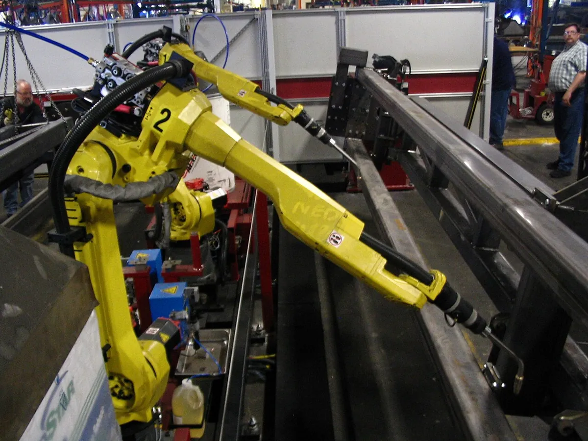
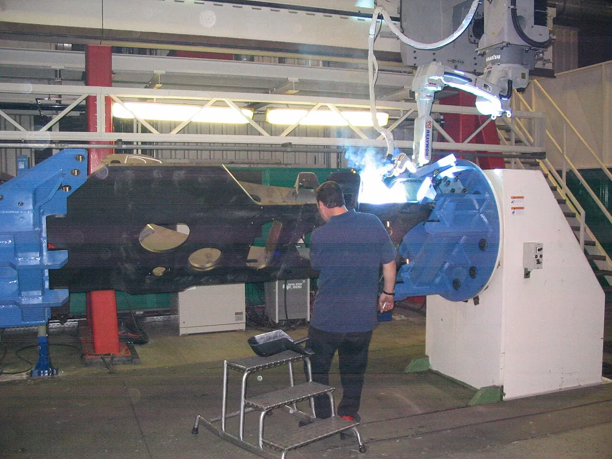
- Welding, gluing and sealing: the tool must follow the seam exactly, so programmers use linear (Cartesian) moves along the seam and joint moves to get there.
- Pick-and-place: fast joint moves in free air, then a short straight-down Cartesian move so the gripper enters the box squarely.
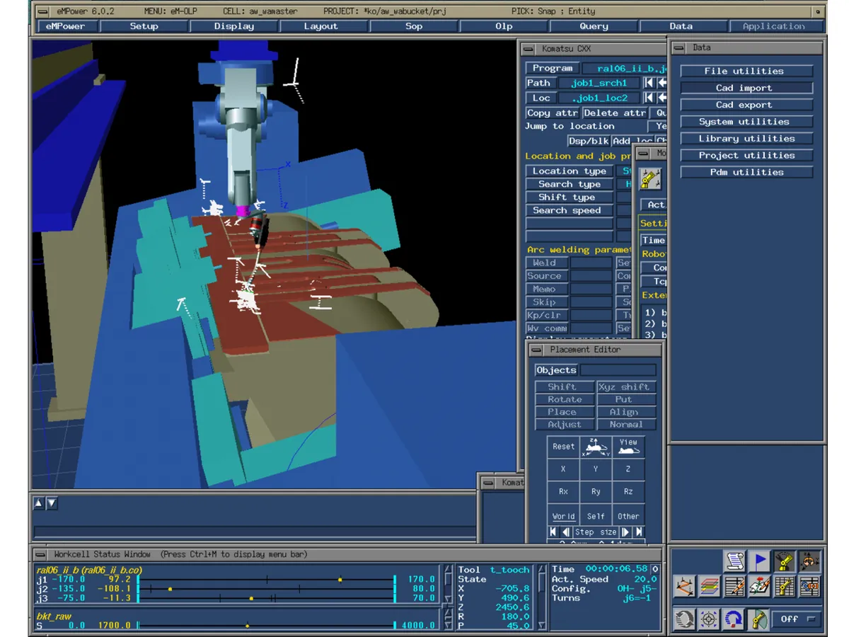
- Offline programming: software simulates the whole program in 3-D before it runs, flagging unreachable points and joint-limit problems on Cartesian moves.
- Robot controllers: ABB’s RAPID language has separate instructions for the two ideas: MoveJ (joint movement) and MoveL (the tool centre point moves along a linear path), plus MoveC for circular paths. The robot works out the path between the two positions itself.
Bench build
Bench build: a pen arm that draws both lines
Build a flat 2-servo arm (shoulder servo fixed to a board, 10 cm link to the elbow servo, 8 cm link to a sketch pen held lightly by a rubber band). pen_arm_two_moves.ino does the same start → goal move two ways: button D2 for joint space, D3 for Cartesian. Put chart paper under it and compare the two lines it draws.
| From | To | Note |
|---|---|---|
| Shoulder servo signal | D9 | — |
| Elbow servo signal | D10 | — |
| Both servos + (red) | Separate 5–6 V supply +, 2 A or more | Two moving servos can draw well over an amp — not the Arduino 5 V pin |
| Both servos − (brown/black) | Supply − | — |
| Supply − | Arduino GND | Common ground |
| Button 1 / Button 2 | D2 ↔ GND / D3 ↔ GND | INPUT_PULLUP |
Mount the horns
Power up once so the servos go to the start pose, then fit the horns so the shoulder link points along +x and the elbow is bent 90°. (In the code the elbow servo’s 45° means a straight elbow — see ELBOW_OFFSET.)
Mark A and B
Mark the start tip (10, 8) cm and goal tip (−4, 16.9) cm on the paper, measured from the shoulder axis. Draw the ideal straight line between them in pencil.
Joint move (D2)
Press D2 with the pen touching the paper. It draws an arc that bulges away from your pencil line — about 3 cm at the widest, as the Python predicted.
Cartesian move (D3)
Lift the pen when asked, let the arm return, put the pen down and press D3. It should follow the pencil line closely. Measure the worst error with a ruler.
Copy the log
The Serial Monitor prints t, x, y, θ₁, θ₂ every 20 ms. Compare a few lines with the Python output.
// pen_arm_two_moves.ino — Stage 9, Lesson 4
// A 2-servo planar "pen arm" (L1 = 10 cm, L2 = 8 cm) draws the SAME start -> goal move twice:
//   button D2: JOINT-space move     (both joints interpolate linearly -> pen draws a curve)
//   button D3: CARTESIAN-space move (pen point interpolates in x, y; IK every step -> straight line)
// Both use a smooth cubic time scaling s(t) over T_MOVE, updated every 20 ms.
// Start: theta = (0°, 90°) -> tip (10.00, 8.00) cm.  Goal: theta = (90°, 30°) -> tip (-4.00, 16.93) cm.
//
// Wiring: shoulder servo signal -> D9, elbow servo signal -> D10.
//         Both servos' + and - -> SEPARATE 5–6 V supply (2 A or more). Supply GND -> Arduino GND.
//         Buttons: D2 -> GND, D3 -> GND (INPUT_PULLUP). Never power servos from Arduino pins.
// Mounting: shoulder servo 0° = arm along +x. Elbow servo: ELBOW_OFFSET (45°) on the servo = straight elbow.

#include <Servo.h>
#include <math.h>

const float L1 = 10.0, L2 = 8.0;
const float T_MOVE = 3.0;               // seconds
const unsigned long DT_MS = 20;
const float ELBOW_OFFSET = 45.0;        // servo angle when theta2 = 0
const float Q0[2] = {0.0, 90.0};
const float Q1[2] = {90.0, 30.0};

Servo shoulder, elbow;

float sCubic(float t) {                 // rest-to-rest cubic, 0..1
  if (t <= 0) return 0;
  if (t >= T_MOVE) return 1;
  float u = t / T_MOVE;
  return 3 * u * u - 2 * u * u * u;
}

void fk(float t1, float t2, float &x, float &y) {
  float a = radians(t1), b = radians(t1 + t2);
  x = L1 * cos(a) + L2 * cos(b);
  y = L1 * sin(a) + L2 * sin(b);
}

bool ik(float x, float y, float &t1, float &t2) {   // elbow-up branch (theta2 >= 0)
  float c2 = (x * x + y * y - L1 * L1 - L2 * L2) / (2 * L1 * L2);
  if (c2 < -1 || c2 > 1) return false;
  float th2 = acos(c2);
  float th1 = atan2(y, x) - atan2(L2 * sin(th2), L1 + L2 * cos(th2));
  t1 = degrees(th1);
  t2 = degrees(th2);
  return true;
}

bool command(float t1, float t2) {      // refuse anything the servos cannot reach
  float a = t1, b = t2 + ELBOW_OFFSET;
  if (a < -0.5 || a > 180.5 || b < -0.5 || b > 180.5) return false;  // 0.5° tolerance for rounding
  a = constrain(a, 0, 180);
  b = constrain(b, 0, 180);
  shoulder.writeMicroseconds(544 + (long)(a * (2400 - 544) / 180.0));
  elbow.writeMicroseconds(544 + (long)(b * (2400 - 544) / 180.0));
  return true;
}

void run(bool cartesian) {
  float x0, y0, x1, y1;
  fk(Q0[0], Q0[1], x0, y0);
  fk(Q1[0], Q1[1], x1, y1);
  Serial.println(cartesian ? F("CARTESIAN move: t,x,y,t1,t2") : F("JOINT move: t,x,y,t1,t2"));
  unsigned long t0 = millis(), next = t0;
  while (true) {
    unsigned long now = millis();
    if (now < next) continue;
    next += DT_MS;
    float t = (now - t0) / 1000.0, s = sCubic(t), t1, t2, x, y;
    if (cartesian) {
      x = x0 + s * (x1 - x0);
      y = y0 + s * (y1 - y0);
      if (!ik(x, y, t1, t2)) { Serial.println(F("STOP: point out of reach")); return; }
    } else {
      t1 = Q0[0] + s * (Q1[0] - Q0[0]);
      t2 = Q0[1] + s * (Q1[1] - Q0[1]);
      fk(t1, t2, x, y);
    }
    if (!command(t1, t2)) { Serial.println(F("STOP: joint limit")); return; }
    Serial.print(t, 2); Serial.print(','); Serial.print(x, 2); Serial.print(',');
    Serial.print(y, 2); Serial.print(','); Serial.print(t1, 1); Serial.print(','); Serial.println(t2, 1);
    if (t >= T_MOVE) break;
  }
  delay(1000);
  // return to start slowly in joint space (pen lifted by hand)
  Serial.println(F("Lift the pen - returning to start in 3 s"));
  delay(3000);
  unsigned long r0 = millis();
  while (millis() - r0 <= (unsigned long)(T_MOVE * 1000)) {
    float s = sCubic((millis() - r0) / 1000.0);
    command(Q1[0] + s * (Q0[0] - Q1[0]), Q1[1] + s * (Q0[1] - Q1[1]));
    delay(DT_MS);
  }
}

void setup() {
  Serial.begin(115200);
  pinMode(2, INPUT_PULLUP);
  pinMode(3, INPUT_PULLUP);
  shoulder.attach(9);
  elbow.attach(10);
  command(Q0[0], Q0[1]);
  Serial.println(F("D2 = joint-space move, D3 = Cartesian move"));
}

void loop() {
  if (digitalRead(2) == LOW) run(false);
  if (digitalRead(3) == LOW) run(true);
}Debugging
Debugging joint and Cartesian moves
| Symptom | Likely cause | Fix |
|---|---|---|
| “Cartesian” line still curved | Servo horn offsets wrong, so real angles ≠ commanded angles | Re-fit horns at the start pose; tune ELBOW_OFFSET |
| Arm flips elbow halfway | IK switched branch (elbow up ↔ down) | Use the same branch for every sample |
| STOP: joint limit at the first step | Rounding gives −0.0001° | Small tolerance (the sketch allows 0.5°) then constrain() |
| Arm whips fast mid-line | Line passes near a singularity (elbow almost straight or folded) | Move the line away from the base / workspace edge, or use a joint move there |
| Servos jitter and Arduino resets | Servos on Arduino power | Separate supply + common ground |
Think
Think about it
Think
Your arm must take a sweet from a tray and drop it into a jar 40 cm away, then push a peg 3 cm straight down into a hole. Which parts of the job would you plan in joint space, and which in Cartesian space? Why?
Experiment
Try it in the lab
About 35 minutes with the Python file and the browser labs; the pen arm is optional but very convincing.
Experiment
Curve or straight?
You will need
- `joint_vs_cartesian.py` and Python 3
- Graph paper
- Joint-space interpolator and Cartesian trajectory planner (in your browser)
- Optional: Arduino UNO, two hobby servos, separate 5–6 V 2 A supply, 2 buttons, card links, sketch pen, chart paper
Steps
- Run the program. On graph paper, plot the tip points of Move 1 and draw the straight line from start to goal. Shade the gap.
- Change the goal to θ = (30°, 60°) (a small move). Is the tip curve still noticeably bent? What does that tell you about short moves?
- In Move 2, print joint speeds for every sample (remove the `k % 4` filter). Plot the fastest joint’s speed against s.
- Change Move 3’s line to y = 5 cm and then y = 1 cm. What happens to the peak joint speed, and what happens at y = 1 cm?
- In the Cartesian planner, place a line far from the base and one close to the base. Compare the joint curves.
- Optional: draw both lines with the pen arm and measure the largest gap from your pencil line for each.
Interactive · Cartesian trajectory planner (2R educational · Stage 8 IK)
Interpolate a straight line in task space, then call Stage 8 ik2R each sample. Labeled simplified — not industrial 6DOF.
- EE (x,y)
- 100.0, 40.0
- Joints (°)
- -18.4, 96.4
- Path health (samples)
- unreachable=0 · joint-limit≈0 · singular=0
Joint-space lines give calm joints and a curved tip; Cartesian lines give a straight tip and uneven joints. The closer a Cartesian line comes to a singularity, the faster some joint has to move; inside the hole near the base, IK has no answer at all.
Knowledge check
Check your understanding
Knowledge check
1. Each joint moves linearly from its start angle to its goal angle. The tool path is usually…
2. To make the tool move in a straight line, you…
3. A Cartesian line passes close to a singularity. The likely result is…
4. Both ends of a Cartesian line are reachable. Is every point in between reachable?
5. Which move type is the natural choice for a fast move through free air?
6. In `joint_vs_cartesian.py`, how far did the tip stray from the straight line during the joint move?
7. Why must a Cartesian planner stay on one IK branch?
Mini assignment
Hands-on assignment
Mini assignment
Choose the right move
Plan a small real job with your arm, choosing joint or Cartesian moves for each part, and prove your choices with numbers.
Deliverables
- Describe a 3-step job (e.g. go above a cup, go straight down 4 cm, go to a bin). Mark each step as joint or Cartesian and say why.
- For one Cartesian step, run it through `joint_vs_cartesian.py` (change P_START/P_GOAL) and report the peak joint speed and any unreachable samples.
- For one joint step, report how far the tip strays from the straight line.
- A neat top-view sketch showing both tip paths over the reachable ring of the arm (outer radius 18 cm, inner 2 cm).
- Optional: a photo of the chart paper with both pen-arm lines and your measured errors.
Do this, step by step
- Run
python3 joint_vs_cartesian.pyand note the largest tip error of the joint move and the peak joint speed of the Cartesian move. - Change the start and goal points to your own two points inside the reachable ring (between 2 cm and 18 cm from the shoulder). Re-run.
- Pick a goal very close to the outer edge (about 17.5 cm). Watch how the peak joint speed of the Cartesian move changes.
- In the Cartesian trajectory planner, draw one straight-line move and one joint move between the same points and sketch both tip paths.
- Optional bench: run
pen_arm_two_moves.inoon chart paper and measure the biggest gap between the joint-move line and a ruler line.
Stuck? Hints, one at a time
- A joint move interpolates angles, so the tip usually curves; a Cartesian move interpolates the tip, so IK runs at every sample.
- Near the edge of the workspace the arm is almost straight — tiny tip steps need big joint changes.
- If a sample is unreachable, the straight line has left the ring; move the points or add a waypoint.
Challenges (pick by level)
- 🟢 Easy: Write three jobs at home or in a shop that need a straight tool line and three that don’t.
- 🟢 Easy: Explain to a friend, with your arm and a chalk, why steady joint motion draws an arc.
- 🟡 Medium: Add a joint-limit check (0°–180° shoulder, 0°–150° elbow) to Move 2 and print which samples fail.
- 🟠 Hard-ish: Make Move 3 safe automatically: if any sample’s joint speed exceeds 150°/s, stretch T until it doesn’t, and print the new T.
- 🔴 Hard: Write a “hybrid” planner: joint move to a point 3 cm above the goal, then a Cartesian move straight down. Print both segments.
- ⚫ Research: Read the MoveJ / MoveL / MoveC part of the ABB RAPID motion summary (in Sources) and compare it with this lesson’s table.
Next step
Real jobs are not one move but many, joined together. In Lesson 5 — Waypoints & Motion Segments you will break a task into waypoints and segments, and decide what happens at each corner.
Look back: Stage 8: Inverse Kinematics — Concept. Next: Lesson 5: Waypoints & Motion Segments. Related: Stage 8 — Kinematics & IK.
Sources
- Modern Robotics (Lynch & Park) — book home page and free PDF — §9.2.1: straight lines in joint space vs task space; singularities give very large joint velocities; non-convex reachable space; Figure 9.1 (2R arm with joint limits).
- Modern Robotics video — 9.1 and 9.2 Point-to-Point Trajectories — companion lecture.
- ABB RAPID summary — Motion (RobotStudio course page) — MoveJ = joint movement, MoveL = TCP along a linear path, MoveC = circular path; acceleration and behaviour near singular points are settable motion characteristics.
- Wikipedia — Linear interpolation — the straight-line formula used in both spaces.
- Photos and screenshot: Wikimedia Commons (credits under each image).
Self-attested for now — keep artifacts in your lab notebook.
Complete
Today's goal
0 of 1 done today
Mark this lesson complete when you have worked the experiment, knowledge check, and assignment (even roughly).