
Kinematics & Inverse Kinematics · Lesson 11
Robot Workspace
Est. 60–80 min
Why
Why this lesson matters
A robot’s workspace is the set of places its end-effector can actually reach. It depends on link lengths, joint limits and obstacles such as the table and the robot’s own base. Before you write IK (Lessons 12–14) you must know whether a target is inside the workspace at all — otherwise no solver in the world can help.
By the end of this lesson you will be able to: explain reachable vs dexterous workspace; compute the reach ring |L2 − L3| … L2 + L3 of a two-link chain; map your arm’s side-view workspace by sweeping its joints; see how joint limits, the table and the base cut the workspace; and decide quickly whether (and from which direction) a target can be reached.
Concept
Reachable and dexterous workspace
Two kinds of workspace
| Name | Meaning | Everyday picture |
|---|---|---|
| Reachable workspace | Every point the tip can reach with at least one orientation | Every spot on the wall you can touch with a fingertip |
| Dexterous workspace | Points the tip can reach with every orientation you need | Spots where you can touch with your palm flat, sideways or upside-down — a much smaller area |
*Modern Robotics* defines the workspace as the configurations the end-effector can reach, decided by the robot’s structure, and the task space as what the job needs. The user chooses whether orientation matters. For picking sweets from above you need ‘approach straight down’, so your useful workspace is the set of points reachable *with that orientation*.
The reach ring of two links
Take the shoulder–elbow pair (L2, L3) with free joints. Fully stretched, the wrist is L2 + L3 from the shoulder. Fully folded, it is |L2 − L3|. Anything in between can be reached, so the wrist centre lives in a ring (annulus): |L2 − L3| ≤ distance ≤ L2 + L3. For the example arm: 0.7 cm … 20.3 cm from the shoulder axis.
What shrinks the workspace
- Joint limits: hobby servos turn about 180°; a joint that cannot fold backwards removes whole regions.
- The table: nothing below z = 0.
- The robot’s own body: the base housing and the links themselves.
- Required orientation: demanding ‘straight down’ or ‘level’ approach removes points near the edge of reach.
- Payload and accuracy: industrial datasheets note that accuracy and repeatability change across the working envelope.
Visual
Visualise it: the reach ring
A two-link planar arm: the reachable region is a ring between |L₁ − L₂| and L₁ + L₂. Joint limits cut pieces out of it.
Interactive · Workspace & reach demo
rₘᵢₙ / rₘₐₓ
20 / 140
Tip radius
127.2
Dashed circles = theoretical annulus without joint limits. Dots = reachable samples under ±limit. Stage 6 will map this idea onto a real 6-axis kit — without reteaching it here.
Code lab
Code lab: workspace.py
workspace.py sweeps J2, J3 and J4 of the example arm in 5° steps inside example joint limits, throws away tip points below the table or inside the base housing, and keeps every 1 cm cell of the side view the tip can reach. Then, for chosen approach angles, it checks each cell exactly: put the wrist centre L4 back along the approach and solve the two-link problem inside the joint limits. It prints the reach numbers, an ASCII map, and checks five targets.
# workspace.py - map the side-view workspace of the example arm.
# Reachable workspace: every tip point the arm can reach with SOME orientation (found by sweeping joints).
# Dexterous ("all-approach") workspace: points it can reach BOTH 45 deg down AND straight down
# (checked exactly: put the wrist centre L4 back along each approach and solve the 2-link problem).
# Side view only (r = distance from base axis, z = height); J1 then swings this around.
# EXAMPLE sizes in cm and EXAMPLE joint limits - use your own arm's numbers.
import math

D1, L2, L3, L4 = 9.0, 10.5, 9.8, 14.0
LIM2 = (0, 180)      # shoulder: horizontal forward .. horizontal backward
LIM3 = (-150, 0)     # elbow: folds down only
LIM4 = (-120, 90)    # wrist pitch
STEP = 5             # degrees per sample
BASE_R = 5.0         # the base/shoulder housing: a 5 cm radius column up to shoulder height


def allowed(r, z):
    return z >= 0 and not (abs(r) < BASE_R and z < D1)   # above the table, outside the base housing


def reach_with(r, z, phi):
    """Can the tip be at (r, z) with approach angle phi (deg; 0 = level, -90 = straight down)?"""
    if not allowed(r, z):
        return False
    wr = r - L4 * math.cos(math.radians(phi))
    wz = z - L4 * math.sin(math.radians(phi)) - D1      # wrist centre, relative to the shoulder
    d = math.hypot(wr, wz)
    if d > L2 + L3 or d < abs(L2 - L3):
        return False
    beta = math.acos((L2 * L2 + L3 * L3 - d * d) / (2 * L2 * L3))
    alpha = math.acos(max(-1, min(1, (d * d + L2 * L2 - L3 * L3) / (2 * L2 * d))))
    gamma = math.atan2(wz, wr)
    for j2, j3 in ((gamma - alpha, math.pi - beta), (gamma + alpha, beta - math.pi)):
        j2, j3 = math.degrees(j2), math.degrees(j3)
        j4 = phi - j2 - j3
        if LIM2[0] <= j2 <= LIM2[1] and LIM3[0] <= j3 <= LIM3[1] and LIM4[0] <= j4 <= LIM4[1]:
            return True
    return False


# 1) reachable workspace: sweep the joints, keep allowed tip points on a 1 cm grid
cells = set()
for j2 in range(LIM2[0], LIM2[1] + 1, STEP):
    for j3 in range(LIM3[0], LIM3[1] + 1, STEP):
        for j4 in range(LIM4[0], LIM4[1] + 1, STEP):
            a, b, c = (math.radians(v) for v in (j2, j2 + j3, j2 + j3 + j4))
            r = L2 * math.cos(a) + L3 * math.cos(b) + L4 * math.cos(c)
            z = D1 + L2 * math.sin(a) + L3 * math.sin(b) + L4 * math.sin(c)
            if allowed(r, z):
                cells.add((round(r), round(z)))

APPROACHES = (0, -45, -90)                          # level, 45 deg down, straight down
PICK = (-45, -90)                                   # the approaches a picking job needs
dex = {c for c in cells if all(reach_with(c[0], c[1], p) for p in PICK)}
print(f"Example arm D1 {D1}, L2 {L2}, L3 {L3}, L4 {L4} cm; limits J2 {LIM2}, J3 {LIM3}, J4 {LIM4}")
print(f"Reachable side-view cells (1 cm): {len(cells)}   pick-ready cells (45 down AND straight down): {len(dex)}")
fwd = [c for c in cells if c[0] >= 0]
print(f"Max forward reach at any height: r = {max(c[0] for c in fwd)} cm   max height: z = {max(c[1] for c in cells)} cm")
table = [c[0] for c in fwd if c[1] == 0]
print(f"On the table (z = 0) the tip reaches r = {min(table)} .. {max(table)} cm")
down = [r for r in range(0, 40) if reach_with(r, 0, -90)]
print(f"On the table, straight-down (from above) picks work for r = {min(down)} .. {max(down)} cm")
print(f"Wrist-centre ring around the shoulder: {abs(L2 - L3):.1f} .. {L2 + L3:.1f} cm (|L2 - L3| .. L2 + L3)")

# 2) ASCII side view: '#' pick-ready, '+' reachable, '.' not reachable; S = shoulder axis
print("\nSide view, forward half (r 0..44 cm, z 0..44 cm), 2 cm per character")
for z in range(44, -1, -2):
    row = ""
    for r in range(0, 45, 2):
        row += "S" if (r, z) == (0, 8) else "#" if (r, z) in dex else "+" if (r, z) in cells else "."
    print(f"{z:3d} |{row}")
print("    +" + "-" * 23)
print("     r=0                 r=44")

# 3) is a target reachable, and from which approach angles?
print("\nTarget checks (r, z) cm -> which approaches work (level 0, 45 down -45, straight down -90)")
for target in ((20, 5), (30, 9), (8, 2), (36, 4), (15, 30)):
    ok = [p for p in APPROACHES if reach_with(*target, p)]
    status = "NOT reachable" if target not in cells else f"reachable; of the three approaches: {ok if ok else 'none (other angles only)'}"
    print(f"  {str(target):<9} {status}")
Output (run with python3 workspace.py)
Example arm D1 9.0, L2 10.5, L3 9.8, L4 14.0 cm; limits J2 (0, 180), J3 (-150, 0), J4 (-120, 90)
Reachable side-view cells (1 cm): 2143   pick-ready cells (45 down AND straight down): 85
Max forward reach at any height: r = 34 cm   max height: z = 43 cm
On the table (z = 0) the tip reaches r = 5 .. 33 cm
On the table, straight-down (from above) picks work for r = 5 .. 19 cm
Wrist-centre ring around the shoulder: 0.7 .. 20.3 cm (|L2 - L3| .. L2 + L3)

Side view, forward half (r 0..44 cm, z 0..44 cm), 2 cm per character
 44 |.......................
 42 |++++++.................
 40 |+++++++++..............
 38 |++++++++++.............
 36 |++++++++++++...........
 34 |+++++++++++++..........
 32 |++++++++++++++.........
 30 |++++++++++++++.........
 28 |+++++++++++++++........
 26 |++++++++++++++++.......
 24 |++++++++++++++++.......
 22 |+++++++++++++++++......
 20 |+++++++++++++++++......
 18 |+++++++++++++++++......
 16 |++++++++++++++++++.....
 14 |.+++++++++++++++++.....
 12 |.+++++++++++++++++.....
 10 |.++###++++++++++++.....
  8 |S..#####++++++++++.....
  6 |...+#####+++++++++.....
  4 |...+++####++++++++.....
  2 |...+++++##+++++++......
  0 |...+++++##+++++++......
    +-----------------------
     r=0                 r=44

Target checks (r, z) cm -> which approaches work (level 0, 45 down -45, straight down -90)
  (20, 5)   reachable; of the three approaches: [-45]
  (30, 9)   reachable; of the three approaches: [0]
  (8, 2)    reachable; of the three approaches: [-90]
  (36, 4)   NOT reachable
(15, 30) reachable; of the three approaches: none (other angles only)Try it: change L₁ and L₂ and watch the reach ring. Make the links equal — what happens to the hole in the middle? Then lower the joint-limit slider and watch the reachable dots shrink inside the dashed ring.
Interactive · Workspace & reach demo
rₘᵢₙ / rₘₐₓ
20 / 140
Tip radius
127.2
Dashed circles = theoretical annulus without joint limits. Dots = reachable samples under ±limit. Stage 6 will map this idea onto a real 6-axis kit — without reteaching it here.
Real world
Workspaces in the real world
- Choosing a robot: the ‘working envelope’ — the region of space a robot can reach — is one of the first numbers on an industrial robot’s datasheet.
- Cell layout: parts, conveyors and fixtures are placed inside the comfortable part of the workspace; guards are placed outside the full envelope.
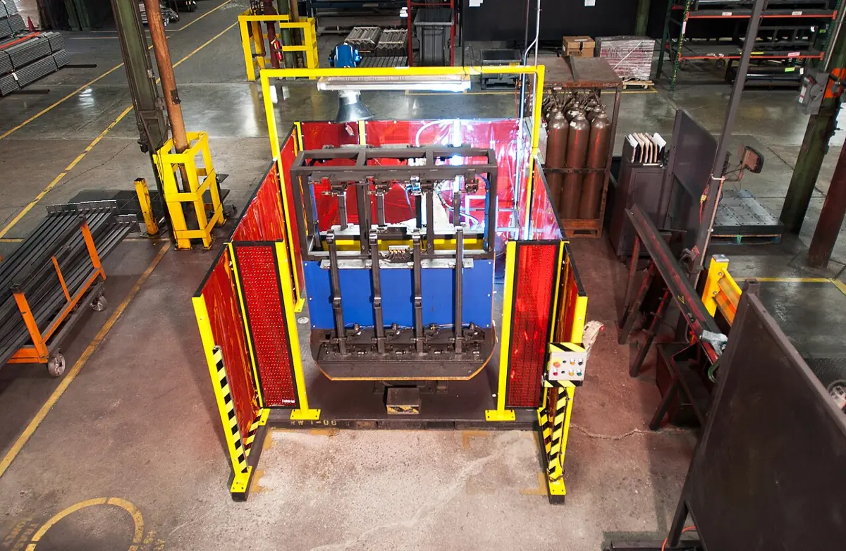
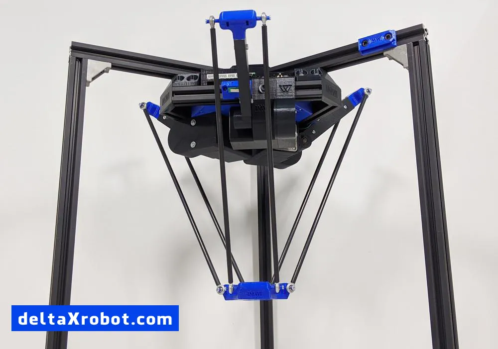
- Different structures, different shapes: articulated arms give roughly spherical regions, SCARA arms a flat ring, delta robots a squat region under the frame.
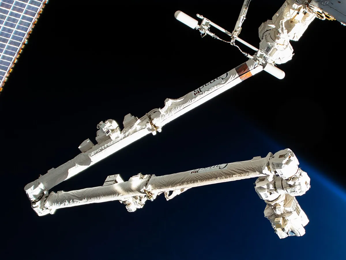
- Space: the International Space Station’s Canadarm2 is about 17.6 m (57.7 ft) long, giving it a huge workspace around the station.
Bench build
Bench build: a reach scout at the base
Before your arm tries to pick something, it is useful to know if the object is even in reach. reach_scout.ino uses an HC-SR04 ultrasonic sensor at the base, looking forward along the table, and sorts the nearest object into the zones from workspace.py: too close, reachable from above, tilted approach only, or out of reach. A green or red LED shows the verdict.
Wire it
HC-SR04: VCC → 5 V, GND → GND, TRIG → 9, ECHO → 10. Green LED with 220 Ω on pin 6, red LED with 220 Ω on pin 7.
Mount it
At the base, a few cm above the table, facing forward. Measure the sensor face to the base axis and set SENSOR_TO_AXIS_CM.
Put in your numbers
Run
workspace.pywith your arm’s sizes and limits and copy the table-level zone limits into the sketch.Test
Slide a box towards and away from the base and watch the zones change. Check each boundary with a ruler.
// reach_scout.ino - "can my arm reach that?" An HC-SR04 at the arm's base looks forward along
// the table and sorts the nearest object into workspace zones from workspace.py.
// Zones (EXAMPLE arm, on the table, measured from the base axis - recompute for YOUR arm):
//   r < 5 cm        inside the base housing / too close
//   5 .. 19 cm      reachable straight from above (best for picking)
//   19 .. 33 cm     reachable only with a tilted approach
//   r > 33 cm       out of reach - move the object or the robot
// Wiring: VCC -> 5 V, GND -> GND, TRIG -> pin 9, ECHO -> pin 10. Green LED + 220 ohm on pin 6,
// red LED + 220 ohm on pin 7. No motors in this build.
// If you mount it on the real arm: the arm's servos stay on their own 5-6 V supply with a common
// ground - never powered from the Arduino 5 V pin.
const int TRIG = 9, ECHO = 10, LED_OK = 6, LED_NO = 7;
const float SENSOR_TO_AXIS_CM = 3.0;     // sensor face is 3 cm in front of the base axis - measure
const float BASE_R = 5, DOWN_MAX = 19, REACH_MAX = 33;

float distanceCm() {
  digitalWrite(TRIG, LOW); delayMicroseconds(2);
  digitalWrite(TRIG, HIGH); delayMicroseconds(10);
  digitalWrite(TRIG, LOW);
  unsigned long us = pulseIn(ECHO, HIGH, 30000UL);   // time-out after 30 ms
  if (us == 0) return -1;                            // no echo
  return us * 0.0343 / 2.0;                          // speed of sound ~343 m/s, there and back
}

void setup() {
  pinMode(TRIG, OUTPUT); pinMode(ECHO, INPUT);
  pinMode(LED_OK, OUTPUT); pinMode(LED_NO, OUTPUT);
  Serial.begin(115200);
}

void loop() {
  float d = distanceCm();
  if (d < 0) { Serial.println(F("no echo")); delay(300); return; }
  float r = d + SENSOR_TO_AXIS_CM;                   // distance from the base axis
  const __FlashStringHelper *zone;
  bool ok = false;
  if (r < BASE_R) zone = F("too close / inside base");
  else if (r <= DOWN_MAX) { zone = F("reachable from above"); ok = true; }
  else if (r <= REACH_MAX) { zone = F("reachable, tilted approach only"); ok = true; }
  else zone = F("OUT OF REACH");
  digitalWrite(LED_OK, ok); digitalWrite(LED_NO, !ok);
  Serial.print(F("r = ")); Serial.print(r, 1); Serial.print(F(" cm  -> ")); Serial.println(zone);
  delay(300);
}
Debugging
Debugging workspace maps
| Symptom | Likely cause | Fix |
|---|---|---|
| Map shows points below the table | No z ≥ 0 check | Throw away tip points with z < 0 (and elbow points too, as an extra) |
| Arm hits its own base at ‘reachable’ points | Base housing not modelled | Exclude a column of radius BASE_R up to shoulder height |
| Map has holes/stripes | Sweep step too coarse | Use smaller steps (2–3°) or a finer grid |
| Real arm can’t reach a mapped point | Real joint limits narrower than in the code | Measure each servo’s real end stops and update LIM2–LIM4 |
| Reach is fine but the pick fails | Target needs an orientation not available there | Check which of the test approaches work for that cell |
| Scout says ‘out of reach’ for a near object | Sensor sees something else (a wall, a cable) | Aim the sensor lower/clear the view; check the raw distance |
Think
Think about it
Think
Ishaan says, “If I make both links longer, the arm can reach everything it reached before, plus more.” Is that always true?
Experiment
Try it in the lab
About 45 minutes with workspace.py, a ruler and chalk, and optionally your Stage 6 arm and the reach scout.
Experiment
Map your arm’s workspace
You will need
- `workspace.py` and Python 3
- Ruler, chalk or masking tape
- Optional: Stage 6 arm, Arduino UNO, HC-SR04, two LEDs and 220 Ω resistors
Steps
- Run `workspace.py` and find the straight-down pick band on the table.
- Change J3’s limit to (−90, 0). Run again: how much smaller is the map?
- Put in your own arm’s sizes and real joint limits (measure each servo’s end stops).
- Mark the straight-down pick band on your table with tape, as an arc around the base.
- Test three points inside and one outside the band with your arm (move slowly, servo supply switch in reach).
- In the interactive, find the link lengths that remove the inner hole completely.
Interactive · Workspace & reach demo
rₘᵢₙ / rₘₐₓ
20 / 140
Tip radius
127.2
Dashed circles = theoretical annulus without joint limits. Dots = reachable samples under ±limit. Stage 6 will map this idea onto a real 6-axis kit — without reteaching it here.
The full reach is a big number, but the useful, ‘any approach you like’ region is a small band. Joint limits, the table and the base all eat into it. Knowing the band tells you where to put the work.
Knowledge check
Check your understanding
Knowledge check
1. The reachable workspace is…
2. Compared with the reachable workspace, the dexterous workspace is…
3. Two links of 10.5 and 9.8 cm (free joints). The wrist can be from the shoulder at distances…
4. In workspace.py, a target at (36, 4) cm is…
5. Which of these does NOT change a robot’s workspace?
6. Why does the straight-down pick band end before the maximum reach?
7. Guards and fences around an industrial robot are placed using…
Mini assignment
Hands-on assignment
Mini assignment
Workspace map for your arm
Make a workspace map of your Stage 6 arm (or the example arm) that someone could use to lay out a pick-and-place table.
Deliverables
- Your arm’s sizes and measured joint limits.
- The ASCII (or plotted) side-view map from `workspace.py` with your numbers.
- A top-view sketch: the straight-down pick band as an arc around the base (J1 range).
- Three targets you chose, each marked reachable/not and from which approach.
- A layout proposal: where to put the tray and the boxes, with reasons.
Do this, step by step
- Put your arm’s lengths and joint limits (
LIM2,LIM3,LIM4) intoworkspace.pyand run it. Save the side-view map. - Change
STEPfrom 5 to 2 and compare the maps. Write whether the outline changed. - Draw a top view: the straight-down pick band as an arc around the base, using your J1 range.
- Choose three targets on your table and mark each as reachable or not, and with which approach (level, 45° or straight down).
- Propose a layout: where the tray and boxes go and why, using your map as evidence.
Stuck? Hints, one at a time
- A point is reachable if at least one approach angle gives an IK answer inside all limits.
- The base column (BASE_R) removes points the arm would have to reach through itself.
- Keep the tray inside the straight-down pick band; the edge of the map is near a singular pose.
Challenges (pick by level)
- 🟢 Easy: Compute the reach ring for links 12 cm and 8 cm by hand.
- 🟢 Easy: Change STEP to 2° and see whether the map changes.
- 🟡 Medium: Plot the map with matplotlib, colouring each cell by how many approach angles reach it.
- 🟠 Hard-ish: Add an obstacle (a 10 cm-tall box from r = 12 to 16 cm) and remove points where any link would pass through it.
- 🔴 Hard: Extend to 3D: sweep J1 too and estimate the reachable volume above the table in cm³.
- ⚫ Research: Compare the published working envelope drawings of an articulated arm, a SCARA and a delta robot.
Next step
You know where the arm *can* go. In Lesson 12 — Inverse Kinematics: Concept you turn the question around: given a target inside the workspace, which joint angles put the gripper there?
Look back: Lesson 10: End-Effector Pose Calculation. Next: Lesson 12: Inverse Kinematics — Concept. Related: Stage 9 — Trajectory Planning and Stage 13 — Perception, Planning & Manipulation.
Sources
- Modern Robotics — K. M. Lynch & F. C. Park (book home page, free preprint) — Section 2.5 Task Space and Workspace: the workspace is what the end-effector can reach, driven by the robot’s structure; the task space is driven by the task.
- Wikipedia — Industrial robot — ‘working envelope’ (the region of space a robot can reach); accuracy and repeatability vary within the envelope.
- Wikipedia — Envelope (motion) — an envelope is the solid of all positions an object may occupy during its motion.
- Canadarm2 length (57.7 ft) from the NASA photo description on Wikimedia Commons (credit under the image).
- Photos: Wikimedia Commons (credits under each image).
Self-attested for now — keep artifacts in your lab notebook.
Complete
Today's goal
0 of 1 done today
Mark this lesson complete when you have worked the experiment, knowledge check, and assignment (even roughly).