
Control Systems & PID · Lesson 13
Robot Joint Control Architecture
Est. 60–75 min
Why
Why a joint controller is more than one PID
So far you have built every piece separately: PID (Lessons 5–8), metrics and tuning (9–10), limits (11) and filters (12). A real joint controller puts them in layers, each with one job. *Modern Robotics* (Sec. 11.4) adds one more important idea: a robot controller usually combines feedforward (what the model says the move needs) with feedback (correcting what the model got wrong).
By the end of this lesson you will be able to: draw the layers of a joint controller (planner, controller, limits, driver, sensor); explain feedforward vs feedback with numbers; compare feedback only, feedforward only and both on a planned move; explain when per-joint (decentralised) control is good enough and when it isn’t (Modern Robotics); and run a layered joint controller on the motor bench.
Concept
The layers of a joint controller
The five layers
| Layer | Job | Where you met it |
|---|---|---|
| 1. Planner | Turns “go to 90°” into a smooth path of angle (and speed) vs time | This lesson (cubic path) |
| 2. Controller | Feedforward + PID on the path error | Lessons 5–8, this lesson |
| 3. Limits | Output, integral, slew, position, stall | Lesson 11 |
| 4. Driver | Turns the command into motor current (H-bridge, separate supply) | Lesson 7 |
| 5. Sensor + filter | Measures the joint; smooths the speed estimate | Lessons 3, 12 |
The layers run in a fixed-rate loop (Lesson 4). Each one is simple on its own, and you can test it on its own — that is the main reason to separate them.
Feedforward + feedback
Feedforward uses a model to calculate the torque a planned move should need (inertia × acceleration + friction + gravity). Feedback (PID) corrects the difference between the plan and the measurement. *Modern Robotics* shows that feedforward alone suffers from model errors, feedback alone must wait for an error before acting, and together — the *computed torque* controller — they track better than either alone. It also notes that when the full model is too hard to compute at servo rate, a simpler approximation is PID plus gravity compensation.
| Controller | RMS error | Max error | Effort | Final |
|---|---|---|---|---|
| Feedback only (PID) | 10.47° | 20.72° | 0.504 | 89.23° |
| Feedforward only, exact model | 0.18° | 0.25° | 0.585 | 90.25° |
| Feedforward only, model 20 % off | 16.94° | 22.08° | 0.843 | 112.08° |
| FF + FB, exact model | 0.03° | 0.06° | 0.584 | 90.00° |
| FF + FB, model 20 % off | 2.12° | 4.20° | 0.674 | 90.15° |
Feedback alone lags the plan by up to 20°: it can only push once an error exists. Feedforward with a perfect model is nearly perfect — but a 20 % wrong model ends 22° off. Put them together and even the wrong model tracks within about 4°. That is why real joint controllers use both.
One joint at a time — or all together?
*Modern Robotics* calls per-joint control decentralised control: each joint has its own controller and ignores the others. It works well when the joints hardly affect each other — for example highly geared robots without big gravity effects. When gravity and coupling between joints are significant, decentralised control may not be good enough, and a centralised controller that uses a model of the whole arm is needed. For your 6-DOF arm with hobby servos and gearboxes, start with per-joint control and add gravity compensation where it helps.
Visual
Visualise it: one joint, all the layers
Command the joint and watch the **plan, the controller and the motor** work together. Try a big jump and a small move — which layer limits the motion?
Interactive · Robot joint controller · Capstone target 90°
θ now
0.0°
t
0.0s
Rise
1.75s
Overshoot
18.2%
|SSE|
1.94°
Capstone gate: |SSE| < 3°, overshoot < 25%, rise < 3.5s under load — PASS
Code lab
Code lab: feedforward, feedback and both
joint_architecture.py plans a smooth 0° → 90° move in 1 s (a cubic path) and runs five controllers: feedback only, feedforward only (exact and 20 % wrong model) and feedforward + feedback. It prints tracking error and control effort (∫τ² dt). Run it with python3 joint_architecture.py.
# joint_architecture.py - feedforward, feedback, and both, on a planned joint move.
# Same joint as Lessons 5-12. The arm should follow a smooth planned move 0 -> 90 deg in 1 s.
# Idea from Modern Robotics Sec. 11.4: feedforward is used together with feedback.
# We print tracking error and control effort (integral of torque^2).
import math

J, B, LOAD, TAU_MAX = 0.002, 0.004, 0.05, 4.0
DT, T_END, T_MOVE = 0.001, 2.0, 1.0
KP, KI, KD = 0.04, 0.002, 0.008


def plan(t):
    """Cubic time scaling: smooth start and stop. Returns angle, speed, acceleration."""
    s = min(t / T_MOVE, 1.0)
    pos = 90.0 * (3 * s**2 - 2 * s**3)
    vel = 90.0 * (6 * s - 6 * s**2) / T_MOVE if t < T_MOVE else 0.0
    acc = 90.0 * (6 - 12 * s) / T_MOVE**2 if t < T_MOVE else 0.0
    return pos, vel, acc


def run(use_ff, use_fb, model_error=0.0):
    # the feedforward uses a MODEL of the joint, which may be wrong by model_error (e.g. 0.2 = 20 %)
    Jm, Bm, Lm = (J * (1 + model_error), B * (1 + model_error), LOAD * (1 + model_error))
    angle = speed = integral = 0.0
    sq_err = effort = max_err = 0.0
    n = int(T_END / DT)
    for i in range(n):
        t = i * DT
        pd, vd, ad = plan(t)
        e = pd - angle
        integral += e * DT
        tau = 0.0
        if use_ff:
            tau += Jm * ad + Bm * vd + Lm                   # what the model says the move needs
        if use_fb:
            tau += KP * e + KI * integral + KD * (vd - speed)  # correct what the model got wrong
        tau = max(-TAU_MAX, min(TAU_MAX, tau))
        speed += (tau - B * speed - LOAD) / J * DT
        angle += speed * DT
        sq_err += e * e * DT
        effort += tau * tau * DT
        max_err = max(max_err, abs(e))
    return math.sqrt(sq_err / T_END), max_err, effort, angle


print("Planned move 0 -> 90 deg in 1 s (cubic). PID Kp 0.04, Ki 0.002, Kd 0.008\n")
print(f"{'controller':>26} {'RMS error':>10} {'max error':>10} {'effort':>8} {'final':>8}")
for name, ff, fb, err in (("feedback only (PID)", False, True, 0.0),
                          ("feedforward only, exact", True, False, 0.0),
                          ("feedforward only, 20% off", True, False, 0.2),
                          ("ff + fb, exact model", True, True, 0.0),
                          ("ff + fb, 20% model error", True, True, 0.2)):
    rms, mx, eff, fin = run(ff, fb, err)
    print(f"{name:>26} {rms:>9.2f}° {mx:>9.2f}° {eff:>8.3f} {fin:>7.2f}°")
print("\nFeedforward does most of the work when the model is good; feedback fixes what the")
print("model gets wrong. With a 20 % wrong model, ff + fb still tracks far better than either alone.")
Output (run with python3 joint_architecture.py)
Planned move 0 -> 90 deg in 1 s (cubic). PID Kp 0.04, Ki 0.002, Kd 0.008

                controller  RMS error  max error   effort    final
       feedback only (PID)     10.47°     20.72°    0.504   89.23°
   feedforward only, exact      0.18°      0.25°    0.585   90.25°
 feedforward only, 20% off     16.94°     22.08°    0.843  112.08°
      ff + fb, exact model      0.03°      0.06°    0.584   90.00°
  ff + fb, 20% model error      2.12°      4.20°    0.674   90.15°

Feedforward does most of the work when the model is good; feedback fixes what the
model gets wrong. With a 20 % wrong model, ff + fb still tracks far better than either alone.Try it: command the joint to a new angle and watch the path, the controller and the motor work together. Change one layer at a time.
Interactive · Robot joint controller · Capstone target 90°
θ now
0.0°
t
0.0s
Rise
1.75s
Overshoot
18.2%
|SSE|
1.94°
Capstone gate: |SSE| < 3°, overshoot < 25%, rise < 3.5s under load — PASS
Real world
Joint control in real robots
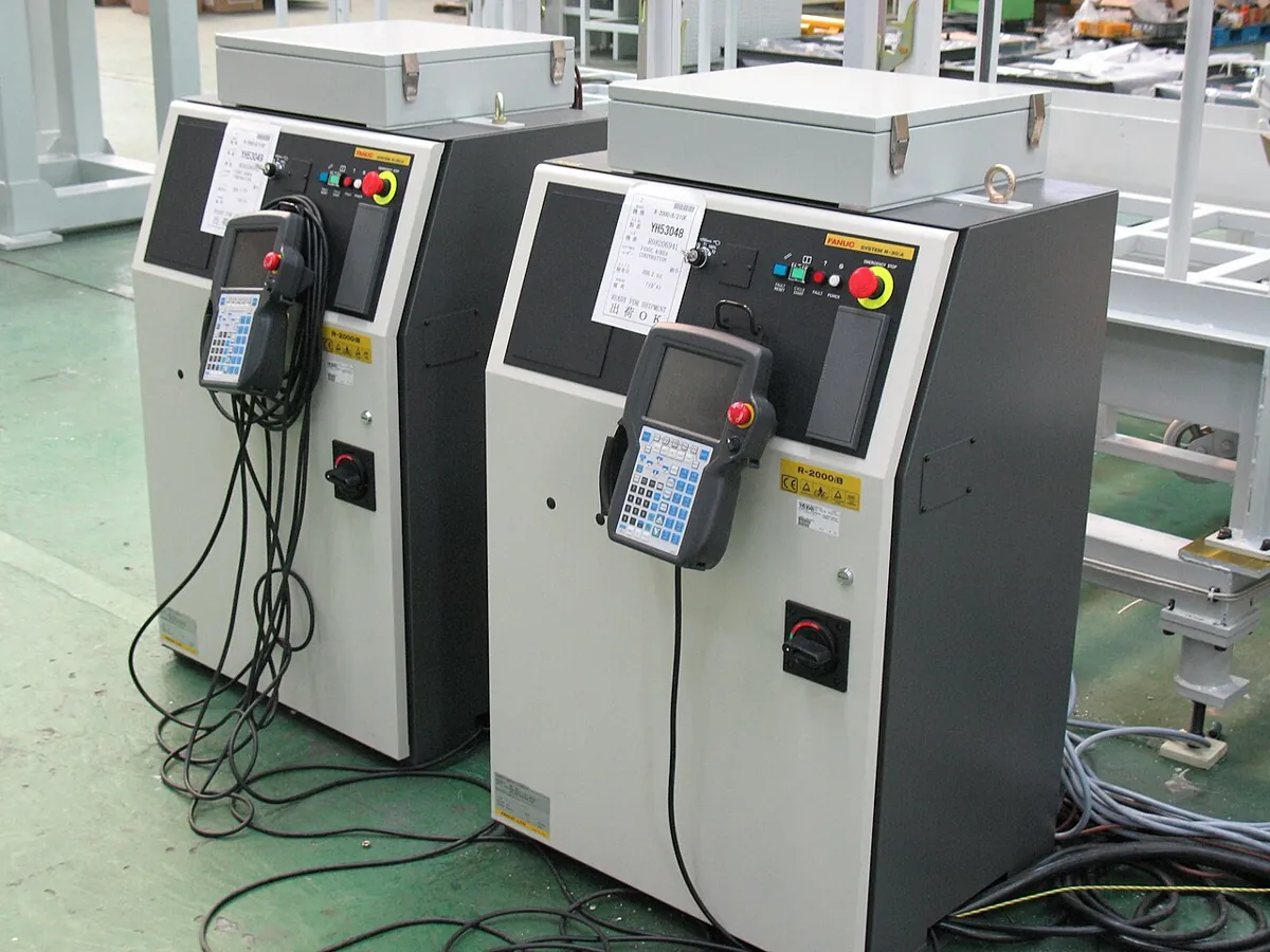
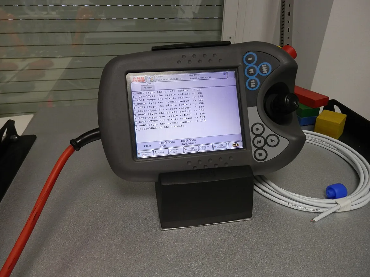
- Industrial robots: a separate control unit cabinet, plus a teach pendant for people to set targets.
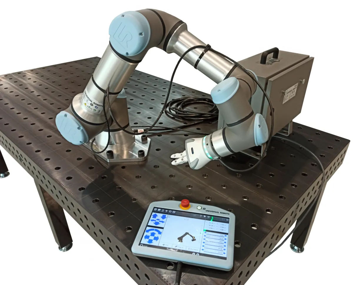
- Cobots: arm, controller box and touchscreen pendant work as separate layers.
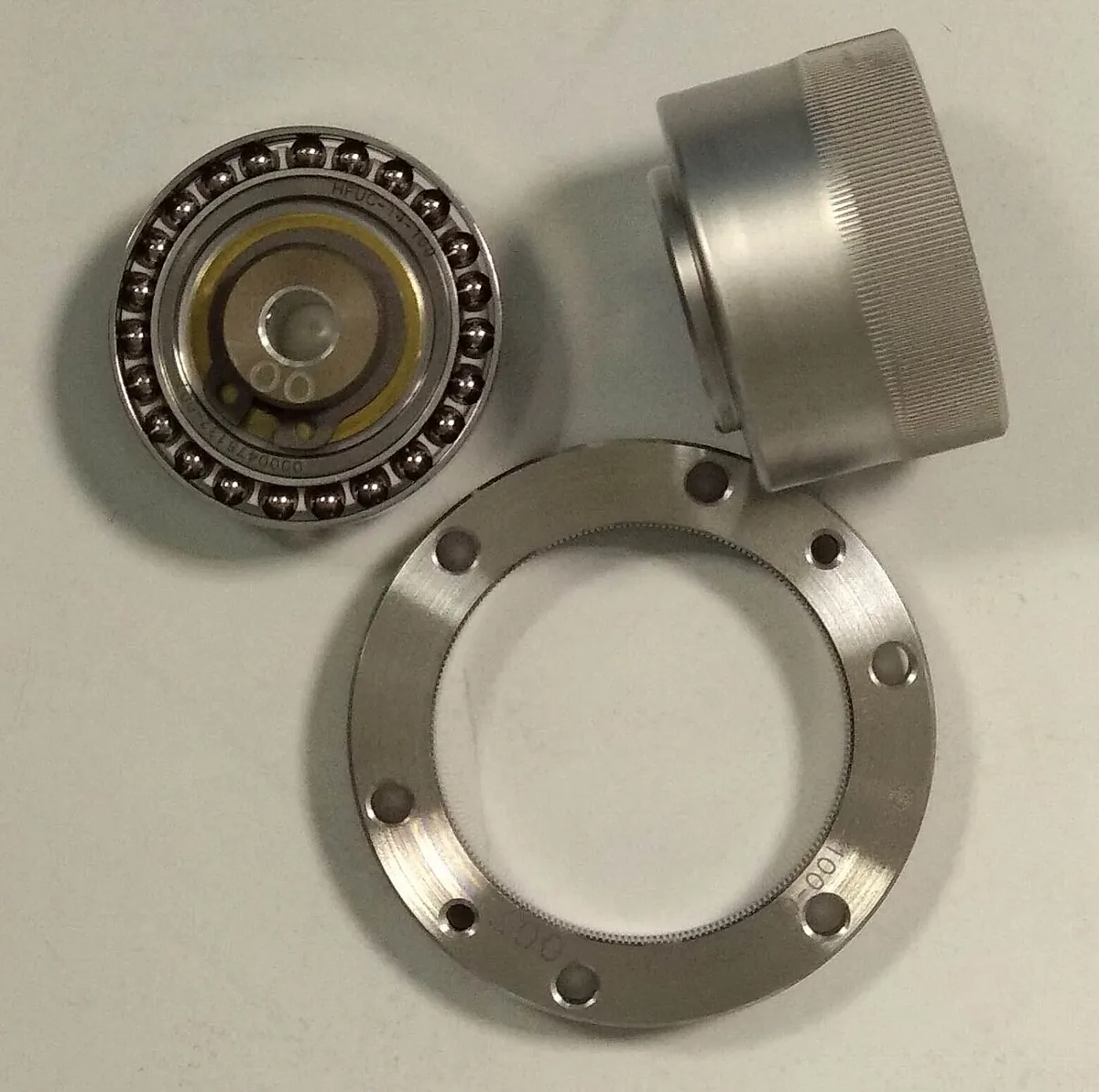
- Robot joints: gearboxes such as strain wave gears sit between motor and link.
- Modern Robotics: computed torque control = feedforward model + PID feedback.
Bench build
Bench build: a layered joint controller
Same hardware as Lessons 7 and 11 (DC gear motor with encoder, TB6612FNG, separate motor supply with fuse). joint_controller.ino is organised in the five layers: a cubic planner, feedforward + PID, limits, driver and sensor.
Wire as Lesson 11
PWMA 5, AIN1 7, AIN2 8, STBY 6; encoder 2/3; motor on its own supply with an inline fuse; grounds joined.
Set COUNTS_PER_REV
Turn the shaft one turn by hand and check the angle reads about 360°.
Move with FF_KICK = 0
Type 90, then 0. Read
plan,angleanderrin the printout. Note the biggest error during the move.Add feedforward
Set FF_KICK = 20 (helps the motor get past its friction). Repeat. Does the error during the move shrink?
Test each layer
Comment out the planner (jump straight to the goal) and compare. Then restore it.
// joint_controller.ino - one robot joint, built in clear LAYERS:
//   1. planner   : turns "go to 90" into a smooth angle-vs-time path (cubic, like the Python lab)
//   2. controller: feedforward (FF_KICK in the direction of motion) + PID on the path error
//   3. limits    : output limit, integral limit, slew limit
//   4. driver    : TB6612FNG with the motor on its OWN supply (never from an Arduino pin)
//   5. sensor    : quadrature encoder on pins 2/3
// Hardware as Lesson 7/11: PWMA 5, AIN1 7, AIN2 8, STBY 6; all grounds joined; fuse in motor supply.
const int PWMA = 5, AIN1 = 7, AIN2 = 8, STBY = 6, ENC_A = 2, ENC_B = 3;
const float COUNTS_PER_REV = 420.0;    // CHANGE THIS for your motor (output-shaft counts)
const float KP = 4.0, KI = 1.0, KD = 0.1;
const float FF_KICK = 20.0;            // PWM added while the plan is moving (friction feedforward)
const int PWM_LIMIT = 150, MAX_STEP_PWM = 10;
const float I_LIMIT = 40.0;
const unsigned long PERIOD_MS = 5;
const float DT = PERIOD_MS / 1000.0;

volatile long counts = 0;
void onEncA() { counts += (digitalRead(ENC_A) == digitalRead(ENC_B)) ? 1 : -1; }

// ---------- 1. planner ----------
float startDeg = 0, goalDeg = 0, moveTime = 1.0;
unsigned long moveStart = 0;
void planTo(float goal, float current) {
  startDeg = current; goalDeg = constrain(goal, -170, 170);
  moveTime = max(0.3, fabs(goalDeg - startDeg) / 90.0);    // about 90 deg per second
  moveStart = millis();
}
void plan(float &pos, float &vel) {
  float s = min((millis() - moveStart) / 1000.0 / moveTime, 1.0);
  pos = startDeg + (goalDeg - startDeg) * (3 * s * s - 2 * s * s * s);
  vel = (s < 1.0) ? (goalDeg - startDeg) * (6 * s - 6 * s * s) / moveTime : 0;
}

// ---------- 4. driver ----------
void drive(int u) {
  digitalWrite(AIN1, u > 0); digitalWrite(AIN2, u < 0); analogWrite(PWMA, abs(u));
}

float iTerm = 0, prevAngle = 0;
int lastU = 0;
unsigned long lastTick = 0;

void setup() {
  pinMode(PWMA, OUTPUT); pinMode(AIN1, OUTPUT); pinMode(AIN2, OUTPUT); pinMode(STBY, OUTPUT);
  pinMode(ENC_A, INPUT_PULLUP); pinMode(ENC_B, INPUT_PULLUP);
  attachInterrupt(digitalPinToInterrupt(ENC_A), onEncA, CHANGE);
  digitalWrite(STBY, HIGH);
  Serial.begin(115200);
  Serial.println(F("Type a goal angle in degrees, e.g. 90"));
}

void loop() {
  // ---------- 5. sensor ----------
  noInterrupts(); long c = counts; interrupts();
  float angle = c * 360.0 / COUNTS_PER_REV;

  if (Serial.available()) {
    float g = Serial.parseFloat();
    while (Serial.available()) Serial.read();
    planTo(g, angle);
  }
  if (millis() - lastTick < PERIOD_MS) return;
  lastTick = millis();

  // ---------- 2. controller ----------
  float pd, vd;
  plan(pd, vd);
  float speed = (angle - prevAngle) / DT;
  prevAngle = angle;
  float e = pd - angle;
  iTerm = constrain(iTerm + KI * e * DT, -I_LIMIT, I_LIMIT);            // 3. integral limit
  float ff = (vd > 0) ? FF_KICK : (vd < 0 ? -FF_KICK : 0);
  int u = (int)(ff + KP * e + iTerm + KD * (vd - speed));

  // ---------- 3. limits ----------
  u = constrain(u, -PWM_LIMIT, PWM_LIMIT);
  u = constrain(u, lastU - MAX_STEP_PWM, lastU + MAX_STEP_PWM);
  lastU = u;
  drive(u);

  static int n = 0;
  if (++n % 20 == 0) {
    Serial.print(F("plan=")); Serial.print(pd, 1);
    Serial.print(F(" angle=")); Serial.print(angle, 1);
    Serial.print(F(" err=")); Serial.print(e, 1);
    Serial.print(F(" u=")); Serial.println(u);
  }
}Debugging
Debugging a layered controller
| Symptom | Likely layer | Check |
|---|---|---|
| Joint jumps instead of moving smoothly | Planner | Is the path updated every tick? Is moveTime > 0? |
| Always lags the plan during moves | Controller (no feedforward) | Add speed/friction feedforward |
| Overshoots the end of the move | Controller or feedforward too big | Reduce FF_KICK or Kp; check Kd sign |
| Stops short, buzzes | Limits / friction | Integral limit too small; check PWM_LIMIT |
| Angle reads wrong or drifts | Sensor | COUNTS_PER_REV; encoder wiring; noise (Lesson 12) |
Think
Think about it
Think
Kabir’s arm follows slow moves well, but on fast moves the shoulder lags far behind the plan and then overshoots at the end. His PID gains are already high, and raising them makes it buzz. What layer would you change, and how?
Experiment
Try it in the lab: feedforward + feedback
About 35 minutes with the joint controller visual, the architecture script and (optionally) the motor bench.
Experiment
Feedforward + feedback
You will need
- Robot joint controller (in your browser)
- `joint_architecture.py`
- Optional: Arduino UNO, TB6612FNG, DC gear motor with encoder, battery pack, inline fuse
Steps
- Draw the five layers for your own arm’s shoulder joint, with the parts you would use.
- Run `joint_architecture.py`. Explain each row in one sentence.
- Try model errors of 0 %, 20 % and 50 %. Plot max error for ff only and ff + fb.
- In the joint controller visual, find a command where the joint clearly lags. Which layer would you improve?
- Optional bench: compare FF_KICK = 0 and 20 on `joint_controller.ino`.
Interactive · Robot joint controller · Capstone target 90°
θ now
0.0°
t
0.0s
Rise
1.75s
Overshoot
18.2%
|SSE|
1.94°
Capstone gate: |SSE| < 3°, overshoot < 25%, rise < 3.5s under load — PASS
Clear layers make a joint controller easy to test and fix. Feedforward does the predictable work; feedback cleans up the rest.
Knowledge check
Check your understanding
Knowledge check
1. The planner layer…
2. Feedforward uses…
3. Why does feedback-only control lag a planned move?
4. With a 20 % model error, feedforward only ended at…
5. Feedforward + feedback with a 20 % model error kept the max error to about…
6. Modern Robotics calls feedforward model + PID feedback…
7. Decentralised control means…
8. Decentralised control may not be good enough when…
9. When the full model is too hard to compute at servo rate, Modern Robotics suggests…
10. Why separate the controller into layers?
Mini assignment
Hands-on assignment
Mini assignment
Joint architecture sheet
Design and justify the control architecture for one joint of your arm.
Deliverables
- A layer diagram for one joint: planner, controller (ff + fb), limits, driver, sensor — with real part names.
- The model-error study from the code lab, as a small plot.
- A one-paragraph decision: decentralised or centralised control for your arm, and why.
- If you built it: printouts of `joint_controller.ino` with and without feedforward.
- A test plan: how you would test each layer on its own.
Do this, step by step
- Draw a layer diagram for one joint of your arm (planner, controller with feedforward and feedback, limits, driver, sensor) using real part names.
- Run
python3 joint_architecture.pyand copy the feedforward-only, feedback-only and both results. - Repeat the model-error study: add runs with
model_error= 0.4 and −0.2 next to the 20% case and sketch final error and peak as a small plot. - Decide decentralised or centralised control for your arm and write one paragraph on why.
- If you have the motor bench: flash
joint_controller.ino, run a move withFF_KICK= 0, then with 20.0, and save both printouts. Write a test plan that checks each layer on its own.
Stuck? Hints, one at a time
- Hint 1: Start from the motor and work up: driver → sensor → limits → controller → planner.
- Hint 2: Feedforward = what you can predict (acceleration, friction, gravity).
- Hint 3: For your 6-DOF arm, the shoulder carries the most gravity torque — that’s where gravity compensation helps most.
- Hint 4: To test the planner alone, print its path without the motor connected.
Challenges (pick by level)
- 🟢 Easy: Draw the five layers for a ceiling fan with a speed regulator.
- 🟢 Easy: Explain feedforward vs feedback using a cricket fielder catching a ball.
- 🟡 Medium: Add gravity feedforward (a constant) to
joint_controller.inofor a joint holding a small weight. - 🟡 Medium: Replace the cubic path with a trapezoidal speed profile and compare the max error.
- 🟠 Hard-ish: In
joint_architecture.py, make the load depend on the angle (LOAD × cos θ) like a real arm, and update the feedforward. - 🔴 Hard: Simulate two coupled joints and compare decentralised PID with a simple coupling compensation.
- ⚫ Research: Read Modern Robotics Sec. 11.4 on computed torque control and summarise Figure 11.19 in your own words.
Next step
Time to practise. In Lesson 14 — Practice: Response Lab Challenges you solve a set of tuning challenges using everything from this stage.
Look back: Lesson 12: Filtering Noisy Feedback. Next: Lesson 14: Practice: Response Lab Challenges. Related: Stage 6 — 6DOF Arm, Stage 8 — Kinematics & IK and Stage 10 — ROS 2 (ros2_control).
Sources
- Modern Robotics — K. M. Lynch & F. C. Park (preprint PDF) — Sec. 11.4: feedforward is used together with feedback; Eq. 11.35 computed torque (inverse dynamics) controller; Fig. 11.19 ff vs fb vs ff+fb; Sec. 11.4.2 decentralised vs centralised multi-joint control; PID plus gravity compensation when the full model is too expensive at servo rate.
- SparkFun — TB6612FNG Hookup Guide — driver wiring, supply ranges, STBY pin.
- Photos: Wikimedia Commons (credits under each image).
Self-attested for now — keep artifacts in your lab notebook.
Complete
Today's goal
0 of 1 done today
Mark this lesson complete when you have worked the experiment, knowledge check, and assignment (even roughly).