
Control Systems & PID · Lesson 05
Proportional Control (P)
Est. 60–75 min
Why
Why “push harder when you are further away” is the first controller
Proportional control (P) is the simplest real controller: the command is the error multiplied by a number, the proportional gain Kp. Big error → big command; small error → small command; zero error → zero command. It is easy to understand, easy to code (one line), and it already fixes most of the open-loop problems from Lessons 1–2. But it has two habits you must know: too much Kp causes overshoot and wobble, and under a steady load P leaves a small leftover error.
By the end of this lesson you will be able to: write the P control law; explain Kp as a “virtual spring” (*Modern Robotics*); predict what raising Kp does to rise time, overshoot and steady-state error (Michigan *Control Tutorials*); compute the P leftover error under gravity as load ÷ Kp; run a Kp sweep on a simulated joint; and tune a P controller on the LED + LDR bench loop.
Concept
How P control works — a virtual spring
Imagine pulling a door closed with a rubber band tied to the handle. When the door is wide open, the band is stretched far and pulls hard. As the door nears the frame, the band relaxes and pulls gently. The pull is proportional to the distance from closed. That is exactly what P control does with a motor.
u = Kp × e (e = setpoint − measured)
- u = command (torque, speed or PWM), Kp = proportional gain. *Modern Robotics* (Section 11.4.1) says the proportional gain acts as a virtual spring that tries to reduce the position error.
What Kp does — the famous table
| When you raise Kp… | Rise time | Overshoot | Settling time | Steady-state error |
|---|---|---|---|---|
| Effect | Decreases (faster) | Increases | Small change | Decreases, but not to zero |
The *Control Tutorials* explain why: a bigger Kp makes the controller “push” harder for the same error, so the system reacts more quickly — but it also overshoots more. It reduces, but does not eliminate, the steady-state error. Our simulated joint shows exactly this (see the code lab).
Why P leaves an error under gravity
To hold an arm out against gravity, the motor must keep producing a torque. With P control, torque = Kp × error — so the only way to get a non-zero holding torque is to keep a non-zero error. *Modern Robotics* says this directly for a joint under gravity: the joint comes to rest where Kp × error equals the gravity torque, so the final error is non-zero; you can make it smaller by raising Kp, but there are practical limits.
steady-state error (P only) = load torque ÷ Kp
- In the code lab: 0.05 N·m ÷ 0.01 N·m/° = 5°. Double Kp → half the error — and more overshoot.
| Kp (N·m/°) | Rise time | Overshoot | Final angle | Leftover error |
|---|---|---|---|---|
| 0.005 | 1.22 s | 7.7 % | 80.00° | 10.00° |
| 0.01 | 0.69 s | 20.8 % | 84.99° | 5.01° |
| 0.02 | 0.42 s | 35.1 % | 87.50° | 2.50° |
| 0.04 | 0.28 s | 48.6 % | 88.75° | 1.25° |
Why not just use a huge Kp?
- Overshoot and wobble: the joint arrives too fast and swings past the target (48.6 % at Kp = 0.04).
- Saturation: the motor has a torque/speed limit. Past it, a bigger Kp does nothing except cause bigger surprises (Lesson 11).
- Noise: Kp also multiplies sensor noise. A noisy reading × big Kp = a buzzing motor.
- Delay: with sensor or loop delay (Lesson 4), a high Kp can make the loop oscillate or go unstable.
Visual
Visualise it: sweep Kp
Keep **Ki = 0 and Kd = 0** and move only **Kp**. Small Kp: slow, with a leftover error. Large Kp: fast, but it overshoots and rings.
Interactive · PID visualizer

Setpoint 70° · final θ 69.1° · |SSE| 0.94° · constant load on
Teaching model: Kp↑ snappier (overshoot risk); Ki↑ reduces steady-state error under load; Kd↑ damps the edge.
Code lab
Code lab: a Kp sweep on a simulated joint
The script simulates a small joint with inertia, a little friction and a steady gravity load, controlled by torque = Kp × error. It measures rise time (10 %→90 %), overshoot, 2 % settling time, final angle and leftover error for four values of Kp, and compares the leftover error with load ÷ Kp. Run it with python3 p_control.py.
# p_control.py - proportional control of a robot joint, with a Kp sweep.
# Plant: a small joint with inertia, friction and a steady gravity load.
# (Angles are in degrees so the numbers stay readable; real controllers often work in radians.)
#   J * accel = torque - B * speed - LOAD          (torque limited to +/- TAU_MAX)
# Controller (P):  torque = Kp * error,  error = setpoint - angle   (angle in degrees)
J, B, LOAD, TAU_MAX = 0.002, 0.004, 0.05, 4.0      # N.m.s^2/deg, N.m.s/deg, N.m, N.m
SETPOINT, DT, T_END = 90.0, 0.001, 10.0

def step_response(kp):
    angle = speed = 0.0
    t, log = 0.0, []
    while t < T_END:
        error = SETPOINT - angle
        torque = max(-TAU_MAX, min(TAU_MAX, kp * error))
        accel = (torque - B * speed - LOAD) / J
        speed += accel * DT
        angle += speed * DT
        t += DT
        log.append((t, angle))
    return log

def metrics(log):
    final = sum(a for _, a in log[-1000:]) / 1000        # average of the last 1 s
    peak = max(a for _, a in log)
    t10 = next(t for t, a in log if a >= 0.1 * final)
    t90 = next(t for t, a in log if a >= 0.9 * final)
    band = 0.02 * abs(final)
    settle = 0.0
    for t, a in log:
        if abs(a - final) > band:
            settle = t
    over = max(0.0, (peak - final) / final * 100)
    return final, t90 - t10, over, settle

print(f"Setpoint {SETPOINT:.0f} deg, gravity load {LOAD} N.m, torque limit {TAU_MAX} N.m\n")
print(f"{'Kp (N.m/deg)':>12} {'rise 10-90%':>12} {'overshoot':>10} {'settle 2%':>10} {'final':>8} {'SSE':>7}")
for kp in (0.005, 0.01, 0.02, 0.04):
    final, rise, over, settle = metrics(step_response(kp))
    print(f"{kp:>12} {rise:>10.3f} s {over:>8.1f} % {settle:>8.2f} s {final:>6.2f}° {SETPOINT-final:>6.2f}°")
print("\nPredicted steady-state error for P only = LOAD / Kp:")
print("  " + ", ".join(f"Kp={kp}: {LOAD/kp:.2f}°" for kp in (0.005, 0.01, 0.02, 0.04)))
Output (run with python3 p_control.py)
Setpoint 90 deg, gravity load 0.05 N.m, torque limit 4.0 N.m

Kp (N.m/deg)  rise 10-90%  overshoot  settle 2%    final     SSE
       0.005      1.224 s      7.7 %     3.79 s  80.00°  10.00°
        0.01      0.689 s     20.8 %     3.73 s  84.99°   5.01°
        0.02      0.424 s     35.1 %     3.53 s  87.50°   2.50°
        0.04      0.275 s     48.6 %     3.78 s  88.75°   1.25°

Predicted steady-state error for P only = LOAD / Kp:
Kp=0.005: 10.00°, Kp=0.01: 5.00°, Kp=0.02: 2.50°, Kp=0.04: 1.25°Try it: set Ki and Kd to zero and sweep Kp. Watch rise time get shorter and overshoot get bigger.
Interactive · PID visualizer
Setpoint 70° · final θ 69.1° · |SSE| 0.94° · constant load on
Teaching model: Kp↑ snappier (overshoot risk); Ki↑ reduces steady-state error under load; Kd↑ damps the edge.
Real world
Proportional control in the real world
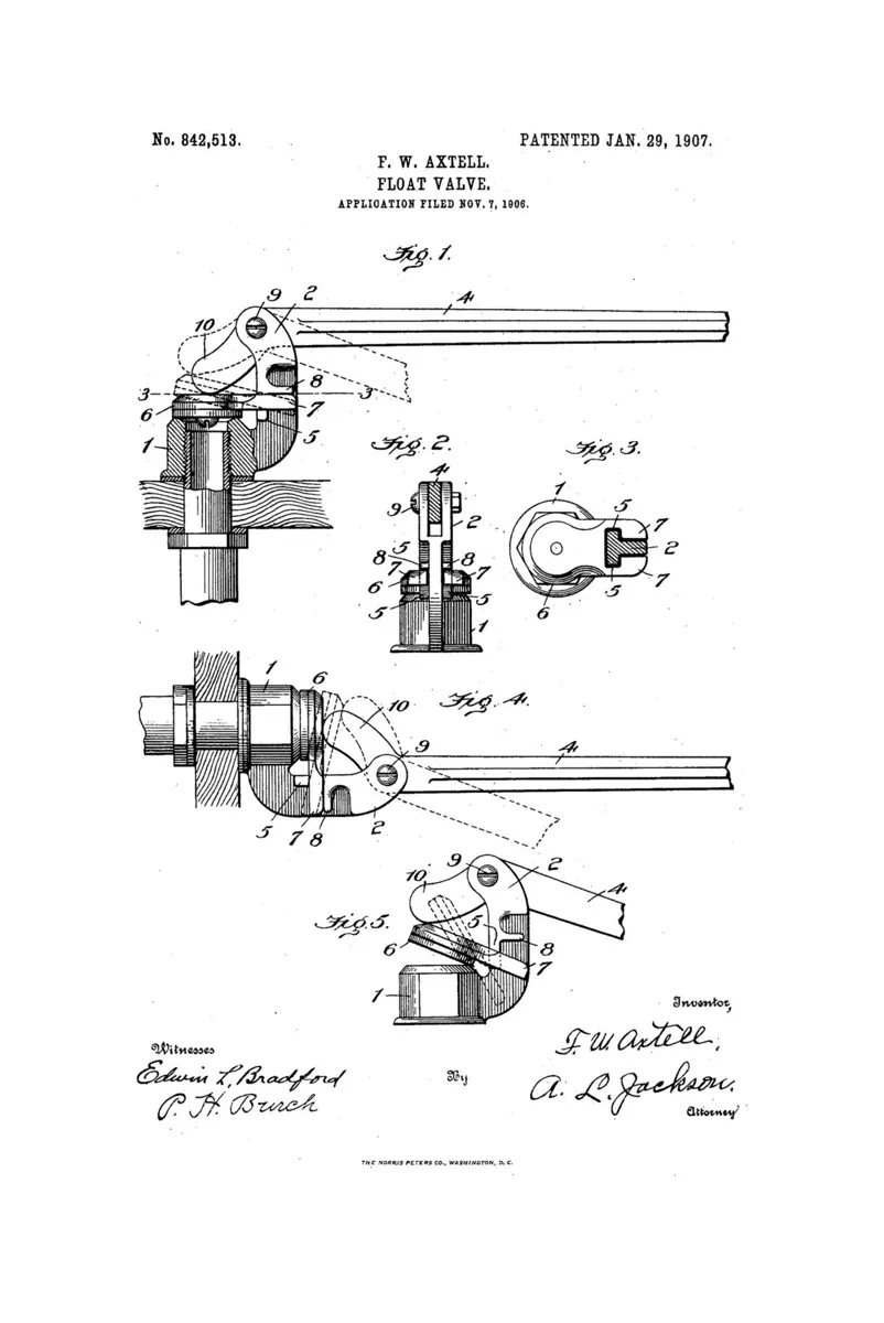
- Overhead water tanks: a float valve opens in proportion to how far the water is below full.
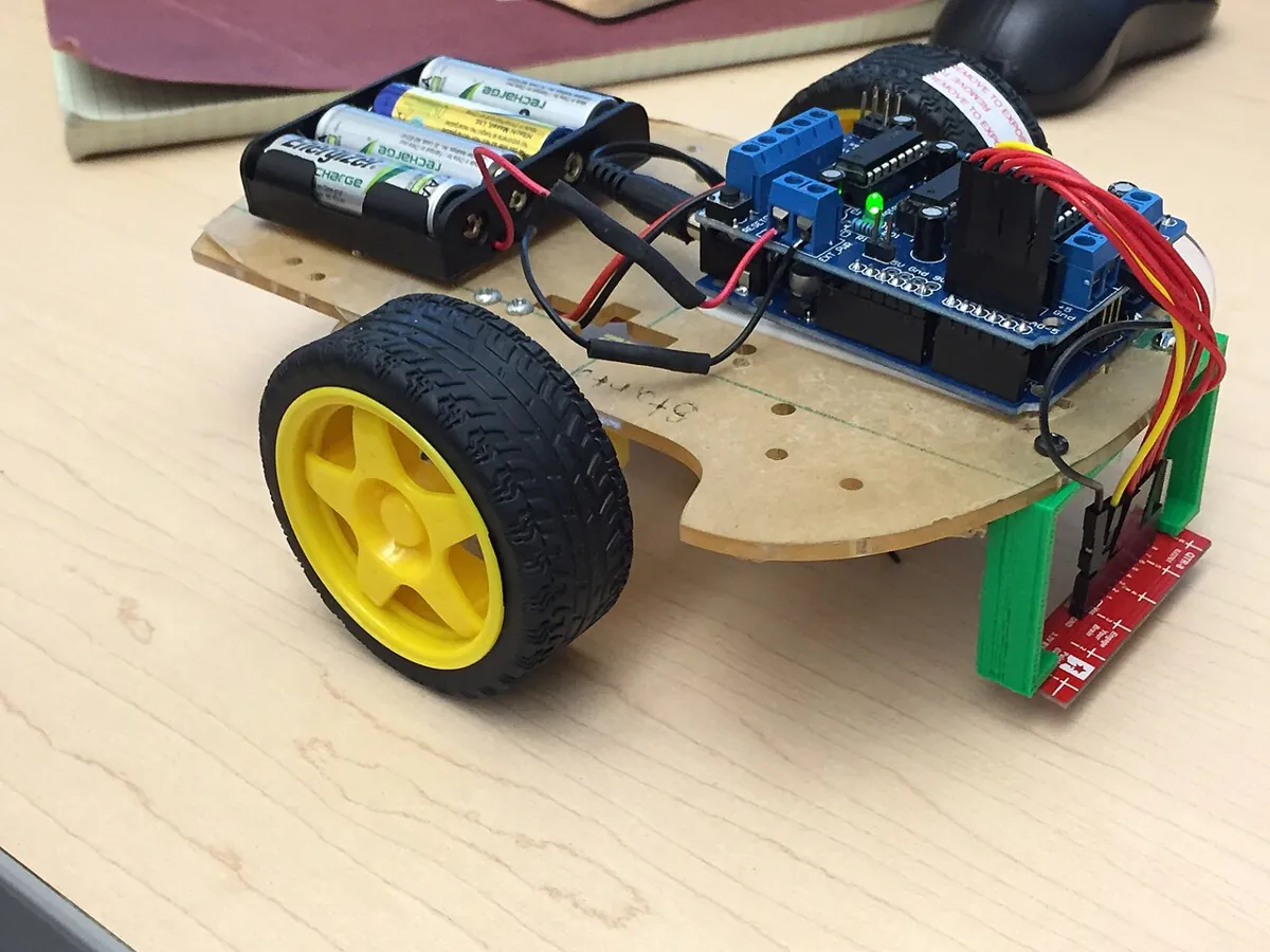
- Line followers: steering in proportion to how far the line is from the centre.
- Hobby servos: the electronics compare the commanded and measured positions and drive the motor until they match (SparkFun).
- Drones: the attitude loop pushes harder the further the drone is tilted from level (combined with D and I in practice).
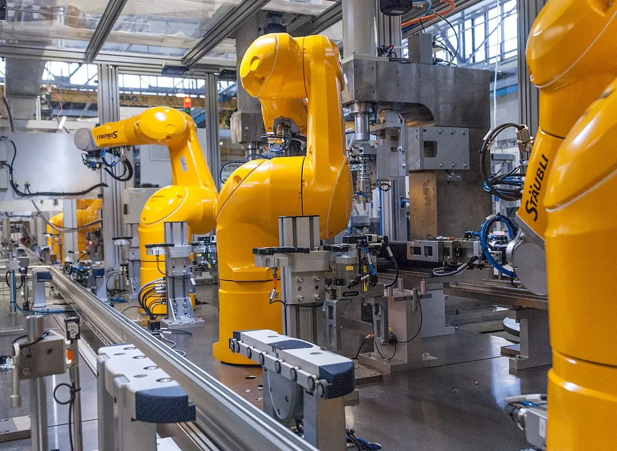
- Factory arms: every joint loop starts with a proportional term — the “virtual spring” of *Modern Robotics*.

Bench build
Bench build: P control on the light keeper
Same LED + LDR circuit as Lessons 2 and 4, now with a proper P controller: PWM = BIAS + KP × error. BIAS is a rough guess of the PWM needed (a tiny feedforward). Watch the Serial Plotter: P gets close, but a steady error remains unless BIAS happens to be exactly right.
Same wiring
Pin 9 → 220 Ω → LED → GND; 5 V → LDR → A0 → 10 kΩ → GND; paper tube around LED and LDR.
Upload with KP = 0.2
Open Serial Plotter at 115200. Note the steady error (setpoint − reading).
Sweep KP
Try 0.05, 0.2, 0.5 and 1.0. Record steady error and whether the reading wobbles.
Change BIAS
Set BIAS to 0 and then to 120 with KP = 0.2. How does the leftover error change? (This is the feedforward idea from Lesson 2.)
Disturb it
Shade the sensor halfway with a card. Note the new steady error — larger, because the controller now needs more PWM.
// p_light.ino - PROPORTIONAL control on the LED + LDR light keeper.
// pwm = BIAS + KP * error. Watch the steady error: P alone never quite reaches the setpoint
// unless BIAS happens to be exactly right. Try KP = 0.05, 0.2, 0.5 and note error and wobble.
// Wiring: pin 9 -> 220 ohm -> LED -> GND;  5V -> LDR -> A0 -> 10k -> GND.
const int LED_PIN = 9;
const int SENSOR_PIN = A0;
const int SETPOINT = 600;     // counts 0..1023 - choose one your LED can reach
const float KP = 0.2;         // PWM steps per count of error
const int BIAS = 60;          // a rough guess of the PWM needed (feedforward)
unsigned long lastTick = 0;

void setup() {
  pinMode(LED_PIN, OUTPUT);
  Serial.begin(115200);
  Serial.println(F("setpoint,reading,error,pwm"));
}

void loop() {
  if (millis() - lastTick < 20) return;          // 50 Hz
  lastTick = millis();
  int reading = analogRead(SENSOR_PIN);
  int error = SETPOINT - reading;
  int pwm = constrain(BIAS + (int)(KP * error), 0, 255);
  analogWrite(LED_PIN, pwm);
  Serial.print(SETPOINT); Serial.print(',');
  Serial.print(reading);  Serial.print(',');
  Serial.print(error);    Serial.print(',');
  Serial.println(pwm);
}Debugging
Debugging a P controller
| Symptom | Likely cause | Fix |
|---|---|---|
| Slow, lazy response | Kp too small | Double Kp until it feels quick |
| Overshoots and wobbles | Kp too big for the plant | Halve Kp; later add D (Lesson 7) |
| Small error that never goes away | P only, steady load | Normal — add feedforward or I (Lesson 6) |
| Output slams to the limit and stays | Sign wrong (positive feedback) | Flip the sign of the error or the actuator |
| Motor/LED buzzes or flickers at rest | Kp × sensor noise | Average the sensor; add a small dead band; lower Kp |
| Bigger Kp makes no difference | Actuator saturated | Check the command against its limit |
Think
Think about it
Think
Meera’s arm holds 90° nicely when it is empty, but when she hangs a 100 g weight on the gripper it sags to 86°. Arjun says, “Just multiply Kp by 10.” Explain what will probably happen, and suggest a better approach.
Experiment
Try it in the lab: the P sweep
About 35 minutes with the PID visualiser, the script and the light keeper.
Experiment
The P sweep
You will need
- PID visualiser (in your browser)
- Notebook, graph paper
- Optional: `p_control.py`; Arduino UNO, LED, 220 Ω, LDR, 10 kΩ
Steps
- In the visualiser, set Ki = Kd = 0. Try four Kp values; sketch each response.
- Run `p_control.py`. Plot Kp (x-axis) against overshoot and against leftover error.
- Check that leftover error × Kp ≈ 0.05 N·m for every row.
- Set `LOAD = 0` and rerun. Explain the new leftover error.
- Optional bench: run `p_light.ino` with four KP values; record steady error and wobble.
Interactive · PID visualizer
Setpoint 70° · final θ 69.1° · |SSE| 0.94° · constant load on
Teaching model: Kp↑ snappier (overshoot risk); Ki↑ reduces steady-state error under load; Kd↑ damps the edge.
Raising Kp trades a slow, inaccurate response for a fast, overshooting one. P alone can’t remove the error under a steady load — but it’s the backbone of every PID loop.
Knowledge check
Check your understanding
Knowledge check
1. Increasing Kp alone typically…
2. The P control law is…
3. Modern Robotics compares the proportional gain to…
4. Gravity load 0.05 N·m, Kp = 0.02 N·m/°. The P leftover error is…
5. Why does P control need a leftover error to hold an arm against gravity?
6. Which effect of raising Kp did the code lab show as “small change”?
7. A very large Kp is a bad idea mainly because…
8. In `p_light.ino`, BIAS is…
9. A float valve in a water tank is an example of…
10. When tuning Kp, a good step size is…
Mini assignment
Hands-on assignment
Mini assignment
P journal
Tune a proportional controller with evidence: a Kp sweep, a leftover-error check and a short recommendation.
Deliverables
- A table and a hand-drawn plot of Kp vs rise time, overshoot and leftover error from `p_control.py` (at least four Kp values, including one of your own).
- A check that leftover error × Kp equals the load for every row, with one sentence explaining why.
- Your choice of Kp for this joint with a one-paragraph justification (what you traded for what).
- If you built it: steady error and wobble for four KP values on `p_light.ino`, and what changing BIAS did.
- One paragraph: where does a P controller hide in your home or school?
Do this, step by step
- Run
python3 p_control.pyand copy the Kp sweep table (rise time, overshoot, leftover error). - Add one Kp value of your own, run again, and plot Kp vs overshoot and Kp vs leftover error by hand.
- For every row check that leftover error × Kp ≈ load, and write one sentence on why P alone always leaves an error under load.
- In the PID visualiser set Ki = Kd = 0 and sweep Kp; note where overshoot first appears.
- If you have the light keeper: flash
p_light.inowithKP= 0.2, then 0.1, 0.4 and 0.8; record steady error and wobble, then changeBIASfrom 60 and note what changes. Finish with your chosen Kp and a short justification.
Stuck? Hints, one at a time
- Hint 1: Change only
kpvalues in the sweep tuple; don’t touch the plant. - Hint 2: For your choice, decide first what matters most: no overshoot, or small error.
- Hint 3: If the bench reading never reaches the setpoint even with high KP, the setpoint may be too bright for your LED — lower it.
- Hint 4: Overshoot % = (peak − final) ÷ final × 100.
Challenges (pick by level)
- 🟢 Easy: Predict the leftover error for Kp = 0.08 before you run it.
- 🟢 Easy: What are the units of Kp if the error is in degrees and the command is PWM?
- 🟡 Medium: Add gravity feedforward:
torque = kp*error + LOAD. What happens to the leftover error? - 🟡 Medium: Add a 5 ms sensor delay to
p_control.py. Find the Kp at which the joint starts to oscillate without settling. - 🟠 Hard-ish: Write a P line follower in Python: a point robot, a straight line and a P steering law. Plot its path for three gains.
- 🔴 Hard: Make the gravity load depend on angle (
LOAD * cos(angle)). Where is the P leftover error largest, and why? - ⚫ Research: Read *Modern Robotics* Section 11.4.1 (PD control and second-order error dynamics) and explain Eq. 11.27 in your own words.
Next step
In Lesson 6 — Integral Control (I) you give the controller a memory: it adds up the error over time and builds exactly the torque gravity needs, so the leftover error disappears.
Look back: Lesson 4: Control Loop Anatomy. Next: Lesson 6: Integral Control (I). Related: Stage 5 L08: Feedback & Closed-Loop Control and Stage 4 L09: PWM & Motor/Servo Control.
Sources
- Control Tutorials (University of Michigan) — Introduction: PID Controller Design — increasing Kp pushes harder for the same error, reacts more quickly but tends to overshoot more, and reduces but does not eliminate steady-state error; effect table (rise time, overshoot, settling time, S-S error); “these guidelines hold in many cases, but not all”.
- Modern Robotics — K. M. Lynch & F. C. Park (preprint PDF) — Sec. 11.3: Kp acts somewhat like a virtual spring; Sec. 11.4.1: PID law τ = Kp θe + Ki∫θe + Kd θ̇e; under gravity, PD/P control rests where Kp θe equals the gravity torque, so the final error is non-zero; it can be reduced by raising Kp but there are practical limits.
- SparkFun Learn: Hobby Servo Tutorial — the servo drives its motor until the potentiometer matches the commanded pulse width.
- Photos and diagrams: Wikimedia Commons (credits under each image).
Self-attested for now — keep artifacts in your lab notebook.
Complete
Today's goal
0 of 1 done today
Mark this lesson complete when you have worked the experiment, knowledge check, and assignment (even roughly).