
Control Systems & PID · Lesson 15
Capstone: Tune a Robot Joint
Est. 90–120 min
Why
Why a capstone
This is the last lesson of Stage 7. There is no new theory. You will take one robot joint — an arm link lifted against gravity — and tune it until it meets written goals, not just until it ‘looks fine’. Then you will prove the tune is robust by testing it with a heavier payload, a heavier arm and different sensor noise, and you will write a short tuning report like a real engineer.
By the end of this lesson you will be able to: plan and run a full tuning session on one joint; meet four goals at once (overshoot, settling time, steady-state error and torque noise); use gravity feedforward or an I term to fight a load that changes with angle; check that your tune survives a 25 % change in the joint; and write a clear tuning report with your gains, metrics and safety limits.
Concept
The capstone brief
The joint you will tune
The joint is an arm link that starts hanging straight down (0°) and must lift to level (90°). Gravity pulls with a torque of G × sin(angle): zero at the bottom and biggest when the arm is level. So the load grows exactly when you need to stop — that is what makes this joint harder than the ones in Lesson 14.
| Part | Value | From lesson |
|---|---|---|
| Inertia J / damping B | 0.003 / 0.004 | 5–8 (the plant) |
| Gravity G (torque at level) | 0.12 | 6 (a load needs I or feedforward) |
| Torque limit | ±1.5 | 11 (saturation) |
| Sensor noise | ±0.05° (random) | 12 (filtering) |
| Anti-windup | Conditional integration | 11 |
| Derivative | On measurement, with an EMA filter (alpha) | 7 and 12 |
| Optional gravity feedforward | G × sin(angle) from the model | 13 |
The capstone goals
| Goal | Limit | Why it matters |
|---|---|---|
| Overshoot | ≤ 10 % | The arm must not swing past level and hit something |
| Settling time (2 % band) | ≤ 2.0 s | The arm must be ready for the next task quickly |
| |SSE| (average of the last 0.5 s) | ≤ 0.5° | The flag must really be level |
| Torque noise (last 1 s) | ≤ 0.15 | A shaking command heats the motor and wears the gears |
A tune only passes the capstone if it meets all four goals in all four tests: the nominal joint, a payload 25 % heavier, an arm with 25 % more inertia, and another noise seed (different random noise). This is how you show your tune has margin, not luck.
| Test | Overshoot | Settle | SSE | Torque noise | Result |
|---|---|---|---|---|---|
| nominal joint | 25.9 % | 4.00 s | 4.66° | 0.446 | try again |
| payload +25 % | 26.2 % | 4.00 s | 6.09° | 0.447 | try again |
| inertia +25 % | 33.1 % | 4.00 s | 6.33° | 0.465 | try again |
| another noise seed | 25.9 % | 4.00 s | 4.66° | 0.437 | try again |
Read this report like a doctor. The arm overshoots by about 26 % and never settles (4.00 s means it was still outside the band at the end). It stops about 4.7° short because gravity pulls it down and there is no I term or feedforward. And the motor command shakes by about ±0.45 because the derivative of a noisy sensor is not filtered. Every one of these has a fix you learnt in this stage.
Tuning plan
Your tuning plan: one change at a time
1. Measure first
Run the starting gains and copy the report into your tuning log. Write which goals fail.
2. Fix the shaking
Lower alpha (try 0.1, then 0.03) to filter the derivative. Torque noise should drop. Re-check overshoot — a heavy filter adds delay (Lesson 12).
3. Get speed with Kp
Raise Kp step by step. The arm rises faster but overshoots more (Lesson 5).
4. Add damping with Kd
Raise Kd to bring the overshoot back down (Lesson 7). Kp and Kd usually go up together.
5. Kill the gravity error
Either add a small Ki (Lesson 6) or switch on GRAVITY_FF (Lesson 13). Try both and compare.
6. Test the margin
Only when the nominal test passes, look at the payload, inertia and noise tests. Fix the weakest one.
Visual
Visualise it: the capstone joint
The capstone joint: set a target of 90°, add load, and watch rise time, overshoot and |SSE|. Tune until the banner reads **PASS**.
Interactive · Robot joint controller · Capstone target 90°
θ now
0.0°
t
0.0s
Rise
1.75s
Overshoot
18.2%
|SSE|
1.94°
Capstone gate: |SSE| < 3°, overshoot < 25%, rise < 3.5s under load — PASS
Code lab
Code lab: capstone_tune.py
capstone_tune.py simulates the joint 1000 times a second for 4 seconds. Edit the five lines under YOUR TUNE — KP, KI, KD, ALPHA and GRAVITY_FF — and run python3 capstone_tune.py. It prints one line per test and tells you when the whole capstone has passed.
# capstone_tune.py - Stage 7 capstone: tune ONE robot joint to 90 deg and write a tuning report.
# The joint is an arm link lifted from hanging straight down (0 deg) to horizontal (90 deg),
# so gravity pulls harder the higher it goes: gravity torque = G * sin(angle).
# Everything from Lessons 5-14 is here: PID, torque limit, conditional-integration anti-windup,
# an EMA filter on the derivative, noisy sensor, and optional gravity feedforward (Lesson 13).
import math
import random

DT, T_END, TARGET = 0.001, 4.0, 90.0
J, B, G, TAU_MAX, NOISE = 0.003, 0.004, 0.12, 1.5, 0.05  # inertia, damping, gravity, torque limit, noise (deg)
GOAL = dict(overshoot=10.0, settle=2.0, sse=0.5, torque_noise=0.15)

# ---- YOUR TUNE: change these, run again, and keep a log ----
KP, KI, KD = 0.02, 0.0, 0.002     # PID gains (torque per degree, per degree-second, per degree/s)
ALPHA = 1.0                       # derivative filter: 1.0 = no filter, smaller = more filtering
GRAVITY_FF = False                # True = add the model's gravity torque G*sin(angle) (Lesson 13)


def run(j=J, g=G, kp=KP, ki=KI, kd=KD, alpha=ALPHA, ff=GRAVITY_FF, seed=7):
    r = random.Random(seed)
    angle = speed = integral = d_filt = 0.0
    prev_meas = 0.0
    ys, taus = [], []
    for _ in range(int(T_END / DT)):
        meas = angle + r.gauss(0.0, NOISE)
        e = TARGET - meas
        d_raw = -(meas - prev_meas) / DT            # derivative on measurement: no kick at the step
        prev_meas = meas
        d_filt += alpha * (d_raw - d_filt)
        tau_ff = G * math.sin(math.radians(meas)) if ff else 0.0   # the MODEL uses the design G
        u = tau_ff + kp * e + ki * integral + kd * d_filt
        tau = max(-TAU_MAX, min(TAU_MAX, u))
        if tau == u or (u > TAU_MAX and e < 0) or (u < -TAU_MAX and e > 0):
            integral += e * DT                       # conditional integration (Lesson 11)
        acc = (tau - B * speed - g * math.sin(math.radians(angle))) / j
        speed += acc * DT
        angle += speed * DT
        ys.append(angle)
        taus.append(tau)
    return ys, taus


def metrics(ys, taus):
    final = sum(ys[-500:]) / 500                     # average of the last 0.5 s
    peak = max(ys)
    overshoot = max(0.0, (peak - final) / final * 100) if final > 1 else 0.0
    band = 0.02 * TARGET
    settle = T_END
    for i in range(len(ys) - 1, -1, -1):
        if abs(ys[i] - TARGET) > band:
            settle = (i + 1) * DT
            break
    else:
        settle = 0.0
    last = taus[-1000:]
    noise = (max(last) - min(last)) / 2
    return dict(overshoot=overshoot, settle=settle, sse=TARGET - final,
                torque_noise=noise, peak_torque=max(abs(t) for t in taus))


def verdict(m):
    checks = [m["overshoot"] <= GOAL["overshoot"], m["settle"] <= GOAL["settle"],
              abs(m["sse"]) <= GOAL["sse"], m["torque_noise"] <= GOAL["torque_noise"]]
    return "PASS" if all(checks) else "try again"


def report(title, **kw):
    m = metrics(*run(**kw))
    print(f"{title:<24} {m['overshoot']:>6.1f}% {m['settle']:>6.2f}s {m['sse']:>7.2f}° "
          f"{m['torque_noise']:>7.3f} {m['peak_torque']:>6.2f}  {verdict(m)}")
    return verdict(m)


print(f"Capstone: 0 -> {TARGET:.0f} deg, gravity G = {G}, torque limit {TAU_MAX}, noise ±{NOISE}°")
print(f"Gains: Kp {KP}, Ki {KI}, Kd {KD}, alpha {ALPHA}, gravity FF {GRAVITY_FF}")
print(f"Goals: overshoot ≤ {GOAL['overshoot']:.0f} %, settle ≤ {GOAL['settle']} s, "
      f"|SSE| ≤ {GOAL['sse']}°, torque noise ≤ {GOAL['torque_noise']}\n")
print(f"{'test':<24} {'over':>7} {'settle':>7} {'SSE':>8} {'t-noise':>7} {'peak':>6}  result")
results = [
    report("nominal joint"),
    report("payload +25 %", g=G * 1.25),
    report("inertia +25 %", j=J * 1.25),
    report("another noise seed", seed=11),
]
print("\nCAPSTONE PASSED - write your report!" if all(r == "PASS" for r in results)
      else "\nNot yet: every test must PASS. Change one thing at a time and log it.")
Output with the starting gains (run with python3 capstone_tune.py)
Capstone: 0 -> 90 deg, gravity G = 0.12, torque limit 1.5, noise ±0.05°
Gains: Kp 0.02, Ki 0.0, Kd 0.002, alpha 1.0, gravity FF False
Goals: overshoot ≤ 10 %, settle ≤ 2.0 s, |SSE| ≤ 0.5°, torque noise ≤ 0.15

test                        over  settle      SSE t-noise   peak  result
nominal joint              25.9%   4.00s    4.66°   0.446   1.50  try again
payload +25 %              26.2%   4.00s    6.09°   0.447   1.50  try again
inertia +25 %              33.1%   4.00s    6.33°   0.465   1.50  try again
another noise seed         25.9%   4.00s    4.66°   0.437   1.50  try again

Not yet: every test must PASS. Change one thing at a time and log it.
Warm up here first: tune Kp, Ki and Kd under load until the capstone banner says PASS (this widget uses a simpler gate: |SSE| < 3°, overshoot < 25 %, rise < 3.5 s). Then take the harder goals to the code.
Interactive · Robot joint controller · Capstone target 90°
θ now
0.0°
t
0.0s
Rise
1.75s
Overshoot
18.2%
|SSE|
1.94°
Capstone gate: |SSE| < 3°, overshoot < 25%, rise < 3.5s under load — PASS
Real world
Tuned joints in the real world
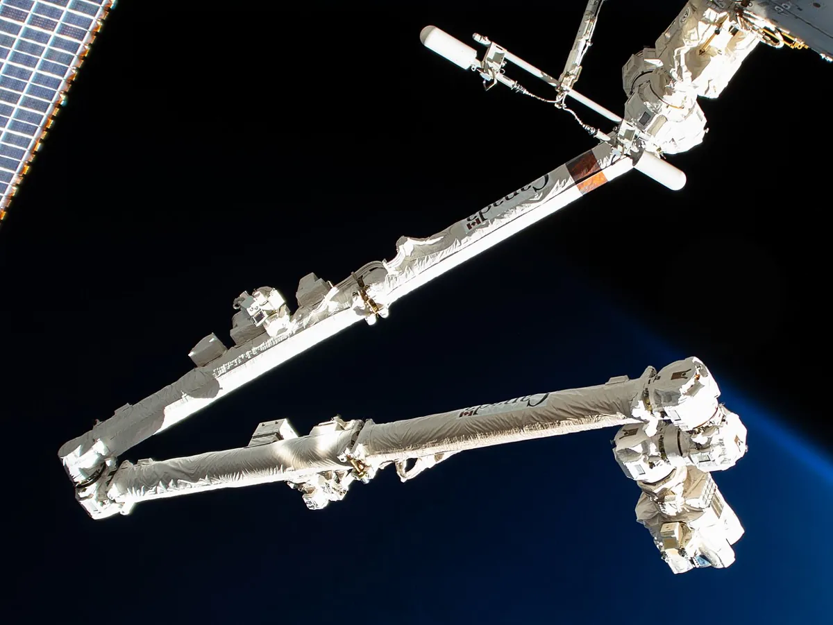
- Space robotics: big arms like Canadarm2 on the International Space Station move heavy payloads slowly and precisely; every joint is tested against written limits before a real task.
- Factory robots: a joint tune is accepted only after tests with the lightest and heaviest tools and payloads the robot will carry.
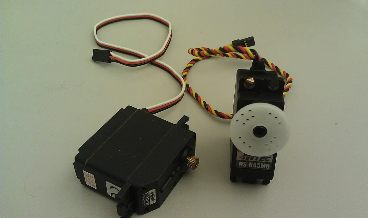
- Hobby servos and 3D printers: the same PID ideas, tuned once at the factory or with an auto-tune routine, run inside cheap everyday devices.
- Your next stages: trajectory planning and kinematics assume the joints follow their commands. A well-tuned joint is what makes those stages work.
Bench build
Bench build: the capstone on a real motor joint
If you built the motor + encoder joint from Lessons 7, 11 and 13, run the same capstone on real hardware. capstone_joint.ino runs a 4-second step test to 90°, prints the angle every 0.1 s (paste it into a spreadsheet to plot it), and finishes with overshoot, settling time, SSE and PASS or TRY AGAIN. You can change the gains from the Serial Monitor without re-uploading.
| From | To | Note |
|---|---|---|
| Arduino pin 5 | TB6612FNG PWMA | Motor speed (PWM) |
| Arduino pins 7 / 8 | AIN1 / AIN2 | Motor direction |
| Arduino pin 6 | STBY | Driver enable — LOW = motor off |
| Arduino 5 V / GND | TB6612FNG VCC / GND | Logic power only |
| Motor battery + (through a fuse) | TB6612FNG VM | The motor’s OWN supply, never the Arduino 5 V pin |
| Motor battery − | Common GND | All grounds joined |
| AO1 / AO2 | Motor terminals | — |
| Encoder A / B | Arduino pins 2 / 3 | Encoder powered from 5 V and GND |
Set up safely
Clamp the motor to the bench. Fit a light arm (a ruler or a strip of card) to the shaft. Keep fingers and cables clear of its swing.
Check COUNTS_PER_REV
Turn the shaft one full turn by hand and check the angle reads about 360°. Fix
COUNTS_PER_REVif not.Run the first test
Open Serial Monitor at 115200, hold the arm hanging down, type
gand keep a finger near theskey.Tune from the keyboard
Type e.g.
p3ord0.1to change a gain, thengagain. Follow the same plan as the code lab.Test the margin
Tape a coin to the end of the arm (more payload) and test again. Does your tune still pass?
// capstone_joint.ino - Stage 7 capstone on real hardware: tune ONE motor joint to 90 deg.
// Same bench as Lessons 7, 11 and 13: DC gear motor + quadrature encoder, TB6612FNG driver.
// The MOTOR has its OWN supply (with a fuse) on VM. The Arduino only sends logic signals.
// Never power a motor or servo from an Arduino pin. All grounds joined.
// Serial 115200: type  g  = run the 90 deg step test,  s  = STOP (motor off),
//                     p0.05 / i0.01 / d0.002  = set Kp / Ki / Kd, then g again.
const int PWMA = 5, AIN1 = 7, AIN2 = 8, STBY = 6, ENC_A = 2, ENC_B = 3;
const float COUNTS_PER_REV = 420.0;          // CHANGE THIS for your motor (output-shaft counts)
const int PWM_LIMIT = 150;                   // safety: never full power on the bench
const float SOFT_LIMIT_DEG = 135.0;          // safety: cut the motor if the joint goes past this
const float TARGET = 90.0, TEST_S = 4.0;
const float OS_GOAL = 10.0, SETTLE_GOAL = 2.0, SSE_GOAL = 1.0;   // capstone gates (bench)
const unsigned long PERIOD_MS = 5;
const float DT = PERIOD_MS / 1000.0;

float KP = 2.0, KI = 0.0, KD = 0.05;         // starting tune - improve it!
const float ALPHA = 0.2;                     // EMA filter on the derivative (Lesson 12)

volatile long counts = 0;
void onEncA() { counts += (digitalRead(ENC_A) == digitalRead(ENC_B)) ? 1 : -1; }

void drive(int u) {
  digitalWrite(AIN1, u > 0); digitalWrite(AIN2, u < 0); analogWrite(PWMA, abs(u));
}
void stopMotor() { drive(0); digitalWrite(STBY, LOW); }

float readAngle() {
  noInterrupts(); long c = counts; interrupts();
  return c * 360.0 / COUNTS_PER_REV;
}

bool stopRequested() {
  if (Serial.available() && Serial.peek() == 's') { Serial.read(); return true; }
  return false;
}

void stepTest() {
  noInterrupts(); counts = 0; interrupts();       // start position = 0 deg
  digitalWrite(STBY, HIGH);
  float integral = 0, dFilt = 0, prev = 0, peak = 0, sum = 0;
  int nLast = 0;
  float settle = 0;
  unsigned long t0 = millis(), last = t0;
  const int steps = (int)(TEST_S / DT);
  for (int k = 0; k < steps; ) {
    if (stopRequested()) { stopMotor(); Serial.println(F("# STOP")); return; }
    if (millis() - last < PERIOD_MS) continue;
    last += PERIOD_MS; k++;
    float a = readAngle();
    if (fabs(a) > SOFT_LIMIT_DEG) { stopMotor(); Serial.println(F("# SOFT LIMIT - motor off")); return; }
    float e = TARGET - a;
    dFilt += ALPHA * (-(a - prev) / DT - dFilt);  // derivative on measurement, filtered
    prev = a;
    float u = KP * e + KI * integral + KD * dFilt;
    float uc = constrain(u, -PWM_LIMIT, PWM_LIMIT);
    if (uc == u) integral += e * DT;              // conditional integration (Lesson 11)
    drive((int)uc);
    float t = k * DT;
    if (a > peak) peak = a;
    if (fabs(e) > 0.02 * TARGET) settle = t;      // last time outside the 2 % band
    if (t > TEST_S - 0.5) { sum += a; nLast++; }  // final value = average of last 0.5 s
    if (k % 20 == 0) { Serial.print(t, 2); Serial.print(','); Serial.println(a, 1); }
  }
  stopMotor();
  float fin = sum / nLast;
  float os = fin > 1 ? max(0.0, (peak - fin) / fin * 100.0) : 0.0;
  float sse = TARGET - fin;
  bool pass = os <= OS_GOAL && settle <= SETTLE_GOAL && fabs(sse) <= SSE_GOAL;
  Serial.print(F("# Kp ")); Serial.print(KP, 3); Serial.print(F(" Ki ")); Serial.print(KI, 3);
  Serial.print(F(" Kd ")); Serial.print(KD, 3);
  Serial.print(F(" | overshoot ")); Serial.print(os, 1); Serial.print(F(" % settle "));
  Serial.print(settle, 2); Serial.print(F(" s SSE ")); Serial.print(sse, 2);
  Serial.println(pass ? F(" deg -> PASS") : F(" deg -> TRY AGAIN"));
}

void setup() {
  pinMode(PWMA, OUTPUT); pinMode(AIN1, OUTPUT); pinMode(AIN2, OUTPUT); pinMode(STBY, OUTPUT);
  pinMode(ENC_A, INPUT_PULLUP); pinMode(ENC_B, INPUT_PULLUP);
  attachInterrupt(digitalPinToInterrupt(ENC_A), onEncA, CHANGE);
  stopMotor();                                    // motor OFF until you ask for a test
  Serial.begin(115200);
  Serial.println(F("# Capstone joint. Hold the arm at 0 deg, then type g. Type s to STOP."));
}

void loop() {
  if (!Serial.available()) return;
  char c = Serial.read();
  if (c == 'g') stepTest();
  else if (c == 's') { stopMotor(); Serial.println(F("# STOP")); }
  else if (c == 'p') KP = Serial.parseFloat();
  else if (c == 'i') KI = Serial.parseFloat();
  else if (c == 'd') KD = Serial.parseFloat();
  else return;
  if (c == 'p' || c == 'i' || c == 'd') {
    Serial.print(F("# gains now Kp ")); Serial.print(KP, 3); Serial.print(F(" Ki "));
    Serial.print(KI, 3); Serial.print(F(" Kd ")); Serial.println(KD, 3);
  }
}
Debugging
Debugging your capstone
| Report says | Likely cause | Try |
|---|---|---|
| Settle 4.00 s and big SSE | Gravity not handled | Add a small Ki, or switch on GRAVITY_FF |
| Torque noise ≈ the torque limit | Unfiltered derivative of a noisy sensor | Lower alpha to 0.1 or 0.03 |
| Overshoot rises when you raise Kp | Not enough damping | Raise Kd together with Kp |
| Nominal passes, inertia +25 % fails on overshoot | Too little damping margin | Raise Kd a little more |
| FF + Ki together: SSE goes negative | The integral is still unwinding after the rise | Use FF with a very small Ki, or no Ki |
| Bench: arm runs the wrong way and hits the soft limit | Motor or encoder wires swapped | Swap AO1/AO2 (or encoder A/B) with the power off |
| Bench: TRY AGAIN with ‘settle’ near 4 s | Static friction stops the arm just short | A small Ki helps; check the arm is not rubbing |
Think
Think about it
Think
Ananya passes the nominal test with Kp 0.08, Ki 0.02, Kd 0.015 and alpha 1.0 — except torque noise is 1.5. She says, “The motor is just loud, it still gets to 90°.” What would you tell her, and what one change fixes it?
Experiment
Try it in the lab: pass the capstone
About 60–90 minutes with capstone_tune.py, the joint widget and (optionally) the motor bench.
Experiment
Pass the capstone
You will need
- Robot joint controller and PID tuning lab (in your browser)
- `capstone_tune.py` and Python 3
- Your tuning log (notebook or spreadsheet)
- Optional bench: Arduino UNO, TB6612FNG driver, DC gear motor with encoder, separate motor battery with fuse, a light arm, jumper wires
Steps
- In the joint widget, tune to PASS under load. Write down the gains — this is your warm-up.
- Run `capstone_tune.py` with the starting gains and copy the report into your log.
- Follow the tuning plan: alpha → Kp → Kd → Ki or GRAVITY_FF. One change per run, one log line per run.
- When all four tests pass, try a second solution: if you used Ki, now try GRAVITY_FF instead (or the other way round). Compare the payload +25 % SSE of the two.
- Margin test: raise G in the code to 0.18 (50 % heavier). Which of your two solutions still passes?
- Optional bench: get `capstone_joint.ino` to PASS, then tape a coin to the arm and test again.
Interactive · Robot joint controller · Capstone target 90°
θ now
0.0°
t
0.0s
Rise
1.75s
Overshoot
18.2%
|SSE|
1.94°
Capstone gate: |SSE| < 3°, overshoot < 25%, rise < 3.5s under load — PASS
Filtering the derivative fixes the shaking but adds a little delay; Kp and Kd go up together; and a load that changes with angle is handled either by an I term (which learns it slowly) or by feedforward (which knows it from the model). Feedforward is only as good as the model — that is why the payload test matters.
Knowledge check
Check your understanding
Knowledge check
1. In the capstone joint, gravity torque is G × sin(angle). Where is it biggest?
2. The starting report shows torque noise ≈ 0.45 and the arm never settles. The first fix in the tuning plan is…
3. Which two tools can remove the steady-state error caused by gravity?
4. Why does capstone_tune.py take the derivative of the measurement instead of the error?
5. A tune passes the nominal test but fails ‘inertia +25 %’ on overshoot. The best next try is…
6. On the bench, the motor should be powered from…
7. What does conditional integration do while the motor is saturated?
8. When is a capstone tune finished?
Mini assignment
Capstone report
Mini assignment
Capstone tuning report
Pass the capstone and write a one- or two-page tuning report that another student could follow to get the same result.
Deliverables
- Your final `KP`, `KI`, `KD`, `ALPHA` and `GRAVITY_FF`, and the full CAPSTONE PASSED output of `capstone_tune.py`.
- Your tuning log — every try, its four metrics and its result.
- A short paragraph per step of your plan: what you changed, what happened, and which lesson explains it.
- A comparison of two solutions (Ki vs gravity feedforward) under the payload test, and which you would choose for a real arm and why.
- Your safety limits: torque or PWM limit, soft angle limit, STOP method, separate motor supply and fuse.
- If you built the bench: the PASS line from `capstone_joint.ino`, a plot of angle vs time and a photo of your setup.
Do this, step by step
- Run
python3 capstone_tune.pywith the starting gains and copy the four metrics againstGOAL(overshoot 10%, settle 2 s, error 0.5°, torque noise 0.15). - Follow the six-step plan above — measure, fix shaking (
ALPHA), Kp for speed, Kd for damping, kill gravity error, test the margin — changing one thing per run and logging every try. - Solve the gravity error twice: once with Ki, once with
GRAVITY_FF = True; compare both under the payload test and choose one for a real arm. - Write your safety limits: PWM limit, soft angle limit, STOP method, separate motor supply and fuse.
- If you have the motor bench: flash
capstone_joint.ino, tune from the keyboard until the PASS line appears, and save a plot of angle vs time and a photo. Then write the one- or two-page tuning report.
Stuck? Hints, one at a time
- Hint 1: Start with alpha. With alpha = 0.03 the torque noise falls below 0.1 for most gains.
- Hint 2: The starting Kd (0.002) is far too small for this arm. Try Kd values near 0.01–0.02 with Kp near 0.08.
- Hint 3: For the gravity error, Ki = 0.02 is enough. Or set Ki = 0 and GRAVITY_FF = True.
- Hint 4: One set that passes is Kp 0.08, Ki 0.02, Kd 0.015, alpha 0.03. Now find a faster one — the fastest we found settles in about 1.0 s.
Challenges (pick by level)
- 🟢 Easy: Pass the joint widget under load and record your gains.
- 🟢 Easy: Get torque noise below 0.15 in all four tests (ignore the other goals for now).
- 🟡 Medium: Pass the full capstone in
capstone_tune.py. - 🟡 Medium: Pass it two ways — with Ki and with gravity feedforward.
- 🟠 Hard-ish: Add a fifth test, ‘payload +50 %’ (G × 1.5), and pass all five.
- 🔴 Hard: Change TARGET to 45° and then 135°. Does one tune pass all three targets? Explain using G × sin(angle).
- ⚫ Research: Write a small search that tries many gain sets and prints the one with the shortest worst-case settling time that still passes. Compare it with your hand tune and explain the difference.
Stage 7 checklist
- ☐ I can explain why robots need feedback control, and open vs closed loop (Lessons 1–2)
- ☐ I can name the setpoint, sensor, error and the parts of a control loop (Lessons 3–4)
- ☐ I know what P, I and D each do (Lessons 5–8)
- ☐ I can measure rise time, overshoot, settling time and SSE (Lesson 9)
- ☐ I can follow a tuning plan and handle saturation, windup and noise (Lessons 10–12)
- ☐ I can explain feedforward + feedback in a joint controller (Lesson 13)
- ☐ I passed the response lab challenges and this capstone (Lessons 14–15)
Next step
You have finished Stage 7 — Control Systems & PID. Your joints now follow their commands. Next, open the Master Roadmap and move on to the next stage, where you will plan *what* those well-tuned joints should do.
Look back: Lesson 14: Practice: Response Lab Challenges and Lesson 11: Saturation, Windup & Safety Limits. You have finished Stage 7! Next: Stage 8 — Kinematics & IK. Related: Stage 9 — Trajectory Planning, Stage 6 — 6DOF Arm and Stage 12 — Simulation & Digital Twin.
Sources
- Control Tutorials for MATLAB & Simulink — Introduction: PID Controller Design — effects of P, I and D; general tips for designing a PID controller; saturation, windup and noise as practical challenges.
- Wikipedia — Integral windup — why windup happens with a saturated actuator, and fixes including conditional integration and bounding the integral.
- Wikipedia — Proportional–integral–derivative controller — “Derivative of the process variable”: taking the derivative of the measurement instead of the error, so a setpoint step does not cause a derivative kick. (Brett Beauregard’s Arduino PID Library uses the same idea: github.com/br3ttb/Arduino-PID-Library.)
- Photos: Wikimedia Commons, public domain (credits under each image).
Self-attested for now — keep artifacts in your lab notebook.
Complete
Today's goal
0 of 1 done today
Mark this lesson complete when you have worked the experiment, knowledge check, and assignment (even roughly).