
Control Systems & PID · Lesson 02
Open Loop vs Closed Loop
Est. 55–70 min
Why
Why the same command gives different results
In Lesson 1 you saw that a plan alone breaks when the world changes. Now we put the two kinds of control side by side, with numbers. An open-loop controller decides the command from the goal alone and never looks at the result. A closed-loop controller measures the result and uses the error to decide the command. Both are useful — the skill is knowing which one to use, and how to combine them.
By the end of this lesson you will be able to: draw both loops as block diagrams; run the textbook cruise-control car with open-loop, P-only and plan-plus-feedback controllers; explain why P-only control settles a little below the target; explain why *Modern Robotics* recommends feedforward plus feedback; and build an LED-and-light-sensor loop on the bench that holds its brightness when you cover it with your hand.
Concept
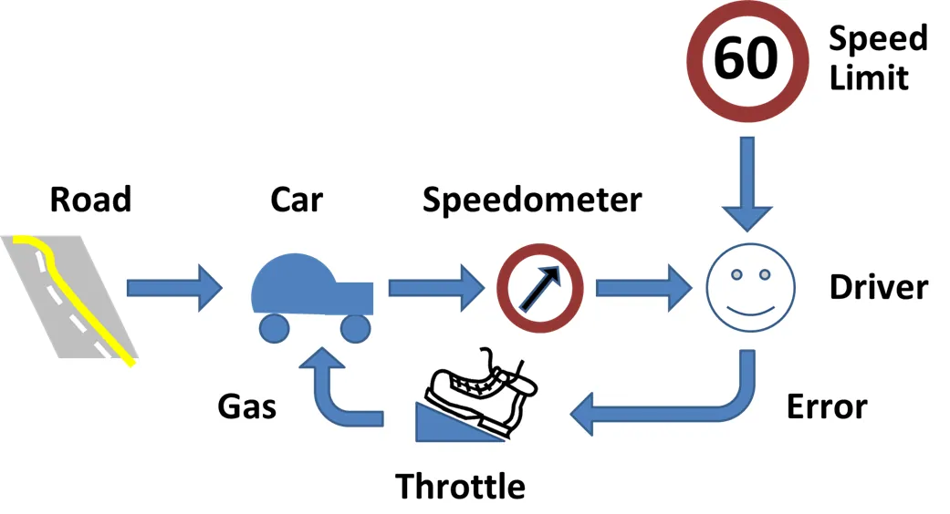
Open loop, closed loop, and the best of both
Think of making tea on a gas stove. The open-loop way: “boil for exactly 4 minutes”. It works on your stove with your vessel — and boils over on your aunt’s bigger burner. The closed-loop way: watch the tea, lower the flame when it rises, switch off when it looks right. The open-loop way needs no attention but trusts the world to match the plan; the closed-loop way pays attention and handles surprises.
The two block diagrams
| Open loop (feedforward) | Closed loop (feedback) | |
|---|---|---|
| How it decides | From the goal (and a model) only | From the error = setpoint − measurement |
| Sensor needed? | No | Yes |
| Handles disturbances? | No — errors pile up | Yes — it sees and corrects them |
| Starts moving when… | Immediately, from the plan | Only once an error exists |
| Can it go unstable? | Not by itself (but can be badly wrong) | Yes, if the gain is too high or the sensor lags |
| Examples | Timer toaster, stepper without encoder, fixed throttle | Cruise control, thermostat, hobby servo, balancing robot |
*Modern Robotics* (Section 11.3) is direct about both. Feedforward (open-loop) control needs no sensor data, but in practice position errors accumulate over time. Feedback control fixes that — but it has its own drawback: an error is required before the joint begins to move. So the book’s preferred controller combines them: a feedforward term from the planned motion plus a feedback correction. It even says that because there are always modelling errors, feedforward control is always used together with feedback.
command = feedforward (from the plan) + Kp × error (from the sensor)
- The plan does most of the work and starts the motion at once; the feedback term cleans up whatever the plan didn’t expect.
The textbook cruise-control car
The University of Michigan *Control Tutorials* model a car as a mass pushed by a force u from the tyres and held back by a resistance proportional to speed: m·dv/dt = u − b·v, with m = 1000 kg and b = 50 N·s/m. On a flat road, holding 10 m/s (36 km/h) needs u = b·v = 50 × 10 = 500 N. That is our open-loop plan. Then at t = 20 s the road starts climbing and a 300 N grade force pulls the car back.
| Controller | Speed just before the hill | Speed on the hill (60 s) | Why |
|---|---|---|---|
| Open loop, 500 N fixed | 6.31 m/s (still rising) | 4.31 m/s, heading for 4.0 | Never notices the hill; also slow, because m/b = 20 s |
| P only, Kp = 500 | 9.09 m/s | 8.55 m/s | Needs some error to make force |
| P only, Kp = 2000 | 9.76 m/s | 9.61 m/s | Bigger gain → smaller leftover error |
| 500 N plan + P (Kp = 500) | 10.00 m/s | 9.45 m/s | Plan handles the flat road; feedback fights the hill |
Look at the P-only rows on the flat road. The car settles at Kp·10 / (Kp + 50), not at 10 m/s: with Kp = 500 that is 9.09 m/s. P control needs a leftover error to keep producing force. A bigger Kp shrinks it; adding the plan (feedforward) removes it on the flat road; the integral term in Lesson 6 will remove it on the hill too.
When is open loop the right choice?
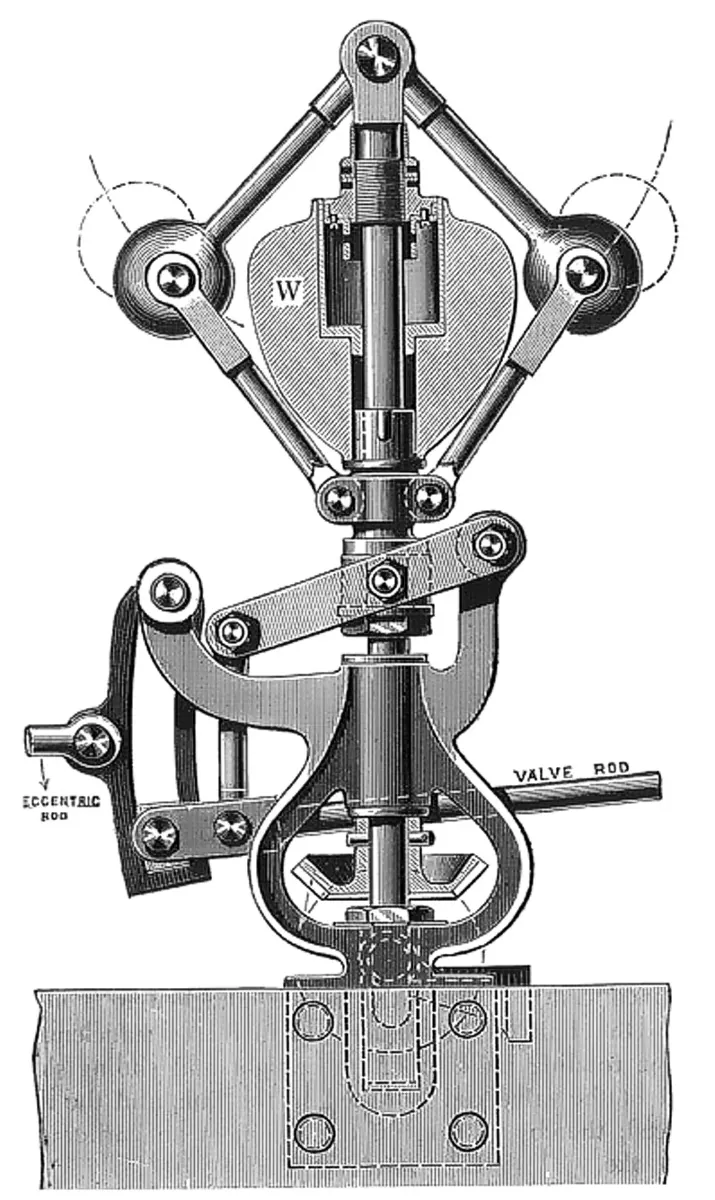
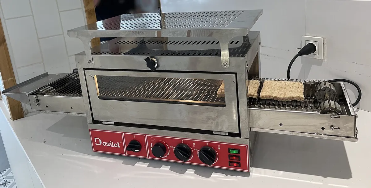
- When the world is predictable and errors don’t matter much — a timer toaster, a washing-machine rinse cycle.
- When you can’t measure the output easily — and you can accept small errors.
- As a helper inside a closed loop — the feedforward term in the formula above.
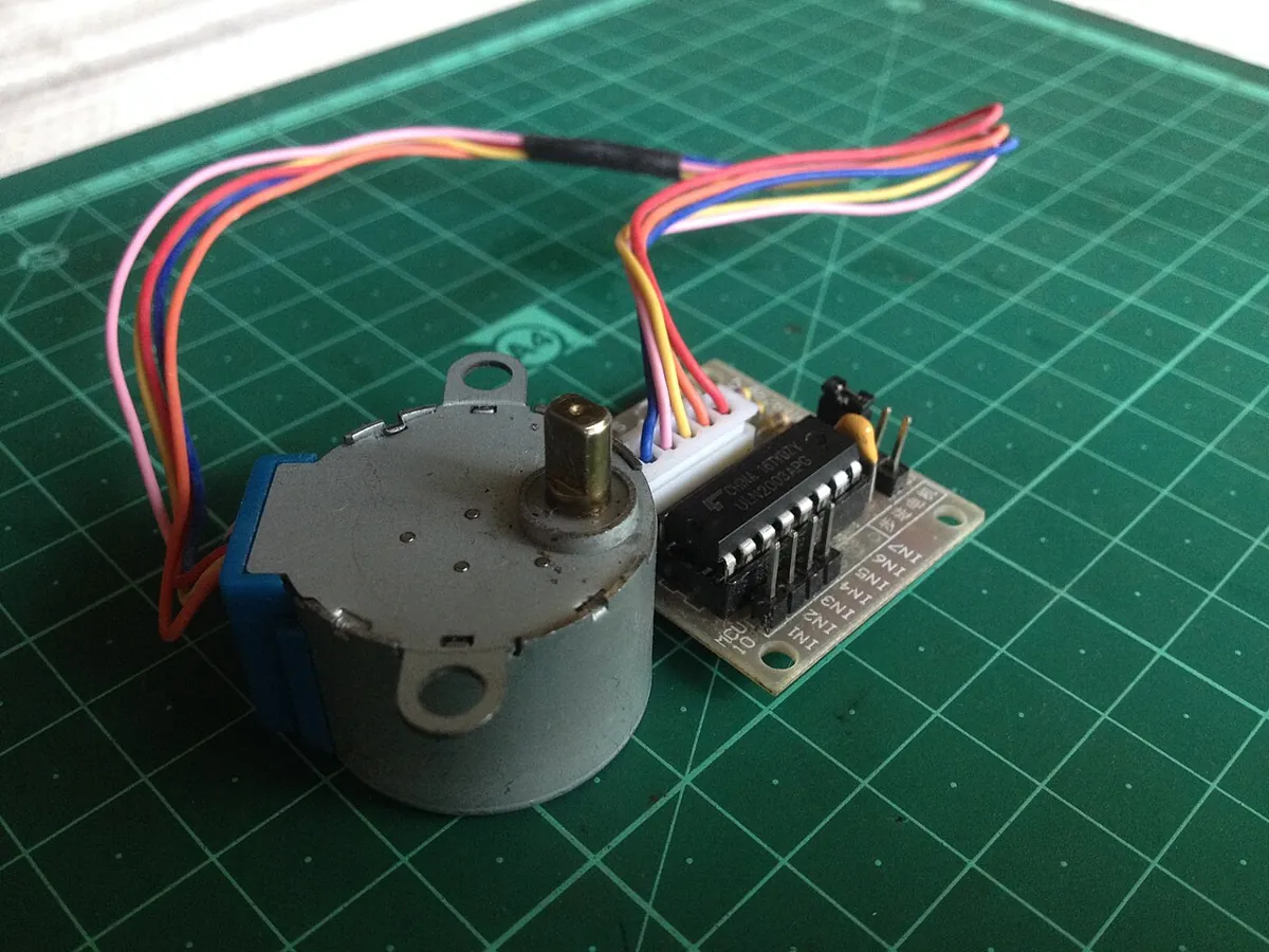
- When stepping motors are run well within their torque — a 3D printer’s stepper counts steps open loop, and re-homes to limit switches to clear any error.
Visual
Visualise it: disturb both loops
Run the same setpoint in **open loop** and **closed loop**, then add the same disturbance to both. Watch which one notices and corrects.
Interactive · Control loop explorer

Mode
Closed
θ final
61.6°
Error
-1.6°
Closed-loop uses error = setpoint − feedback. Open-loop ignores feedback — load disturbances leave steady-state error.
Code lab
Code lab: four controllers on the same car and the same hill
This script uses the University of Michigan cruise-control model (m = 1000 kg, b = 50 N·s/m). It compares a fixed 500 N throttle, two P-only controllers and a plan-plus-feedback controller. A 300 N hill starts at t = 20 s. Run it with python3 open_vs_closed.py.
# open_vs_closed.py - open loop vs closed loop on the textbook cruise-control car.
# Model and numbers from the University of Michigan "Control Tutorials for MATLAB and Simulink":
#   m * dv/dt = u - b * v      with m = 1000 kg, b = 50 N.s/m
# We want 10 m/s (36 km/h). At t = 20 s the road starts climbing: a grade force of 300 N pulls back.

M, B = 1000.0, 50.0      # kg, N.s/m (CTMS cruise-control parameters)
V_SET = 10.0             # m/s target speed
DT, T_END = 0.1, 60.0
HILL_AT, HILL_FORCE = 20.0, 300.0
U_MAX = 2000.0           # N, the engine cannot push harder than this

def simulate(controller):
    v, t, log = 0.0, 0.0, {}
    while t <= T_END + 1e-9:
        u = max(0.0, min(U_MAX, controller(v)))
        hill = HILL_FORCE if t >= HILL_AT else 0.0
        if any(abs(t - s) < 1e-6 for s in (5, 10, 19.9, 30, 60)):
            log[round(t, 1)] = (v, u)
        v += (u - B * v - hill) / M * DT
        t += DT
    return log

open_loop = lambda v: B * V_SET             # "flat road needs 500 N" -> push 500 N forever
def p_control(kp):
    return lambda v: kp * (V_SET - v)       # push harder when we are slower than 10 m/s
def p_plus_feedforward(kp):
    return lambda v: B * V_SET + kp * (V_SET - v)   # plan (500 N) + feedback correction

runs = [("open loop (500 N fixed)", open_loop),
        ("P only, Kp = 500", p_control(500)),
        ("P only, Kp = 2000", p_control(2000)),
        ("500 N plan + Kp = 500", p_plus_feedforward(500))]
print("Target 10.0 m/s. Hill (300 N) starts at t = 20 s.\n")
print(f"{'controller':<26}" + "".join(f"{'v@'+str(s)+'s':>9}" for s in (5, 10, 19.9, 30, 60)))
for name, c in runs:
    log = simulate(c)
    print(f"{name:<26}" + "".join(f"{log[s][0]:>9.2f}" for s in (5, 10, 19.9, 30, 60)))
print("\nSteady speed with P only on a flat road = Kp*10/(Kp+50):",
      ", ".join(f"Kp={k}: {k*10/(k+B):.2f} m/s" for k in (500, 2000)))
print("Open loop on the hill settles at (500-300)/50 =", (500 - 300) / 50, "m/s - it never notices.")
Output (run with python3 open_vs_closed.py)
Target 10.0 m/s. Hill (300 N) starts at t = 20 s.

controller                     v@5s    v@10s  v@19.9s    v@30s    v@60s
open loop (500 N fixed)        2.22     3.94     6.31     5.41     4.31
P only, Kp = 500               7.95     9.02     9.09     8.55     8.55
P only, Kp = 2000              8.87     9.76     9.76     9.61     9.61
500 N plan + Kp = 500          8.44     9.91    10.00     9.46     9.45

Steady speed with P only on a flat road = Kp*10/(Kp+50): Kp=500: 9.09 m/s, Kp=2000: 9.76 m/s
Open loop on the hill settles at (500-300)/50 = 4.0 m/s - it never notices.
Try it: hold the water at the line. Add a leak (a disturbance) and compare a fixed inflow with a feedback-controlled inflow.
Interactive · Water tank: float switch vs timer
Overflow wasted
0 L
Minutes dry
0 min
Pump running
74 min
Pump switchings
4
Model: 1000 L tank, starts at 300 L, simulated minute by minute for 3 hours. Float switch = closed loop (it senses the level). Timer = open loop (it never looks at the tank).
Real world
Open and closed loops around you
- Open loop: timer toaster, microwave timer, ceiling-fan regulator, a stepper motor counting steps.
- Closed loop: cruise control, refrigerator and AC thermostats, a water-tank float valve, hobby servos, drone flight controllers.
- Both together: robot arms use the planned motion as feedforward and add feedback on each joint — the controller *Modern Robotics* calls its preferred one.
- 3D printers: steppers run open loop, but re-home to limit switches so errors cannot pile up across prints.
Bench build
Bench build: the light keeper (open vs closed loop)
An LED shines on a light-dependent resistor (LDR). The Arduino reads the LDR and drives the LED with PWM. In open loop the LED gets a fixed value. In closed loop the Arduino nudges the brightness until the reading matches a setpoint — so when you shade the sensor, the LED brightens to compensate. It is a complete feedback loop for about ₹50 of parts.
LED (actuator)
Pin 9 → 220 Ω resistor → LED long leg (anode); LED short leg → GND.
LDR divider (sensor)
5 V → LDR → A0, and A0 → 10 kΩ → GND. More light → lower LDR resistance → higher reading.
Face them
Bend the LED so it points at the LDR from about 1 cm away. A small paper tube around both cuts room light.
Open loop first
Set
CLOSED_LOOP = false, upload, open Serial Plotter at 115200. Shade the pair with your hand: the reading drops and stays down.Close the loop
Set
CLOSED_LOOP = true. PickSETPOINTa little below the highest reading you saw. Upload and shade again: the PWM rises and the reading climbs back to the setpoint.
// light_keeper.ino - open loop vs closed loop with an LED and a light sensor (LDR).
// The LED (with a 220 ohm resistor) shines on an LDR. The LDR + 10 k resistor divider feeds A0.
// OPEN LOOP : the LED gets a fixed PWM value - room light changes, nothing reacts.
// CLOSED LOOP: every 20 ms we compare the reading with the setpoint and nudge the PWM.
// Cover the sensor with your hand or shine a torch on it and watch each mode.
// A single LED with its resistor draws about 10-15 mA - fine for a pin. Never drive motors from a pin.
const int LED_PIN = 9;          // PWM pin -> 220 ohm -> LED -> GND
const int SENSOR_PIN = A0;      // 5V -> LDR -> A0 -> 10k -> GND
const bool CLOSED_LOOP = true;  // set false to compare open loop
const int SETPOINT = 600;       // target reading (0..1023) - pick one your LED can reach
const float K_NUDGE = 0.05;     // PWM steps per count of error (a "nudging" = integral controller, Lesson 6)
const int OPEN_LOOP_PWM = 120;

float pwm = OPEN_LOOP_PWM;
unsigned long lastTick = 0;

void setup() {
  pinMode(LED_PIN, OUTPUT);
  Serial.begin(115200);
  Serial.println(F("setpoint,reading,error,pwm"));
}

void loop() {
  if (millis() - lastTick < 20) return;      // 50 Hz loop
  lastTick = millis();

  int reading = analogRead(SENSOR_PIN);      // SENSE
  int error = SETPOINT - reading;            // COMPARE
  if (CLOSED_LOOP) {
    pwm += K_NUDGE * error;                  // CORRECT: nudge the brightness toward the setpoint
    pwm = constrain(pwm, 0, 255);
  } else {
    pwm = OPEN_LOOP_PWM;                     // PLAN ONLY - never looks at the reading
  }
  analogWrite(LED_PIN, (int)pwm);            // ACT

  Serial.print(SETPOINT); Serial.print(',');
  Serial.print(reading);  Serial.print(',');
  Serial.print(error);    Serial.print(',');
  Serial.println((int)pwm);
}Debugging
Debugging open and closed loops
| Symptom | Likely cause | Fix |
|---|---|---|
| Closed loop drives the LED to 0 or 255 and stays there | Setpoint unreachable, or sensor wired the other way (reading falls with more light) | Pick a reachable setpoint; if reversed, swap LDR and 10 kΩ positions |
| Reading jumps around | Room light flicker, loose jumper | Paper tube around LED + LDR; firm connections |
| Brightness wobbles up and down | Nudging gain too big for the loop | Halve K_NUDGE |
| Loop is very slow to recover | Gain too small | Double K_NUDGE (stop when it starts wobbling) |
| Open loop looks “fine” | Nothing is disturbing it | Shade it, or shine a torch — open loop only looks good on a calm day |
Think
Think about it
Think
Arjun’s 3D printer prints perfectly for months, then one day a layer suddenly shifts sideways halfway through a print, and every layer above it is offset. His friend’s CNC machine with encoders on every axis never does this. Explain using open and closed loop, and suggest two fixes for Arjun.
Experiment
Try it in the lab: the disturbance test
About 30 minutes: the explorer, the cruise-control script and the light keeper.
Experiment
The disturbance test
You will need
- Control loop explorer (in your browser)
- Notebook
- Optional: `open_vs_closed.py`; Arduino UNO, LED, 220 Ω resistor, LDR, 10 kΩ resistor, jumpers
Steps
- In the explorer, set the same setpoint for open and closed loop. Add one disturbance. Sketch both responses.
- Run `open_vs_closed.py`. Copy the speeds at 19.9 s and 60 s for all four controllers.
- For P-only, check the flat-road speed against Kp·10/(Kp+50) for both gains.
- Change the hill to 600 N and describe what each controller does.
- Optional bench: run `light_keeper.ino` in both modes. Shade the sensor for 5 s each time and note the reading before, during and after.
Interactive · Control loop explorer
Mode
Closed
θ final
61.6°
Error
-1.6°
Closed-loop uses error = setpoint − feedback. Open-loop ignores feedback — load disturbances leave steady-state error.
Open loop ignores disturbances; P-only feedback corrects them but leaves a small error; plan-plus-feedback gives the best of both. On the bench, the closed loop brightens the LED to make up for your hand — a disturbance rejected in front of your eyes.
Knowledge check
Check your understanding
Knowledge check
1. Under a constant disturbance, open-loop control…
2. Closed-loop control needs…
3. A drawback of pure feedback that Modern Robotics points out is…
4. In the cruise-control model, holding 10 m/s on a flat road needs a force of…
5. With P-only control and Kp = 500, the car settles on the flat road at about…
6. Adding the 500 N plan (feedforward) to the P controller…
7. Which is a sensible open-loop design?
8. A 3D printer’s layer shifts and the error stays for the rest of the print because…
9. In `light_keeper.ino`, shading the sensor in closed-loop mode makes the LED…
10. Why is it safe to drive this lesson’s LED from a pin but never a servo?
Mini assignment
Hands-on assignment
Mini assignment
Loop comparison report
Compare open loop, closed loop and plan-plus-feedback with your own runs — in simulation and, if you can, on the light keeper.
Deliverables
- Block diagrams of the open-loop car and the closed-loop car, labelled: setpoint, controller, actuator (engine/tyres), plant (car), sensor (speedometer), disturbance (hill).
- A table from `open_vs_closed.py` for three different hill forces (e.g. 150, 300, 600 N) and all four controllers.
- One paragraph: why does P-only control settle below 10 m/s, and what exactly does the feedforward plan add?
- If you built the light keeper: a screenshot or sketch of the Serial Plotter for both modes while you shade the sensor.
- Three devices from your home: say whether each is open or closed loop, and name the sensor if it has one.
Do this, step by step
- Draw two block diagrams (open-loop car, closed-loop car) and label setpoint, controller, actuator, plant, sensor and the hill disturbance.
- Run
python3 open_vs_closed.pyand copy the table. Then changeHILL_FORCEfrom 300.0 to 150.0 and to 600.0 (one run each) and add both tables. - Circle the P-only final speed in each table and explain in one paragraph why it settles below
V_SET= 10 m/s and what the feedforward plan adds. - Try the water-tank widget: add a leak with fixed inflow, then with feedback, and note the final levels.
- If you have the parts: build the light keeper, run
light_keeper.inowithCLOSED_LOOP = false, shade the LDR, then set it totrueand repeat — save a Serial Plotter sketch of both.
Stuck? Hints, one at a time
- Hint 1: For the diagrams, start from the car in the middle; the hill arrow points into the car.
- Hint 2: In the open-loop diagram, there is no arrow from the speedometer back to the controller.
- Hint 3: For the P-only paragraph: force = Kp × error. What error makes 500 N with Kp = 500?
- Hint 4: For the light keeper, shade it for a fixed 5 s each time so the runs are comparable.
Challenges (pick by level)
- 🟢 Easy: Is a ceiling fan with a regulator open or closed loop? What about an AC with a thermostat?
- 🟢 Easy: For Kp = 1000, compute the P-only flat-road speed with Kp·10/(Kp+50).
- 🟡 Medium: Add a downhill section (−300 N) from t = 40 s. Which controller overspeeds most?
- 🟡 Medium: In
light_keeper.ino, print how many milliseconds the loop takes to recover after you remove your hand. - 🟠 Hard-ish: Give the plan a 20% model error (
B * V_SET * 0.8). How much does feedback recover? - 🔴 Hard: Add a 0.5 s delay to the speed measurement (use the speed from 5 steps ago). Find the Kp at which the car starts to oscillate.
- ⚫ Research: Read *Modern Robotics* Section 11.3.1 (feedforward plus feedback, Eq. 11.15). Explain each term and why it is the book’s preferred controller.
Next step
In Lesson 3 — Setpoints, Sensors & Error you learn to make the error itself trustworthy: sensor resolution, noise, averaging, dead bands, units and the angle wrap-around trap.
Look back: Lesson 1: Why Robots Need Control. Next: Lesson 3: Setpoints, Sensors & Error. Related: Stage 5 L08: Feedback & Closed-Loop Control and Stage 4 L08: Analog Signals & ADC.
Sources
- Control Tutorials for MATLAB & Simulink (University of Michigan) — Cruise Control: System Modeling — cruise control as feedback (measure speed, compare with reference, adjust throttle) despite wind or road grade; model m·dv/dt = u − b·v with m = 1000 kg, b = 50 N·s/m.
- Modern Robotics — K. M. Lynch & F. C. Park (preprint PDF) — Sec. 11.3.1: feedforward/open-loop control needs no sensor data; position errors accumulate; feedback requires an error before the joint begins to move; feedforward plus feedback (Eq. 11.15) is the preferred controller; Sec. 11.4: because there are always modelling errors, feedforward is always used with feedback.
- Control Tutorials (University of Michigan) — Introduction: PID Controller Design — proportional control reduces but does not eliminate steady-state error.
- Adafruit Learn: Using a Photocell — photocell (LDR) with a 10 kΩ pull-down on a 5 V supply: as light rises the photocell resistance falls and the analog voltage rises.
- Photos and diagrams: Wikimedia Commons (credits under each image).
Self-attested for now — keep artifacts in your lab notebook.
Complete
Today's goal
0 of 1 done today
Mark this lesson complete when you have worked the experiment, knowledge check, and assignment (even roughly).