
Control Systems & PID · Lesson 08
Combining PID
Est. 60–75 min
Why
Why P, I and D work best as a team
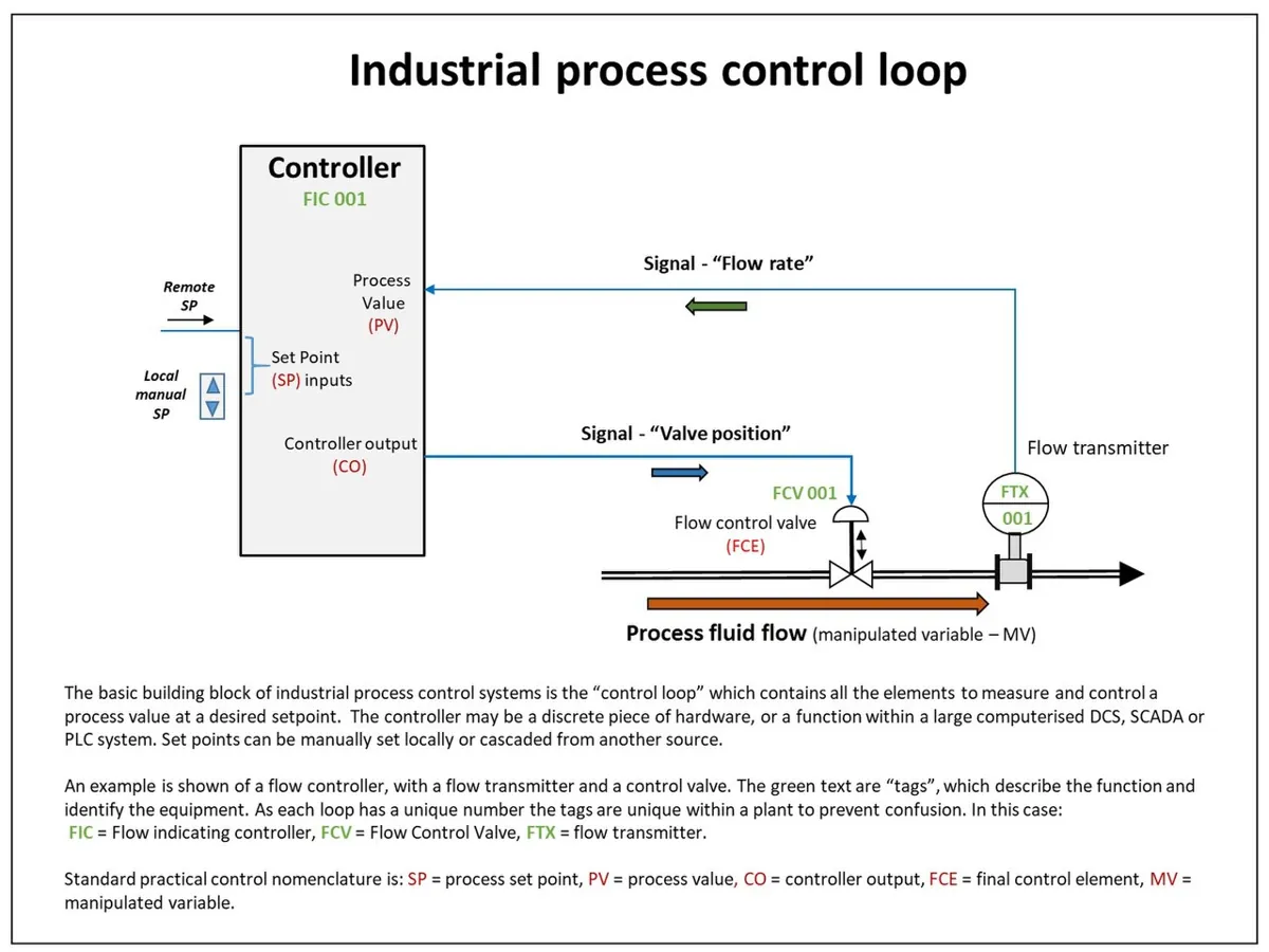
In Lessons 5–7 you met each term alone. P gave speed but left a leftover error and, with a high gain, overshoot. I removed the leftover error but added overshoot. D calmed the overshoot but could not touch the leftover error and amplified noise. Put together, each covers the others’ weakness. *Modern Robotics* (Eq. 11.23) writes the full PID law for a robot joint and calls it a common feedback controller; the Michigan *Control Tutorials* add that PID is widely used because it is easy to understand and quite effective.
By the end of this lesson you will be able to: write PID as one equation and as clean code; build a small, reusable PID class with output limits, a clamped integral and derivative on measurement; compare P, PI, PD and PID on the same joint; read which term does the work at each moment of a move; and run the same PID on the Arduino light keeper.
Concept
How the three terms share the work
u = Kp × e + Ki × ∫ e dt + Kd × de/dt
- P — reacts to the error now (the push).
- I — reacts to the error accumulated so far (the memory).
- D — reacts to how fast the error is changing (the brakes).
- *Modern Robotics* Eq. 11.23: τ = Kp θe + Ki ∫θe dt + Kd θ̇e.
| Mode | Ki | Kd | Peak | Final | Error at 10 s | Settles within ±2° |
|---|---|---|---|---|---|---|
| P | 0 | 0 | 131.90° | 88.75° | 1.25° | 4.53 s |
| PI | 0.002 | 0 | 133.33° | 89.50° | 0.50° (still shrinking) | 3.22 s |
| PD | 0 | 0.008 | 93.89° | 88.75° | 1.25° | 1.20 s |
| PID | 0.002 | 0.008 | 95.35° | 90.07° | −0.07° | 1.34 s |
| PID (Ki too big) | 0.01 | 0.008 | 100.96° | 90.45° | −0.45° | 4.49 s |
PD is the fastest to get close, but stays 1.25° short. PI removes most of the error but swings wildly. PID gets both: small overshoot, quick settling and almost no leftover error. The last row is a warning: with Ki five times bigger, the integral builds up during the rise, so the joint overshoots more and creeps back slowly. More is not always better.
Who does the work, and when?
| Time | Angle | P term | I term | D term | What is happening |
|---|---|---|---|---|---|
| 0.05 s | 2° | 3.52 | 0.01 | −0.60 | P pushes hard; D already braking as speed builds |
| 0.30 s | 42° | 1.92 | 0.04 | −1.48 | Moving fast — D brakes strongly |
| 0.60 s | 84° | 0.26 | 0.06 | −0.67 | Nearly there; P almost gone |
| 1.00 s | 95° | −0.21 | 0.06 | 0.03 | Small overshoot; P pulls back |
| 10 s | 90.07° | −0.003 | 0.053 | 0.000 | At rest: I holds the gravity load (0.05 N·m) |
This table is the whole lesson in one picture. P does the heavy lifting at the start, D acts only while the joint moves, and I quietly takes over the steady load. At rest, P and D are almost zero and the I term carries the 0.05 N·m that gravity needs.
A real PID is more than the formula
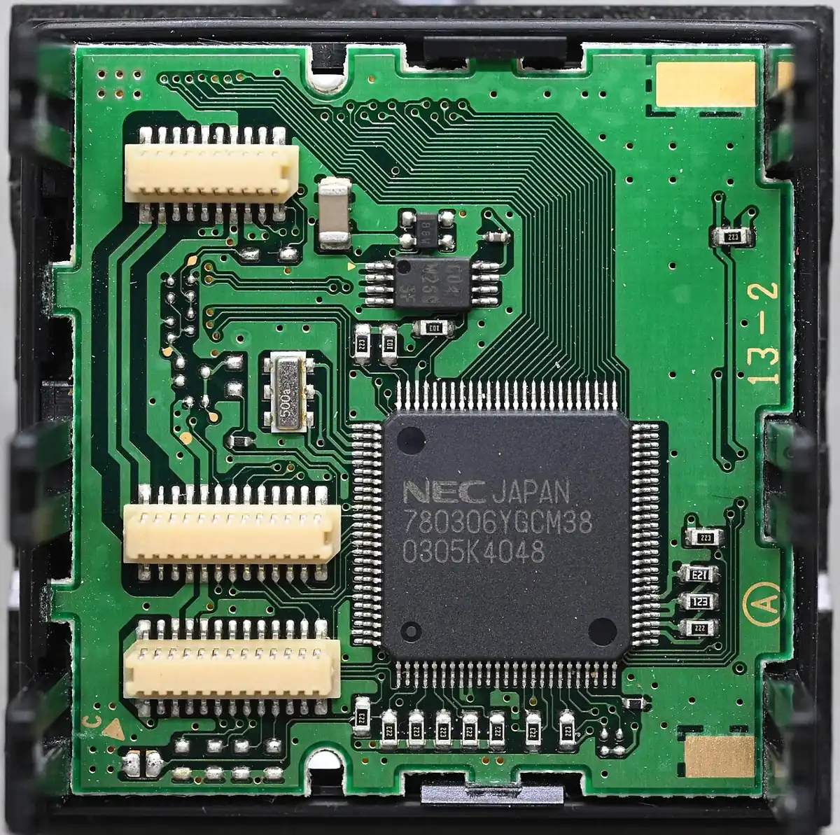
- Output limits — clamp the command to what the actuator can do (±4 N·m here, 0–255 PWM on Arduino).
- Anti-windup — clamp the integral so it cannot exceed the output range (Lesson 6; more in Lesson 11).
- Derivative on measurement — no kick when the setpoint jumps (Lesson 7).
- Fixed loop rate and real dt — so the gains mean the same thing every tick (Lesson 4).
- Logging — print P, I and D separately; you can’t tune what you can’t see.
Visual
Visualise it: P vs PI vs PD vs PID
Switch between **P, PI, PD and PID** on the same plant. Compare overshoot, settling time and leftover error — and see why the full team usually wins.
Interactive · PID visualizer

Setpoint 70° · final θ 69.1° · |SSE| 0.94° · constant load on
Teaching model: Kp↑ snappier (overshoot risk); Ki↑ reduces steady-state error under load; Kd↑ damps the edge.
Code lab
Code lab: a reusable PID class
pid_control.py packs everything into one small PID class with output limits, a clamped integral and derivative on measurement. It then runs P, PI, PD and PID on the same joint and prints who does the work during the PID move. Run it with python3 pid_control.py.
# pid_control.py - putting P, I and D together in one small, reusable PID class.
# Same joint as Lessons 5-7: J*accel = torque - B*speed - LOAD   (angles in degrees)

J, B, LOAD, TAU_MAX = 0.002, 0.004, 0.05, 4.0
SETPOINT, DT, T_END = 90.0, 0.001, 10.0


class PID:
    def __init__(self, kp, ki, kd, out_min, out_max):
        self.kp, self.ki, self.kd = kp, ki, kd
        self.out_min, self.out_max = out_min, out_max
        self.integral = 0.0
        self.prev_meas = None

    def update(self, setpoint, measured, dt):
        error = setpoint - measured
        p = self.kp * error
        # integral, clamped so the I term alone can never exceed the output limits
        self.integral += error * dt
        if self.ki > 0:
            lim = self.out_max / self.ki
            self.integral = max(-lim, min(lim, self.integral))
        i = self.ki * self.integral
        # derivative on MEASUREMENT: no kick when the setpoint jumps
        d_meas = 0.0 if self.prev_meas is None else (measured - self.prev_meas) / dt
        self.prev_meas = measured
        d = -self.kd * d_meas
        out = max(self.out_min, min(self.out_max, p + i + d))
        return out, p, i, d


def run(kp, ki, kd):
    pid = PID(kp, ki, kd, -TAU_MAX, TAU_MAX)
    angle = speed = t = 0.0
    log = []
    while t < T_END:
        torque, p, i, d = pid.update(SETPOINT, angle, DT)
        speed += (torque - B * speed - LOAD) / J * DT
        angle += speed * DT
        t += DT
        log.append((t, angle, p, i, d))
    return log


def settle_time(log, band=2.0):
    last_out = 0.0
    for t, a, *_ in log:
        if abs(SETPOINT - a) > band:
            last_out = t
    return last_out if last_out < T_END - 0.01 else None


print("Same joint, gravity load 0.05 N.m, setpoint 90 deg\n")
print(f"{'mode':>5} {'Kp':>6} {'Ki':>6} {'Kd':>6} {'peak':>9} {'final':>9} {'error':>7} {'settle(+/-2deg)':>16}")
for name, kp, ki, kd in (("P", 0.04, 0, 0), ("PI", 0.04, 0.002, 0),
                         ("PD", 0.04, 0, 0.008), ("PID", 0.04, 0.002, 0.008),
                         ("PID*", 0.04, 0.01, 0.008)):
    log = run(kp, ki, kd)
    peak = max(a for _, a, *_ in log)
    final = log[-1][1]
    st = settle_time(log)
    st_txt = f"{st:.2f} s" if st is not None else "never"
    print(f"{name:>5} {kp:>6} {ki:>6} {kd:>6} {peak:>8.2f}° {final:>8.2f}° {SETPOINT-final:>6.2f}° {st_txt:>16}")

print("PID* = same PID with Ki five times bigger: the integral grows during the rise and causes a slow tail.")
print("\nInside the PID run (Kp 0.04, Ki 0.002, Kd 0.008) - who does the work?")
log = run(0.04, 0.002, 0.008)
print(f"{'t (s)':>6} {'angle':>8} {'P term':>8} {'I term':>8} {'D term':>8}  (N.m)")
for t_pick in (0.05, 0.3, 0.6, 1.0, 2.0, 5.0, 10.0):
    t, a, p, i, d = min(log, key=lambda r: abs(r[0] - t_pick))
    print(f"{t_pick:>6.2f} {a:>7.2f}° {p:>8.3f} {i:>8.3f} {d:>8.3f}")
print("\nP pushes hard at the start, D brakes while the joint moves fast,")
print("and I slowly takes over the 0.05 N.m that gravity needs.")
Output (run with python3 pid_control.py)
Same joint, gravity load 0.05 N.m, setpoint 90 deg

 mode     Kp     Ki     Kd      peak     final   error  settle(+/-2deg)
    P   0.04      0      0   131.90°    88.75°   1.25°           4.53 s
   PI   0.04  0.002      0   133.33°    89.50°   0.50°           3.22 s
   PD   0.04      0  0.008    93.89°    88.75°   1.25°           1.20 s
  PID   0.04  0.002  0.008    95.35°    90.07°  -0.07°           1.34 s
 PID*   0.04   0.01  0.008   100.96°    90.45°  -0.45°           4.49 s
PID* = same PID with Ki five times bigger: the integral grows during the rise and causes a slow tail.

Inside the PID run (Kp 0.04, Ki 0.002, Kd 0.008) - who does the work?
 t (s)    angle   P term   I term   D term  (N.m)
  0.05    2.05°    3.521    0.009   -0.600
  0.30   42.11°    1.923    0.044   -1.476
  0.60   83.58°    0.260    0.059   -0.666
  1.00   95.24°   -0.210    0.057    0.033
  2.00   89.82°    0.007    0.054   -0.003
  5.00   90.09°   -0.003    0.053    0.000
 10.00   90.07°   -0.003    0.053    0.000

P pushes hard at the start, D brakes while the joint moves fast,
and I slowly takes over the 0.05 N.m that gravity needs.Try it: switch between P, PI, PD and PID modes on the same plant. Find the mode that gives small overshoot and zero leftover error.
Interactive · PID visualizer
Setpoint 70° · final θ 69.1° · |SSE| 0.94° · constant load on
Teaching model: Kp↑ snappier (overshoot risk); Ki↑ reduces steady-state error under load; Kd↑ damps the edge.
Simulator
Try it in the simulator
Simulator · Control
PID tuning on a DC-motor position plant
Tune Kp, Ki and Kd, add an actuator limit and anti-windup, and read rise time, overshoot and settling from the step response.
Loading simulator…
Formulas used
- e = r − y
- u = Kp·e + Ki·Σe·Δt − Kd·Δy/Δt
- J·θ̈ + b·θ̇ = K·u − τ_load
- |u| ≤ u_max
- P-only steady-state error with load: e_ss = τ_load / (K·Kp)
Model & limits
Linear DC-motor position model (inertia J, viscous friction b, torque gain K), no backlash or static friction. Teaching values, not a specific motor.
Real world
PID in machines you know
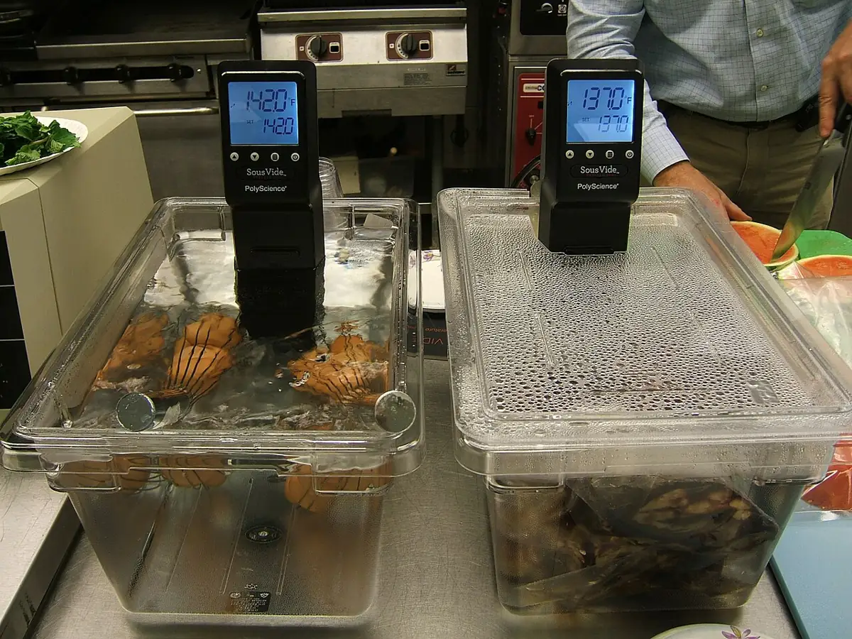
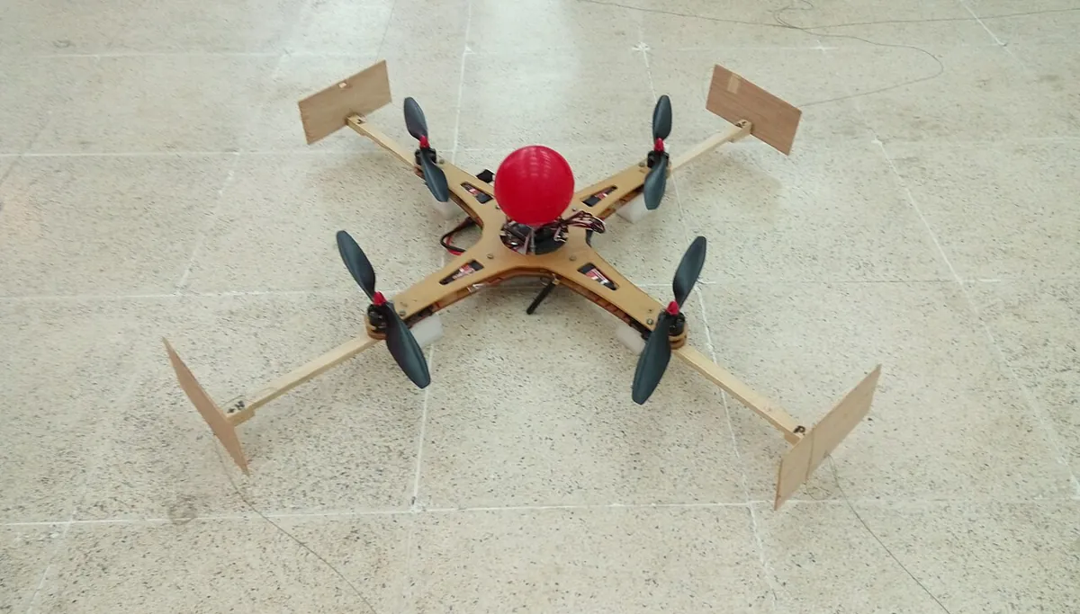
- Robot joints: *Modern Robotics* presents PID (Eq. 11.23) as a common joint feedback controller and even gives pseudocode for it (Figure 11.15).
- 3D printers: Marlin holds hot-end and bed temperatures with PID (Lesson 6).
- Everyday engineering: the *Control Tutorials* note that PID is widely employed because engineers understand it and it works well.
Bench build
Bench build: full PID on the light keeper
The same LED + LDR circuit from Lessons 2–6, now with a small reusable PID struct: output limits 0–255, clamped integral, derivative on measurement and a fixed 100 Hz loop. Open the Serial Plotter and watch the three terms.
Same wiring
Pin 9 → 220 Ω → LED → GND; 5 V → LDR → A0 → 10 kΩ → GND; paper tube around both.
Upload pid_light.ino
Serial Plotter at 115200. You will see setpoint, reading, p_term, i_term, d_term and pwm.
Disturb it
Shade the sensor halfway, then remove the shade. Watch D react to the sudden change and I settle the long-term value.
Turn terms off
Set kd = 0, then ki = 0, then both. Note what each loses.
Change the setpoint
Try SETPOINT 400 and 750. Does the same PID work well at both? Why might it not?
// pid_light.ino - a small, reusable PID "struct" running the LED + LDR light keeper.
// Wiring (same as Lessons 2-6): pin 9 -> 220 ohm -> LED -> GND;  5V -> LDR -> A0 -> 10k -> GND.
// Open Serial Plotter at 115200 to watch setpoint, reading and the P, I and D terms.

struct PID {
  float kp, ki, kd;
  float outMin, outMax;
  float integral;      // stored as I-term output (already multiplied by ki)
  float prevMeas;
  bool first;

  float update(float setpoint, float measured, float dt) {
    float error = setpoint - measured;
    float p = kp * error;
    integral += ki * error * dt;
    integral = constrain(integral, outMin, outMax);          // anti-windup clamp
    float dMeas = first ? 0 : (measured - prevMeas) / dt;   // derivative on measurement
    first = false;
    prevMeas = measured;
    float d = -kd * dMeas;
    lastP = p; lastD = d;
    return constrain(p + integral + d, outMin, outMax);
  }
  float lastP, lastD;
};

const int LED_PIN = 9, SENSOR_PIN = A0;
const int SETPOINT = 600;
const unsigned long PERIOD_MS = 10;          // 100 Hz loop
const float DT = PERIOD_MS / 1000.0;

// kp, ki, kd, outMin, outMax, integral, prevMeas, first
PID light = {0.2, 1.0, 0.002, 0, 255, 0, 0, true};
unsigned long lastTick = 0;

void setup() {
  pinMode(LED_PIN, OUTPUT);
  Serial.begin(115200);
  Serial.println(F("setpoint,reading,p_term,i_term,d_term,pwm"));
}

void loop() {
  if (millis() - lastTick < PERIOD_MS) return;   // fixed loop rate (Lesson 4)
  lastTick = millis();
  int reading = analogRead(SENSOR_PIN);
  int pwm = (int)light.update(SETPOINT, reading, DT);
  analogWrite(LED_PIN, pwm);

  Serial.print(SETPOINT); Serial.print(',');
  Serial.print(reading); Serial.print(',');
  Serial.print(light.lastP, 1); Serial.print(',');
  Serial.print(light.integral, 1); Serial.print(',');
  Serial.print(light.lastD, 1); Serial.print(',');
  Serial.println(pwm);
}Debugging
Debugging a full PID
| Symptom | Likely cause | Fix |
|---|---|---|
| Oscillates and never settles | Kp or Ki too high | Halve Ki, then Kp; add a little Kd |
| Slow tail after a small overshoot | Ki too high — integral stored during the rise | Lower Ki; clamp the integral |
| Buzzing or jittery output | Kd amplifying noise | Lower Kd; filter the derivative (Lesson 12) |
| Sign looks wrong — runs away | Feedback sign or wiring reversed | Check error = setpoint − measured and the sensor direction |
| Gains work at one setpoint but not another | The plant changes with operating point (e.g. LDR is non-linear) | Tune at the working point; consider gain scheduling later |
| Changing loop speed changes everything | dt not used or not fixed | Fixed-rate loop; multiply I by dt and divide D by dt |
Think
Think about it
Think
Priya’s robot arm uses PID on the shoulder. With no load it is perfect. When she adds a 200 g gripper, it still reaches the target, but it overshoots more and takes twice as long to settle. Which term is doing the extra work, and what could she change?
Experiment
Try it in the lab: build your own PID
About 35 minutes with the visualiser, the PID class and the light keeper.
Experiment
Build your own PID
You will need
- PID visualiser (in your browser)
- Your plots from Lessons 5–7
- Optional: `pid_control.py`; Arduino UNO, LED, 220 Ω, LDR, 10 kΩ
Steps
- In the visualiser, compare P, PI, PD and PID on the same plant. Sketch all four on one graph.
- Run `pid_control.py`. Copy the mode table into your notebook.
- Using the order P → D → I, tune your own gains for a peak under 95° and settling under 1.5 s.
- Try your gains with `LOAD = 0.08`. Do they still meet the target?
- Optional bench: run `pid_light.ino`, disturb it, and switch terms off one by one.
Interactive · PID visualizer
Setpoint 70° · final θ 69.1° · |SSE| 0.94° · constant load on
Teaching model: Kp↑ snappier (overshoot risk); Ki↑ reduces steady-state error under load; Kd↑ damps the edge.
Each term fixes a different problem: P speed, I leftover error, D overshoot. Good PID gains balance all three for one plant and one operating point.
Knowledge check
Check your understanding
Knowledge check
1. The full PID law is…
2. In the code lab, which mode gave small overshoot AND almost no leftover error?
3. Why did PD stay 1.25° short?
4. At rest in the PID run, which term carries the gravity load?
5. During the fast rise, the D term is…
6. PID* (Ki = 0.01) settled slowly because…
7. The Control Tutorials’ suggested order for adding terms is…
8. Which is NOT part of a practical PID?
9. Do you always need all three terms?
10. Why print P, I and D separately while tuning?
Mini assignment
Hands-on assignment
Mini assignment
PID team report
Build, test and explain a full PID controller for the simulated joint (and optionally the light keeper).
Deliverables
- Your own PID class (in Python or Arduino) with output limits, clamped integral and derivative on measurement.
- A graph comparing P, PI, PD and PID for your gains.
- A “who does the work” table for your PID, at five moments of a move.
- Your final gains with one paragraph per term explaining its job.
- If you built it: plotter screenshots of `pid_light.ino` during a shade test.
Do this, step by step
- Read
pid_control.py, then run it and copy the P, PI, PD and PID comparison. - Write your own PID class (Python or Arduino) with output limits, a clamped integral and derivative on measurement; test it on the same plant.
- Pick five moments of one move (start, rising, peak, settling, holding) and fill in a “who does the work” table with the P, I and D terms.
- In the PID visualiser switch between P, PI, PD and PID and find the mode with small overshoot and zero leftover error.
- If you have the light keeper: flash
pid_light.ino, shade the LDR, then turn each term off in turn and save a plotter sketch of each. Write one paragraph per term on its job.
Stuck? Hints, one at a time
- Hint 1: Start from
pid_control.py; change only the gains in the mode list. - Hint 2: If the tail is slow, look at the I column — is it overshooting 0.05?
- Hint 3: If the peak is too high, raise Kd before touching Kp.
- Hint 4: For the Arduino struct, remember
first = trueso the first derivative is zero.
Challenges (pick by level)
- 🟢 Easy: Write the job of P, I and D in one line each, in your own words.
- 🟢 Easy: From the inside table, at what time is the D term strongest?
- 🟡 Medium: Add a step change in LOAD at t = 5 s and plot how each term reacts.
- 🟡 Medium: Port the Python
PIDclass to Arduino as a C++ class with areset()method. - 🟠 Hard-ish: Add gravity feedforward (
u += LOAD) and re-tune. How small can Ki become? - 🔴 Hard: Write an automatic search over Kp, Ki and Kd that minimises settling time with peak < 95°. Report the best gains and how long the search took.
- ⚫ Research: Read Modern Robotics 11.4.1 and explain the practical limits it lists for PID on a real joint.
Next step
“Small overshoot, quick settling” needs numbers. In Lesson 9 — Step Response Metrics you learn to measure rise time, overshoot, settling time and steady-state error properly.
Look back: Lesson 7: Derivative Control (D). Next: Lesson 9: Step Response Metrics. Related: Stage 2 — Programming & Python (classes) and Stage 5 L08: Feedback & Closed-Loop Control.
Sources
- Modern Robotics — K. M. Lynch & F. C. Park (preprint PDF) — Sec. 11.4.1, Eq. 11.23: PID as a common feedback controller; Figure 11.15 pseudocode; roles of Kp, Ki, Kd; PD under gravity; Sec. 11.4: feedforward used together with feedback.
- Control Tutorials (University of Michigan) — Introduction: PID Controller Design — effects of each gain; P, PI, PD and PID compared; PID widely employed; general tips for designing a PID controller; keep the controller as simple as possible.
- Marlin Firmware — M303: PID autotune — PID for hot end and heated bed.
- Photos and diagrams: Wikimedia Commons (credits under each image).
Self-attested for now — keep artifacts in your lab notebook.
Complete
Today's goal
0 of 1 done today
Mark this lesson complete when you have worked the experiment, knowledge check, and assignment (even roughly).