
Control Systems & PID · Lesson 07
Derivative Control (D)
Est. 60–75 min
Why
Why a fast joint needs brakes
In Lessons 5 and 6, raising Kp and adding Ki made the joint faster and removed the leftover error — but both added overshoot. The joint reached the target at full speed and swung past it. Derivative control (D) adds a term that depends on how fast the error is changing. When the joint is rushing towards the target, the D term pushes back like a brake. *Modern Robotics* describes it nicely: Kp acts like a virtual spring and Kd like a virtual damper.
By the end of this lesson you will be able to: write the PD law; explain why D reduces overshoot but does not remove the steady-state error (Michigan Control Tutorials); run a Kd sweep and pick a value; show in numbers why D amplifies sensor noise; use “derivative on measurement” to avoid a kick when the setpoint jumps; and wire a small DC gear motor with an encoder through a TB6612FNG driver for a safe PD bench test.
Concept
How the derivative term works — and why it hates noise
P looks at *where* you are (the error now). I looks at *where you have been* (the sum of past error). D looks at *where you are heading* — the rate of change of the error. If the error is shrinking quickly, D reduces the push before you arrive.
u = Kp × e + Kd × de/dt (in code: deriv = (e − e_prev) / dt; u = Kp*e + Kd*deriv)
- Kd = derivative gain. *Modern Robotics* (11.4.1) writes PD control as τ = Kp θe + Kd θ̇e and calls Kd a virtual damper.
| Kd | Peak | Overshoot | Settles within 2% | Final angle |
|---|---|---|---|---|
| 0 (P only) | 131.90° | 48.6 % | 3.78 s | 88.75° |
| 0.002 | 117.72° | 32.6 % | 2.48 s | 88.75° |
| 0.004 | 107.16° | 20.7 % | 1.86 s | 88.75° |
| 0.008 | 93.89° | 5.8 % | 1.34 s | 88.75° |
| 0.016 | 88.75° | 0 % | 1.59 s | 88.75° |
Two things to notice. First, overshoot falls from 48.6 % to 0 as Kd rises — the brakes work. But Kd = 0.016 settles *slower* than 0.008: too much damping makes the joint creep in. Second, the final angle never changes: 88.75° for every Kd. The Michigan *Control Tutorials* table says exactly this — D has no effect on steady-state error. Once the joint stops, de/dt is zero and D contributes nothing. That is why *Modern Robotics* shows a PD joint under gravity resting where Kp × error equals the gravity torque (0.05 ÷ 0.04 = 1.25°), and adds I to remove it.
| When you raise Kd… | Rise time | Overshoot | Settling time | Steady-state error |
|---|---|---|---|---|
| Effect | Small change | Decreases | Decreases | No change |
D’s weakness: noise
A derivative divides a small change by a small time. If the sensor flickers by ±0.2° from one 1 ms sample to the next, that looks like ±200°/s! In our noise test, the torque while “holding” the joint jumped between 0.04 and 0.06 N·m with Kd = 0 — but between −1.54 and +1.58 N·m with Kd = 0.004. On a real motor that means buzzing, heat and wear. Real controllers filter the derivative (Lesson 12).
Derivative on measurement
If you take the derivative of the *error* and the setpoint jumps from 0° to 90° in one tick, de/dt is enormous for that one sample — a “derivative kick” that slams the motor. The common fix is to take the derivative of the *measurement* instead: when the setpoint is constant, −d(measurement)/dt equals de/dt, but a setpoint jump does not cause a spike. pd_motor.ino does exactly this: u = KP*error − KD*speed.
Visual
Visualise it: overshoot vs Kd
Start with a large **Kp** so the response overshoots. Then raise **Kd** and watch the overshoot shrink. Keep going and see the response become sluggish — the sweet spot is in between.
Interactive · PID visualizer

Setpoint 70° · final θ 69.1° · |SSE| 0.94° · constant load on
Teaching model: Kp↑ snappier (overshoot risk); Ki↑ reduces steady-state error under load; Kd↑ damps the edge.
Code lab
Code lab: a Kd sweep — and a noise test
We take the aggressive Kp = 0.04 from Lesson 5 (48.6 % overshoot) and add derivative action for five values of Kd. Then the script adds ±0.2° of random sensor noise and compares the torque with and without D. Run it with python3 pd_control.py.
# pd_control.py - adding DERIVATIVE action to damp overshoot, and what it does with noise.
# Same joint as p_control.py (angles in degrees). Controller (PD): torque = Kp*e + Kd*(de/dt)
import random
J, B, LOAD, TAU_MAX = 0.002, 0.004, 0.05, 4.0
SETPOINT, DT, T_END = 90.0, 0.001, 10.0
KP = 0.04

def run(kd, noise_deg=0.0, seed=1):
    rnd = random.Random(seed)
    angle = speed = 0.0
    prev_e = SETPOINT - angle
    t, log, torques = 0.0, [], []
    while t < T_END:
        measured = angle + rnd.uniform(-noise_deg, noise_deg)
        e = SETPOINT - measured
        de = (e - prev_e) / DT                   # how fast the error is changing
        prev_e = e
        torque = max(-TAU_MAX, min(TAU_MAX, KP * e + kd * de))
        speed += (torque - B * speed - LOAD) / J * DT
        angle += speed * DT
        t += DT
        log.append((t, angle)); torques.append(torque)
    return log, torques

def summary(log):
    final = sum(a for _, a in log[-1000:]) / 1000
    peak = max(a for _, a in log)
    settle = max((t for t, a in log if abs(a - final) > 0.02 * final), default=0.0)
    return final, peak, settle

print(f"Kp = {KP} N.m/deg (lots of overshoot with P alone), setpoint {SETPOINT:.0f} deg\n")
print(f"{'Kd':>6} {'peak':>8} {'overshoot':>10} {'settle 2%':>10} {'final':>8}")
for kd in (0.0, 0.002, 0.004, 0.008, 0.016):
    final, peak, settle = summary(run(kd)[0])
    print(f"{kd:>6} {peak:>7.2f}° {max(0, peak-final)/final*100:>8.1f} % {settle:>8.2f} s {final:>7.2f}°")
print("\nNoise test: sensor noise of +/-0.2 deg, Kd = 0.004")
for kd in (0.0, 0.004):
    _, tq = run(kd, noise_deg=0.2)
    late = tq[-2000:]
    print(f"  Kd={kd}: torque jumps between {min(late):+.2f} and {max(late):+.2f} N.m while 'holding'")
print("Derivative damps overshoot but does not change the steady error - and it amplifies noise.")
Output (run with python3 pd_control.py)
Kp = 0.04 N.m/deg (lots of overshoot with P alone), setpoint 90 deg

    Kd     peak  overshoot  settle 2%    final
   0.0  131.90°     48.6 %     3.78 s   88.75°
 0.002  117.72°     32.6 %     2.48 s   88.75°
 0.004  107.16°     20.7 %     1.86 s   88.75°
 0.008   93.89°      5.8 %     1.34 s   88.75°
 0.016   88.75°      0.0 %     1.59 s   88.75°

Noise test: sensor noise of +/-0.2 deg, Kd = 0.004
  Kd=0.0: torque jumps between +0.04 and +0.06 N.m while 'holding'
  Kd=0.004: torque jumps between -1.54 and +1.58 N.m while 'holding'
Derivative damps overshoot but does not change the steady error - and it amplifies noise.Try it: set a high Kp so the response overshoots, then raise Kd. Watch the overshoot shrink — and find where the response becomes sluggish.
Interactive · PID visualizer
Setpoint 70° · final θ 69.1° · |SSE| 0.94° · constant load on
Teaching model: Kp↑ snappier (overshoot risk); Ki↑ reduces steady-state error under load; Kd↑ damps the edge.
Real world
Damping in machines you know
- Robot joints: *Modern Robotics* treats Kd as a virtual damper — the same idea as a shock absorber, but in software.
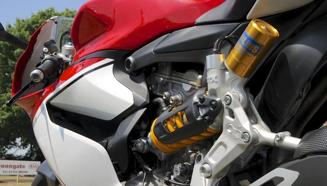
- Vehicle suspension: springs and dampers work as a mechanical PD pair.
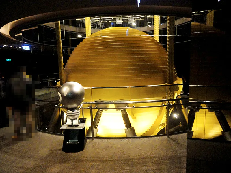
- Buildings: tuned mass dampers in Taipei 101, the Statue of Unity and Delhi Airport’s ATC tower reduce swaying.
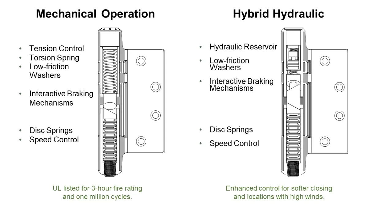
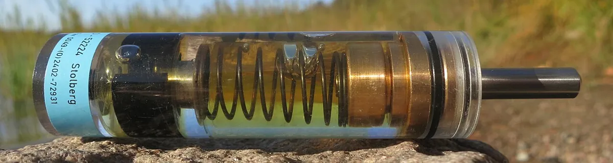
- Door closers: a spring pulls the door shut and a damper controls how fast it swings.
Bench build
Bench build: PD position control of a DC gear motor
Now a real joint: a small DC gear motor with a quadrature encoder, driven by a TB6612FNG dual motor driver. SparkFun’s hookup guide gives its limits: motor supply VM 2.2–13.5 V, logic VCC 2.7–5.5 V, about 1.2 A per channel continuous, and the STBY pin must be pulled high for the outputs to work. Check your motor’s stall current is within the driver’s rating.
Power
Motor battery pack (e.g. 4×AA, 6 V) + → VM, − → GND. Arduino 5 V → driver VCC. Join all grounds: battery, driver and Arduino.
Driver signals
PWMA → pin 5, AIN1 → pin 7, AIN2 → pin 8, STBY → pin 6. Motor wires → A01 and A02.
Encoder
Encoder A → pin 2, B → pin 3 (the UNO’s interrupt pins). Power the encoder as its datasheet says (often 5 V and GND).
Set COUNTS_PER_REV
Find your encoder’s counts per *output-shaft* revolution (encoder counts × gear ratio) and change the constant. Turn the shaft by hand one full turn and check the printout says about 360°.
Test with KD = 0
Shaft free, no arm attached. Open Serial Monitor at 115200 and type 90. Watch the overshoot in the printed angles.
Raise KD
Try 0.05, 0.1, 0.2. Note the peak each time. If the motor starts to buzz or hum, KD is amplifying encoder noise — back off.
// pd_motor.ino - PD position control of a small DC gear motor with a quadrature encoder.
// Driver: TB6612FNG (or similar H-bridge module). The motor gets its OWN supply (e.g. 6 V pack)
// into the driver's VM pin; the driver's VCC logic pin takes 5 V from the Arduino; ALL grounds joined.
// Encoder A -> pin 2, B -> pin 3 (interrupt pins on an UNO), encoder VCC/GND as its datasheet says.
// Type a target in degrees in the Serial Monitor. Start with KD = 0 and watch the overshoot,
// then raise KD step by step. Keep the output shaft free to turn - no arm attached at first.
const int PWMA = 5, AIN1 = 7, AIN2 = 8, STBY = 6;      // TB6612FNG channel A
const int ENC_A = 2, ENC_B = 3;
const float COUNTS_PER_REV = 420.0;   // CHANGE THIS: encoder counts per OUTPUT-shaft revolution
const float KP = 4.0;                 // PWM per degree
const float KD = 0.0;                 // PWM per (degree per second) - try 0.05, 0.1, 0.2
const int PWM_LIMIT = 150;            // keep it gentle while testing
const unsigned long PERIOD_MS = 5;    // 200 Hz loop

volatile long counts = 0;
float target = 0, prevAngle = 0;
unsigned long lastTick = 0;

void onEncA() { counts += (digitalRead(ENC_A) == digitalRead(ENC_B)) ? 1 : -1; }

void drive(int u) {
  u = constrain(u, -PWM_LIMIT, PWM_LIMIT);
  digitalWrite(AIN1, u > 0);
  digitalWrite(AIN2, u < 0);
  analogWrite(PWMA, abs(u));
}

void setup() {
  pinMode(PWMA, OUTPUT); pinMode(AIN1, OUTPUT); pinMode(AIN2, OUTPUT); pinMode(STBY, OUTPUT);
  pinMode(ENC_A, INPUT_PULLUP); pinMode(ENC_B, INPUT_PULLUP);
  attachInterrupt(digitalPinToInterrupt(ENC_A), onEncA, CHANGE);
  digitalWrite(STBY, HIGH);
  Serial.begin(115200);
  Serial.println(F("Type a target angle in degrees (e.g. 90)"));
}

void loop() {
  if (Serial.available()) {
    target = constrain(Serial.parseFloat(), -360, 360);
    while (Serial.available()) Serial.read();
  }
  if (millis() - lastTick < PERIOD_MS) return;
  lastTick = millis();

  noInterrupts(); long c = counts; interrupts();
  float angle = c * 360.0 / COUNTS_PER_REV;
  float error = target - angle;
  float speed = (angle - prevAngle) / (PERIOD_MS / 1000.0);   // derivative on MEASUREMENT
  prevAngle = angle;
  int u = (int)(KP * error - KD * speed);                     // -KD*speed: brake when moving fast
  drive(u);

  static int n = 0;
  if (++n % 20 == 0) {
    Serial.print(F("target=")); Serial.print(target, 1);
    Serial.print(F(" angle=")); Serial.print(angle, 1);
    Serial.print(F(" error=")); Serial.print(error, 1);
    Serial.print(F(" u=")); Serial.println(u);
  }
}Debugging
Debugging the derivative term
| Symptom | Likely cause | Fix |
|---|---|---|
| Motor buzzes or hums while holding | D amplifying sensor noise | Lower Kd; filter the derivative; check encoder wiring |
| Big jolt every time you type a new target | Derivative of the error (derivative kick) | Use derivative on measurement |
| Still overshoots a lot | Kd too small, or speed estimate wrong sign | Raise Kd; check u = KP*error − KD*speed |
| Very slow, creeping arrival | Kd too large (over-damped) | Reduce Kd |
| Motor runs away in one direction | Encoder or motor wired backwards | Swap encoder A/B or the motor leads |
| Nothing moves | STBY low, or no common ground | STBY HIGH; join all grounds |
Think
Think about it
Think
Kabir’s PD joint has no overshoot with Kd = 0.01, but it hums loudly while holding still. When he lowers Kd to 0.002, the hum stops but the arm overshoots by 30 %. Suggest two ways to get both a quiet hold and small overshoot.
Experiment
Try it in the lab: tame the overshoot
About 35 minutes with the visualiser, the Kd sweep and (optionally) the motor bench.
Experiment
Tame the overshoot
You will need
- PID visualiser (in your browser)
- Your Lesson 5 and 6 plots
- Optional: `pd_control.py`; Arduino UNO, TB6612FNG driver, small DC gear motor with encoder, separate motor battery pack
Steps
- In the visualiser, set a high Kp so the response overshoots. Raise Kd in small steps and sketch three responses.
- Run `pd_control.py`. Plot overshoot and settling time against Kd.
- Find the Kd with the shortest settling time. Is it the one with zero overshoot?
- Try the derivative filter in the Play-with-it box. How much do the torque swings fall?
- Optional bench: wire `pd_motor.ino`, set COUNTS_PER_REV, then compare KD = 0 and KD = 0.1 for a 90° move.
Interactive · PID visualizer
Setpoint 70° · final θ 69.1° · |SSE| 0.94° · constant load on
Teaching model: Kp↑ snappier (overshoot risk); Ki↑ reduces steady-state error under load; Kd↑ damps the edge.
D reduces overshoot and can speed up settling, but it leaves the steady-state error alone and amplifies noise. P, I and D each fix one problem and add another — that is why Lesson 8 puts them together.
Knowledge check
Check your understanding
Knowledge check
1. The derivative term responds to…
2. Modern Robotics compares Kp and Kd to…
3. In the code lab, raising Kd from 0 to 0.008 changed the overshoot from…
4. Why was the final angle 88.75° for every Kd?
5. Why did Kd = 0.016 settle slower than Kd = 0.008?
6. In the noise test, adding Kd = 0.004 made the holding torque swing by about…
7. A “derivative kick” happens when…
8. Derivative on measurement means…
9. On the TB6612FNG, which pin must be HIGH for the outputs to work?
10. Where should the motor in the bench build get its power?
Mini assignment
Hands-on assignment
Mini assignment
Overshoot vs Kd report
Show how derivative action changes overshoot, settling and noise, and choose a Kd for this joint.
Deliverables
- A plot of overshoot and settling time against Kd (at least five values).
- Your chosen Kd, with a paragraph on why — mention settling time, noise and steady-state error.
- The noise test: holding-torque swings with and without a derivative filter.
- If you built it: printed angles for a 90° move with KD = 0 and your chosen KD.
- A three-line “D note” for your future self.
Do this, step by step
- Run
python3 pd_control.py(KP= 0.04) and copy the Kd sweep; plot overshoot and settling time against Kd for at least five values. - Run the noise test and write the holding-torque swing with and without the derivative filter.
- Choose your Kd and justify it in one paragraph (settling time, noise, steady-state error).
- In the PID visualiser set a high Kp so it overshoots, then raise Kd until the overshoot is gone, and note where it turns sluggish.
- If you have the motor bench: set
COUNTS_PER_REVfor your motor, runpd_motor.inowithKD= 0.0 for a 90° move, then with your chosen KD; copy both printed angle lists. Write your three-line “D note”.
Stuck? Hints, one at a time
- Hint 1: Keep
KP = 0.04and change onlykd. - Hint 2: The script measures overshoot from the final value: (peak − 88.75) ÷ 88.75 × 100.
- Hint 3: For the filter, keep
d_filtbetween loop steps (outside the per-step calculation). - Hint 4: On the bench, if the angle goes up when the motor is told to go down, swap encoder A and B.
Challenges (pick by level)
- 🟢 Easy: Name three spring + damper pairs in your home or school.
- 🟢 Easy: If the sensor reading changes by 0.5° in 5 ms, what speed does the derivative see?
- 🟡 Medium: Implement derivative on error vs on measurement in
pd_control.py; step the setpoint from 0° to 90° and compare the first-sample torque. - 🟡 Medium: Add a moving-average speed estimate to
pd_motor.inoand compare the hum. - 🟠 Hard-ish: Add Ki = 0.005 to
pd_control.pyand find gains that give under 10 % overshoot and zero final error. - 🔴 Hard: Sweep the derivative filter constant and plot noise swing vs overshoot. Find the best compromise.
- ⚫ Research: Read the Tuned mass damper article and explain how a passive damper differs from our active D term.
Next step
You now have all three ingredients. In Lesson 8 — Combining PID you put P, I and D together in one controller and see how the three terms share the work.
Look back: Lesson 6: Integral Control (I). Next: Lesson 8: Combining PID. Related: Stage 4 L09: PWM & Motor/Servo Control and Stage 5 L06: Sensors & Proprioception (encoders).
Sources
- Modern Robotics — K. M. Lynch & F. C. Park (preprint PDF) — Sec. 11.4.1: PD/PID law; Kp a virtual spring, Kd a virtual damper; PD under gravity rests where Kp θe balances the gravity torque.
- Control Tutorials (University of Michigan) — Introduction: PID Controller Design — D adds damping, reduces overshoot and settling time, no effect on steady-state error.
- SparkFun — TB6612FNG Hookup Guide — VM 2.2–13.5 V, VCC 2.7–5.5 V, 1.2 A continuous per channel, STBY must be high, common ground.
- Wikipedia — Tuned mass damper — Taipei 101’s 660-tonne damper (87th–92nd floors); Statue of Unity’s two 250-tonne dampers; Delhi Airport ATC tower damper.
- Photos: Wikimedia Commons (credits under each image).
Self-attested for now — keep artifacts in your lab notebook.
Complete
Today's goal
0 of 1 done today
Mark this lesson complete when you have worked the experiment, knowledge check, and assignment (even roughly).