
Control Systems & PID · Lesson 11
Saturation, Windup & Safety Limits
Est. 60–75 min
Why
Why real motors say “no”
So far our controllers could ask for any torque they liked (up to a generous ±4 N·m). Real motors have limits: a maximum voltage, current and torque. When the controller asks for more, the actuator saturates — it gives its maximum and no more. *Modern Robotics* lists actuator saturation as one of the practical issues that limit how high you can set the gains. And the integral term makes saturation worse: it keeps adding error while the motor can’t respond — integral windup.
By the end of this lesson you will be able to: explain saturation and windup with numbers from a simulation; compare no protection, an integral clamp and conditional integration; list the layers of safety a real robot needs (output limit, integral limit, position limits, slew limit, stall timeout, hardware stop, fuse); and build a motor sketch with these software limits — while knowing why software is never the last line of defence.
Concept
Saturation, windup and the layers of safety
Saturation
An Arduino PWM output can only go from 0 to 255. A TB6612FNG channel is rated around 1.2 A continuous (SparkFun). A motor has a maximum torque. Whatever your PID calculates, the real output is clipped to these limits. While clipped, the loop is effectively open: changing the gains does nothing until the output comes back inside the limits.
Windup
In windup.py the joint has a weak motor (±0.3 N·m) and a big 0° → 90° step, so the motor is saturated for about 1.6–1.8 s. Look at what the integral does:
| Anti-windup | Peak | Settles within ±2° | Angle at 10 s | Time saturated |
|---|---|---|---|---|
| None | 100.54° | not within 10 s | 94.09° | 1.77 s |
| Clamp I term to ±0.1 N·m | 92.90° | 2.67 s | 90.54° | 1.65 s |
| Conditional integration | 90.73° | 2.00 s | 89.56° | 1.61 s |
With no protection, the integral fills up during the long saturated climb. When the joint reaches 90°, all that stored integral keeps pushing: it overshoots past 100° and is still 4° off after 10 s. *Modern Robotics* describes the fix: integrator anti-windup, which places a limit on how large the error integral is allowed to grow. Two simple versions:
- Clamp: limit the I term to what it actually needs (here a bit more than the 0.05 N·m gravity load).
- Conditional integration: stop adding to the integral while the output is saturated — unless the error would pull the output back inside the limits.
*Modern Robotics* also notes that in practice Ki = 0 for many robot controllers, because stability is paramount. Integral action is powerful, but it must be handled with care.
Layers of safety
| Layer | What it protects against | In this lesson’s sketch |
|---|---|---|
| Output limit | Asking for more than the driver/motor should give | PWM_LIMIT = 150 |
| Integral limit | Windup | I_LIMIT = 60 |
| Position limits | Driving into the end of travel | Target clamped to ±170° |
| Slew limit | Sudden jerks and current spikes | MAX_STEP_PWM = 10 per tick |
| Stall timeout | Motor pushing hard but not moving (jammed, overheating) | Fault after 1.5 s |
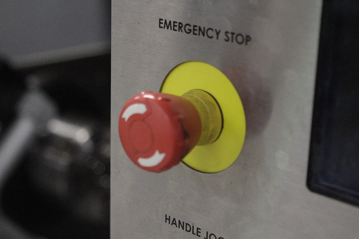
| Hardware stop | Software bugs, crashed controller | Real E-stop that cuts motor power (not in the sketch) |
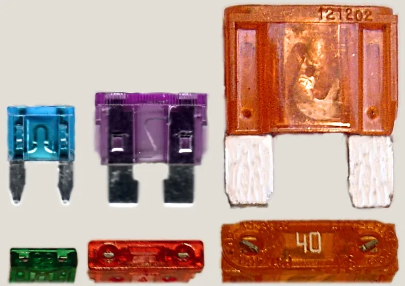
| Fuse / current limit | Short circuits, fires | Fuse in the motor supply line |
Visual
Visualise it: hit the limit
Push the gains and the step size until the output **saturates**. Watch the overshoot that follows — that is the cost of asking for more than the actuator can give.
Interactive · PID tuning lab
Rise time
1.60s
Overshoot
20.5%
|SSE|
2.02°
Settled?
Yes
Recipe: raise Kp until lively but not wild → add Kd to calm overshoot → add Ki to kill SSE under load → back off if it rings.
Code lab
Code lab: watch windup happen
windup.py runs the same PID with three anti-windup choices on a weak motor and prints the peak, settling time, angle at 10 s and how long the motor stayed saturated. Run it with python3 windup.py.
# windup.py - what happens when the controller asks for more than the motor can give.
# Same joint as Lessons 5-10, but with a WEAK motor: torque limited to +/-0.3 N.m,
# so a big 0 -> 90 deg step saturates the motor for a long time.

J, B, LOAD = 0.002, 0.004, 0.05
TAU_MAX = 0.3
SETPOINT, DT, T_END = 90.0, 0.001, 10.0
KP, KI, KD = 0.04, 0.004, 0.008
I_LIMIT = 0.1          # N.m - a bit more than the 0.05 N.m gravity load the I term must hold


def simulate(mode):
    angle = speed = integral = t = 0.0
    prev = angle
    ys, sat_time = [], 0.0
    while t < T_END:
        e = SETPOINT - angle
        d_meas = (angle - prev) / DT
        prev = angle
        p, d = KP * e, -KD * d_meas
        raw = p + KI * integral + d
        torque = max(-TAU_MAX, min(TAU_MAX, raw))
        saturated = torque != raw
        if saturated:
            sat_time += DT
        if mode == "none":
            integral += e * DT                              # keeps growing while saturated
        elif mode == "clamp":
            integral = max(-I_LIMIT / KI, min(I_LIMIT / KI, integral + e * DT))   # I term within +/-I_LIMIT
        elif mode == "conditional":
            # only integrate when NOT saturated, or when the error would pull the output back
            if not saturated or (raw > TAU_MAX and e < 0) or (raw < -TAU_MAX and e > 0):
                integral += e * DT
        speed += (torque - B * speed - LOAD) / J * DT
        angle += speed * DT
        t += DT
        ys.append(angle)
    return ys, sat_time


def report(ys):
    final = sum(ys[-200:]) / 200
    peak = max(ys)
    settle = 0.0
    for i, y in enumerate(ys):
        if abs(y - SETPOINT) > 2.0:
            settle = (i + 1) * DT
    return peak, settle, final


print(f"Weak motor: torque limit +/-{TAU_MAX} N.m. PID Kp={KP} Ki={KI} Kd={KD}, step 0 -> 90 deg\n")
print(f"{'anti-windup':>12} {'peak':>9} {'settle(+/-2deg)':>16} {'final':>8} {'time saturated':>15}")
for mode in ("none", "clamp", "conditional"):
    ys, sat = simulate(mode)
    peak, settle, final = report(ys)
    st = f"{settle:.2f} s" if settle < T_END - 0.01 else "not in 10 s"
    print(f"{mode:>12} {peak:>8.2f}° {st:>16} {final:>7.2f}° {sat:>13.2f} s")
print("\nWithout protection the integral fills up while the motor is maxed out,")
print("then pushes the joint past the target and takes a long time to unwind.")
print("Clamping the I term or conditional integration keeps it sensible.")
Output (run with python3 windup.py)
Weak motor: torque limit +/-0.3 N.m. PID Kp=0.04 Ki=0.004 Kd=0.008, step 0 -> 90 deg

 anti-windup      peak  settle(+/-2deg)    final  time saturated
        none   100.54°      not in 10 s   94.09°          1.77 s
       clamp    92.90°           2.67 s   90.54°          1.65 s
 conditional    90.73°           2.00 s   89.56°          1.61 s

Without protection the integral fills up while the motor is maxed out,
then pushes the joint past the target and takes a long time to unwind.
Clamping the I term or conditional integration keeps it sensible.Try it: use high gains and a big step so the output hits its limit. Watch the overshoot that follows — then make the step smaller and compare.
Interactive · PID tuning lab
Rise time
1.60s
Overshoot
20.5%
|SSE|
2.02°
Settled?
Yes
Recipe: raise Kp until lively but not wild → add Kd to calm overshoot → add Ki to kill SSE under load → back off if it rings.
Real world
Limits and safety in machines you know
- CNC machines and robots: emergency stops that remove power, plus software limits on position and speed.
- Vehicles: fuses protect every circuit; a blown fuse is a limit doing its job.
- Robot controllers: *Modern Robotics* notes that many robot controllers set Ki = 0, and those that use it add anti-windup.
- Motor drivers: have current and voltage ratings — the TB6612FNG is about 1.2 A per channel continuous.
Bench build
Bench build: a motor loop with safety limits
Same hardware as Lesson 7 (DC gear motor with encoder, TB6612FNG driver, separate motor supply), plus a push button. safe_motor.ino adds an output limit, integral limit, position limits, slew limit, a stall timeout and a STOP button that switches the driver to standby.
Power with a fuse
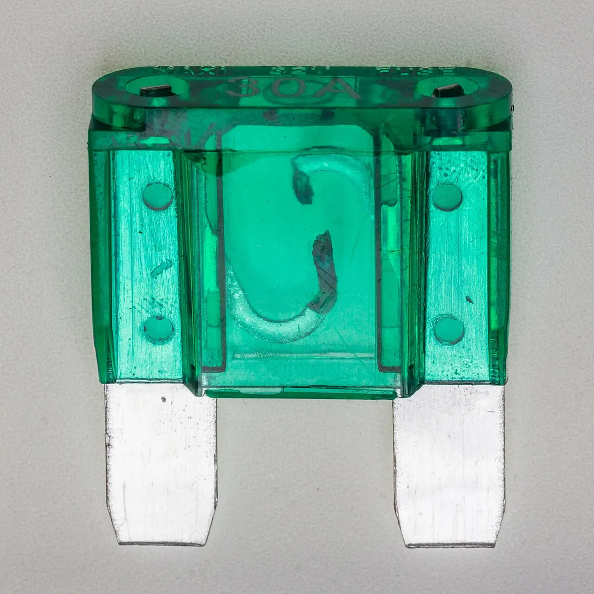
Put an inline fuse suited to your motor and wiring in the positive lead from the motor battery to VM. Join all grounds.
Wire as Lesson 7
PWMA 5, AIN1 7, AIN2 8, STBY 6; encoder A 2, B 3. Set COUNTS_PER_REV for your motor.
Add the STOP button
Push button between pin 4 and GND (the sketch uses the internal pull-up).
Test each limit
Type 500 → the target is clamped to 170. Hold the shaft gently with a cloth → after 1.5 s the stall fault stops the motor. Press STOP → fault.
Watch the I term
Type a big move and read
i=in the printout. It never goes past ±60.
// safe_motor.ino - PID position control of a DC gear motor with SAFETY LIMITS.
// Same hardware as pd_motor.ino (Lesson 7): TB6612FNG driver, motor on its OWN supply into VM,
// driver VCC from Arduino 5 V, all grounds joined, encoder A -> pin 2, B -> pin 3.
// NEW: a normally-open push button from pin 4 to GND acts as a software STOP (it is NOT a
// certified emergency stop - for real machines the E-stop must cut motor power in hardware).
const int PWMA = 5, AIN1 = 7, AIN2 = 8, STBY = 6, ENC_A = 2, ENC_B = 3, STOP_BTN = 4;
const float COUNTS_PER_REV = 420.0;     // CHANGE THIS for your motor (output-shaft counts)
const float KP = 4.0, KI = 2.0, KD = 0.1;
const int   PWM_LIMIT = 150;            // 1. output limit
const float I_LIMIT = 60.0;             // 2. integral (anti-windup) limit, in PWM units
const float MIN_DEG = -170, MAX_DEG = 170;   // 3. soft position limits for the target
const int   MAX_STEP_PWM = 10;          // 4. slew limit: max PWM change per 5 ms tick
const unsigned long STALL_MS = 1500;    // 5. stall timeout: big output but no movement
const unsigned long PERIOD_MS = 5;
const float DT = PERIOD_MS / 1000.0;

volatile long counts = 0;
float target = 0, prevAngle = 0, iTerm = 0;
int lastPwm = 0;
bool faulted = false;
unsigned long lastTick = 0, stallSince = 0;

void onEncA() { counts += (digitalRead(ENC_A) == digitalRead(ENC_B)) ? 1 : -1; }

void drive(int u) {
  digitalWrite(AIN1, u > 0);
  digitalWrite(AIN2, u < 0);
  analogWrite(PWMA, abs(u));
}

void fault(const __FlashStringHelper *why) {
  faulted = true;
  drive(0);
  digitalWrite(STBY, LOW);               // driver outputs off
  Serial.print(F("FAULT: ")); Serial.println(why);
  Serial.println(F("Fix the cause, then press the Arduino reset button."));
}

void setup() {
  pinMode(PWMA, OUTPUT); pinMode(AIN1, OUTPUT); pinMode(AIN2, OUTPUT); pinMode(STBY, OUTPUT);
  pinMode(ENC_A, INPUT_PULLUP); pinMode(ENC_B, INPUT_PULLUP); pinMode(STOP_BTN, INPUT_PULLUP);
  attachInterrupt(digitalPinToInterrupt(ENC_A), onEncA, CHANGE);
  digitalWrite(STBY, HIGH);
  Serial.begin(115200);
  Serial.println(F("Type a target angle in degrees (limited to -170..170)"));
}

void loop() {
  if (faulted) return;
  if (digitalRead(STOP_BTN) == LOW) { fault(F("stop button pressed")); return; }
  if (Serial.available()) {
    target = constrain(Serial.parseFloat(), MIN_DEG, MAX_DEG);
    while (Serial.available()) Serial.read();
  }
  if (millis() - lastTick < PERIOD_MS) return;
  lastTick = millis();

  noInterrupts(); long c = counts; interrupts();
  float angle = c * 360.0 / COUNTS_PER_REV;
  float error = target - angle;
  float speed = (angle - prevAngle) / DT;
  prevAngle = angle;

  iTerm = constrain(iTerm + KI * error * DT, -I_LIMIT, I_LIMIT);
  int u = (int)constrain(KP * error + iTerm - KD * speed, -PWM_LIMIT, PWM_LIMIT);
  u = constrain(u, lastPwm - MAX_STEP_PWM, lastPwm + MAX_STEP_PWM);   // gentle changes only
  lastPwm = u;

  // stall check: pushing hard but the shaft is not moving -> stop before something overheats
  if (abs(u) > PWM_LIMIT * 0.8 && fabs(speed) < 5.0) {
    if (stallSince == 0) stallSince = millis();
    if (millis() - stallSince > STALL_MS) { fault(F("stall - output high but no movement")); return; }
  } else {
    stallSince = 0;
  }
  drive(u);

  static int n = 0;
  if (++n % 20 == 0) {
    Serial.print(F("target=")); Serial.print(target, 1);
    Serial.print(F(" angle=")); Serial.print(angle, 1);
    Serial.print(F(" u=")); Serial.print(u);
    Serial.print(F(" i=")); Serial.println(iTerm, 1);
  }
}Debugging
Debugging limits and faults
| Symptom | Likely cause | Fix |
|---|---|---|
| Big overshoot after long moves | Integral windup | Clamp the I term or use conditional integration |
| Stall fault on every start | Slew limit too small or stall threshold too strict | Check speed units; raise MAX_STEP_PWM slightly |
| Motor never reaches the target | PWM_LIMIT too low for the load | Raise it carefully, within the driver rating |
| Fault message but motor still twitches | STBY not wired to pin 6 | Check the STBY wire |
| Fuse blows when starting | Stall current too high for the fuse | Check motor and fuse ratings; add the slew limit |
Think
Think about it
Think
Priya’s arm uses PID with Ki > 0. When she presses a software STOP (output set to 0) for 10 s while the target is still far away, and then releases it, the arm leaps. Explain why, and suggest two fixes.
Experiment
Try it in the lab: protect the loop
About 35 minutes with the tuning lab, the windup simulation and (optionally) the safe motor bench.
Experiment
Protect the loop
You will need
- PID tuning lab (in your browser)
- `windup.py`
- Optional: Arduino UNO, TB6612FNG, DC gear motor with encoder, battery pack, inline fuse, push button
Steps
- In the tuning lab, make the output saturate with a big step. Sketch the response.
- Run `windup.py`. Copy the table; explain each row in one sentence.
- Change `TAU_MAX` and `SETPOINT` to find when windup stops mattering.
- List the safety layers your own arm project needs, from software to hardware.
- Optional bench: test every limit in `safe_motor.ino` one by one, and log what happened.
Interactive · PID tuning lab
Rise time
1.60s
Overshoot
20.5%
|SSE|
2.02°
Settled?
Yes
Recipe: raise Kp until lively but not wild → add Kd to calm overshoot → add Ki to kill SSE under load → back off if it rings.
Saturation is normal; windup is avoidable. Software limits make a loop well-behaved; hardware limits make it safe.
Knowledge check
Check your understanding
Knowledge check
1. Actuator saturation means…
2. Integral windup happens because…
3. In windup.py, with no protection the joint…
4. Modern Robotics describes integrator anti-windup as…
5. Conditional integration means…
6. According to Modern Robotics, many robot controllers in practice use…
7. A slew limit protects against…
8. Why does safe_motor.ino have a stall timeout?
9. Why is the sketch’s STOP button not a real emergency stop?
10. A fuse in the motor supply line…
Mini assignment
Hands-on assignment
Mini assignment
Safety layers plan
Show windup with numbers, fix it, and design the safety layers for your own arm.
Deliverables
- The windup table for at least two motor strengths (TAU_MAX values), with a sentence on each.
- Your own anti-windup choice for the arm and why.
- A safety-layers table for your arm: output, integral, position, slew, stall, hardware stop, fuse — with values.
- If you built it: a test log showing each limit in `safe_motor.ino` working.
- One paragraph: what would happen if the Arduino crashed mid-move, and what protects you then?
Do this, step by step
- Run
python3 windup.py(TAU_MAX= 0.3,I_LIMIT= 0.1) and copy the table; run again with a stronger and a weakerTAU_MAXand write one sentence for each. - Pick an anti-windup method for your arm (clamp or conditional integration) and say why.
- Fill in a safety-layers table for your arm with values: output limit, integral limit, position limits, slew limit, stall timeout, hardware stop, fuse.
- In the PID tuning lab widget use high gains and a big step, watch the saturated overshoot, then repeat with a smaller step.
- If you have the motor bench: fit the inline fuse and STOP button, flash
safe_motor.ino, and test each limit one at a time (soft limits ±170°,PWM_LIMIT= 150, STOP) — log each result. Then answer: what protects you if the Arduino crashes mid-move?
Stuck? Hints, one at a time
- Hint 1: Saturation time in the output tells you how long windup had to build.
- Hint 2: A good I clamp is a bit more than the steady load the integral must hold.
- Hint 3: For the hardware stop, think about what removes power to the motor, not what tells the code to stop.
- Hint 4: Check the driver’s rating (SparkFun: about 1.2 A per channel) against your motor’s stall current.
Challenges (pick by level)
- 🟢 Easy: Name three limits in a ceiling fan, a lift or a scooter.
- 🟢 Easy: Explain windup to a friend using the flyover story.
- 🟡 Medium: Add a “saturated” column to the printout of
safe_motor.ino. - 🟡 Medium: Implement back-calculation anti-windup in
windup.py(reduce the integral by the amount the output was clipped) and compare. - 🟠 Hard-ish: Add a watchdog to
safe_motor.inothat stops the motor if no new target arrives for 10 s. - 🔴 Hard: Simulate a sensor failure (angle stops updating) and design a check that detects it.
- ⚫ Research: Read Modern Robotics 11.4.1 on choosing Ki and explain why Ki has both a lower and an upper bound.
Next step
D amplified noise in Lesson 7, and real sensors are noisy. In Lesson 12 — Filtering Noisy Feedback you learn to smooth measurements without making the loop slow.
Look back: Lesson 10: Tuning Intuition. Next: Lesson 12: Filtering Noisy Feedback. Related: Stage 5 L13: Safety, Limits & Operating Envelope and Stage 4 L05: Capacitors & Power Stability.
Sources
- Modern Robotics — K. M. Lynch & F. C. Park (preprint PDF) — Sec. 11.4.1: practical limits on gains include actuator saturation and chattering; in practice Ki = 0 for many robot controllers; integrator anti-windup limits how large the error integral can grow.
- Control Tutorials (University of Michigan) — Introduction: PID Controller Design — implementation challenges include control saturation, integrator wind-up and noise amplification.
- SparkFun — TB6612FNG Hookup Guide — motor supply and logic ranges, about 1.2 A continuous per channel, STBY pin.
- Photos: Wikimedia Commons (credits under each image).
Self-attested for now — keep artifacts in your lab notebook.
Complete
Today's goal
0 of 1 done today
Mark this lesson complete when you have worked the experiment, knowledge check, and assignment (even roughly).