
Control Systems & PID · Lesson 01
Why Robots Need Control
Est. 50–65 min
Why
Why a perfect plan still misses the target
A robot lives in the real world, and the real world never stays the same. Batteries sag, loads change, friction grows, wind blows, floors slope. A program that only *plays a plan* — “run the motor for 2 seconds” — is correct only on the day the plan was written. Control is the habit of measuring, comparing with what you wanted, and correcting — again and again, many times a second.
Lynch and Park’s *Modern Robotics* textbook puts it in one line: feedback control uses position, velocity and force sensors to measure the actual behaviour of the robot, compares it with the desired behaviour, and modulates the control signals sent to the actuators — and feedback is used in nearly all robot systems. In Stage 5 (Lesson 8) you met open and closed loops. In this stage you learn to *design* them: P, I and D, how to read a response, how to tune, and how to stay safe when the motor saturates.
By the end of this lesson you will be able to: list the everyday disturbances that break open-loop plans; explain control as measure → compare → correct → repeat; describe what a “good” response looks like (fast, little overshoot, little leftover error); run a simulation that shows plan vs feedback under four conditions; and feel a hobby servo’s feedback loop with your own fingers.
Concept
What “control” means for a robot joint
Think of filling a steel tumbler from the water filter at home. You don’t calculate “open the tap for 6.3 seconds”. You *watch* the water, slow down near the top and stop at the right level. If the pressure drops, you simply wait a little longer — without thinking. Your eyes are the sensor, your brain does the comparing, your hand on the tap is the actuator. That is a control loop, and you have run thousands of them today already.
The four-word definition
| Step | What happens | Robot-joint example |
|---|---|---|
| Measure | A sensor reads what is really happening | Potentiometer or encoder says the joint is at 72° |
| Compare | Subtract it from what you wanted | Error = 90° − 72° = 18° |
| Correct | Turn the error into a command | “Error is big and positive → turn forward, fast” |
| Repeat | Do it again, many times a second | Every 10 ms, until the error is tiny |
error θe(t) = θd(t) − θ(t)
- θd = desired (target) joint angle, θ = measured joint angle. This is exactly how *Modern Robotics* (Section 11.2) defines joint error. The job of the controller is to make θe shrink to zero, or to a small value, as time goes on.
What breaks a plan? Disturbances and surprises
| Problem | What it does to the joint | Who notices? |
|---|---|---|
| Battery at 80% | Motor runs slower for the same command | Only a sensor |
| Heavier load / gravity | Pulls the joint back, especially when the arm is stretched out | Only a sensor |
| Friction, dust, cold grease | Small commands do nothing; motion is jerky | Only a sensor |
| Someone bumps the arm | Joint is pushed off its path | Only a sensor |
| Wrong model | Your “45°/s” estimate was never exactly right | Only a sensor |
Notice the last column. Every one of these is invisible to a program that never measures. That is why the University of Michigan’s *Control Tutorials* describe cruise control as a feedback system: its purpose is to hold a constant speed despite disturbances such as wind or road grade, by measuring the speed, comparing it with the desired speed and automatically adjusting the throttle.
What does “good control” look like?
*Modern Robotics* describes a good error response with three simple wishes. Keep them in your notebook — every lesson in this stage comes back to them.
- Little or no steady-state error — after things settle, the joint is really at the target, not 2° short.
- Little or no overshoot — it doesn’t swing past the target and come back.
- Short settling time — it gets there and calms down quickly (the book uses the time to stay within 2%).
These wishes fight each other. Push harder and you get there faster, but you overshoot more. The *Control Tutorials* PID page says the same about proportional gain: raising it makes the system react more quickly, but tends to overshoot more, and it reduces — but does not eliminate — the steady-state error. Most of control engineering is choosing a sensible balance.
Your hobby servo already has a loop inside
SparkFun’s servo tutorial explains it neatly: a servomechanism is a device that uses feedback. Inside a hobby servo, a potentiometer on the output shaft senses the position; the electronics measure the width of the incoming pulse (1–2 ms, repeated every 20 ms) and drive the motor until the potentiometer matches the pulse. So servo.write(90) is not a plan — it is a setpoint handed to a small closed loop. In the bench build you will switch that loop on and off and feel the difference.
Visual
Visualise it: plan vs feedback
Switch between **open loop** and **closed loop**, then add a disturbance. In open loop the output drifts and nobody reacts; in closed loop the sensor notices and the controller pulls the output back towards the setpoint.
Interactive · Control loop explorer

Mode
Closed
θ final
61.6°
Error
-1.6°
Closed-loop uses error = setpoint − feedback. Open-loop ignores feedback — load disturbances leave steady-state error.
Code lab
Code lab: the same move, four different days
The script moves a joint from 0° to 90°. The open-loop version plays the plan: 45°/s for 2 s. The closed-loop version measures the angle every 10 ms and commands speed = Kp × error. We try both on an ideal day, with a tired battery, with a heavy load and with sticky friction. Run it with python3 why_control.py.
# why_control.py - why a robot joint needs feedback.
# A joint must move from 0 deg to 90 deg. The OPEN-LOOP plan says: "run at 45 deg/s for 2 s".
# The CLOSED-LOOP version measures the angle every 10 ms and commands speed = KP * error.
# We test both against three everyday problems: a heavy load, a tired battery and sticky friction.

DT = 0.01          # 10 ms control tick
T_END = 3.0        # watch for 3 s
TARGET = 90.0      # deg
PLAN_SPEED = 45.0  # deg/s, open-loop plan: 45 deg/s x 2 s = 90 deg
KP = 6.0           # 1/s, proportional gain for the closed loop
MAX_SPEED = 90.0   # deg/s, the motor cannot go faster than this

def joint_speed(cmd, case):
    """What the real joint does with a speed command (the 'plant')."""
    cmd = max(-MAX_SPEED, min(MAX_SPEED, cmd))
    if case == "battery at 80%":
        return 0.8 * cmd              # everything 20% slower
    if case == "heavy load":
        return cmd - 6.0              # gravity drags the joint back by 6 deg/s
    if case == "sticky friction":
        return 0.0 if abs(cmd) < 8.0 else cmd - 4.0 * (1 if cmd > 0 else -1)
    return cmd                        # "ideal lab day"

def run(case, closed):
    angle, t = 0.0, 0.0
    while t < T_END - 1e-9:
        if closed:
            cmd = KP * (TARGET - angle)          # measure -> error -> correct
        else:
            cmd = PLAN_SPEED if t < 2.0 else 0.0  # play the plan, never look
        angle += joint_speed(cmd, case) * DT
        t += DT
    return angle

cases = ["ideal lab day", "battery at 80%", "heavy load", "sticky friction"]
print(f"Target {TARGET:.0f} deg. Open loop = 45 deg/s for 2 s. Closed loop = KP {KP:g} x error.\n")
print(f"{'case':<17}{'open-loop end':>15}{'error':>8}{'closed-loop end':>18}{'error':>8}")
for c in cases:
    o, k = run(c, False), run(c, True)
    print(f"{c:<17}{o:>13.1f} deg{round(TARGET-o,1)+0.0:>7.1f}{k:>16.1f} deg{round(TARGET-k,1)+0.0:>7.1f}")
print("\nOpen loop is perfect only on the ideal day. Feedback shrinks every error,")
print("but simple P control still leaves a little error under a steady load or friction.")
Output (run with python3 why_control.py)
Target 90 deg. Open loop = 45 deg/s for 2 s. Closed loop = KP 6 x error.

case               open-loop end   error   closed-loop end   error
ideal lab day             90.0 deg    0.0            90.0 deg    0.0
battery at 80%            72.0 deg   18.0            90.0 deg    0.0
heavy load                72.0 deg   18.0            89.0 deg    1.0
sticky friction           82.0 deg    8.0            88.7 deg    1.3

Open loop is perfect only on the ideal day. Feedback shrinks every error,
but simple P control still leaves a little error under a steady load or friction.
Try it: give the joint a target, add load and watch the controller fight to hold it.
Interactive · Robot joint controller · Capstone target 90°
θ now
0.0°
t
0.0s
Rise
1.75s
Overshoot
18.2%
|SSE|
1.94°
Capstone gate: |SSE| < 3°, overshoot < 25%, rise < 3.5s under load — PASS
Real world
Control is hiding inside every good machine
- Cars: cruise control measures speed and adjusts the throttle to hold it on hills and in wind (University of Michigan Control Tutorials).
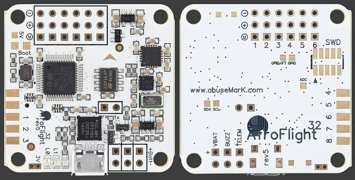
- Drones: a multicopter is unstable without its flight controller constantly correcting the motor speeds.
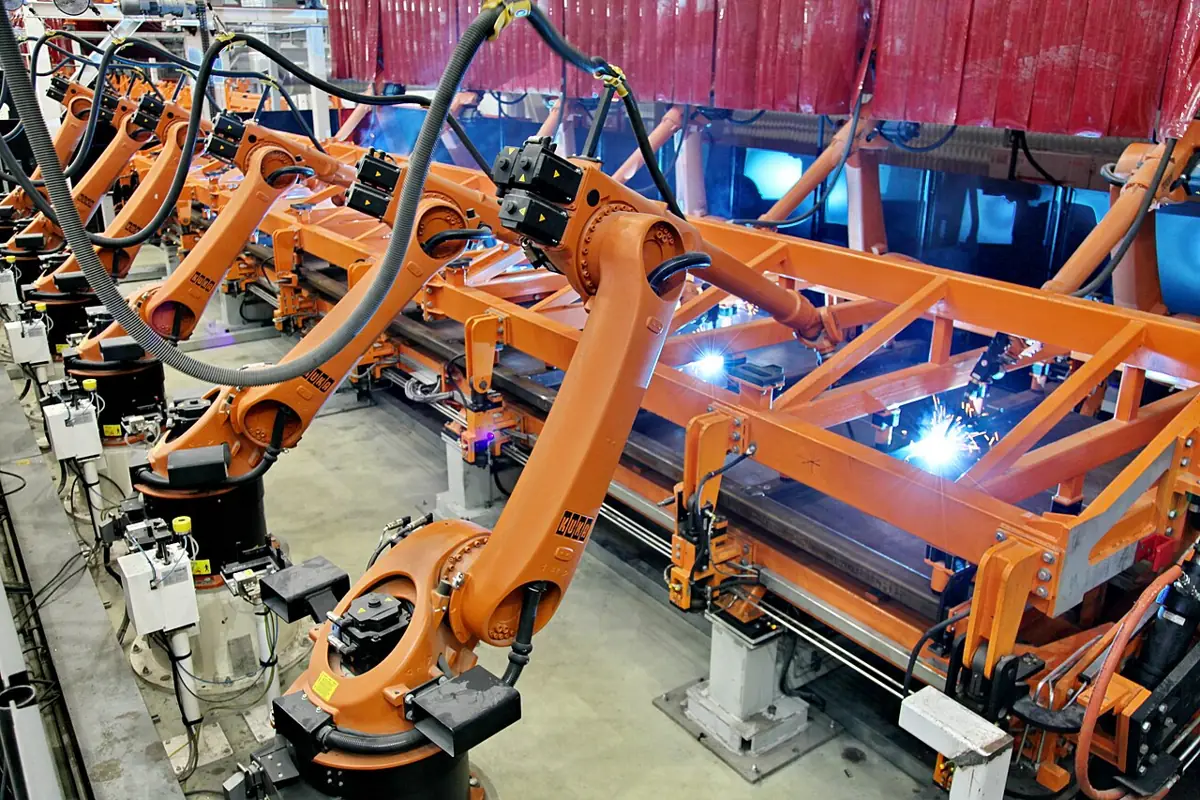
- Factory arms: every joint runs feedback on its own position sensor; *Modern Robotics* notes that a motor amplifier often runs its own inner current loop too, because current sets torque.
- Hobby servos: a potentiometer inside closes the position loop (SparkFun).
- Your home: a water-tank float valve, a fridge thermostat, an iron’s temperature control — all measure and correct.
Bench build
Bench build: feel a feedback loop with your fingers
This five-minute build lets you *feel* the difference between a joint with feedback and one without. For 5 seconds the servo gets a 90° command and its internal loop holds the horn. For the next 5 seconds the Arduino stops sending pulses. Push the horn gently in each phase.
Gather parts
Arduino UNO, one hobby servo (SG90 or MG90S size is fine), a 5–6 V supply for the servo (4×AA pack or a 5 V 2 A adapter), jumper wires.
Wire the signal
Servo signal (orange/yellow/white) → Arduino pin 9.
Wire the power
Servo red → +5–6 V of the separate supply. Servo brown/black → supply GND. Then join supply GND to Arduino GND with one wire — a common ground is needed for the signal to make sense.
Upload and open Serial Monitor
Upload
servo_hold_test.ino, set the monitor to 115200 baud.Push gently in both phases
In FEEDBACK ON, push the horn a little with one finger: it pushes back and returns to 90°. In FEEDBACK OFF, push again. Most analog servos go limp; some digital servos keep holding — write down what yours does.
// servo_hold_test.ino - feel feedback with your own fingers.
// For 5 s the servo receives a 90-degree command and its internal loop HOLDS the horn:
// push it gently and it pushes back. For the next 5 s we stop sending pulses (detach):
// most analog hobby servos go limp - nobody is comparing any more. (Some digital servos
// keep holding their last position; note what yours does.)
// Signal on pin 9. Servo power from a separate 5-6 V supply; supply GND joined to Arduino GND.
#include <Servo.h>

Servo joint;
const int SERVO_PIN = 9;
const int HOLD_ANGLE = 90;

void setup() {
  Serial.begin(115200);
  Serial.println(F("servo_hold_test: push the horn gently in each phase"));
}

void loop() {
  joint.attach(SERVO_PIN);
  joint.write(HOLD_ANGLE);
  Serial.println(F("FEEDBACK ON : command 90 deg - the servo resists you"));
  delay(5000);

  joint.detach();                 // no more pulses: no setpoint to compare against
  Serial.println(F("FEEDBACK OFF: no pulses - most analog servos go limp"));
  delay(5000);
}Debugging
Debugging: when the robot “worked yesterday”
| Symptom | Likely cause | What to do |
|---|---|---|
| Timed move falls short today | Battery lower, load heavier or more friction | Measure the joint angle; close the loop instead of changing the delay |
| Arm sags slowly after reaching the target | Gravity load, no holding correction | Feedback must keep running after the move, not only during it |
| Servo jitters when holding | Noisy power or signal, weak common ground | Separate supply, short ground wire, capacitor across the servo supply (Stage 4) |
| Servo resets the Arduino when it moves | Servo current dips the Arduino’s supply | Power the servo separately; never from a pin |
| Closed loop is still a bit short | P control under steady load or friction | Normal for P only — the integral term (Lesson 6) removes it |
Think
Think about it
Think
Meera says: “My robot car drives straight because I set both motors to exactly the same PWM value.” On the classroom floor it drifts left within two metres. Explain why equal commands do not give equal motion, and what feedback she could add.
Experiment
Try it in the lab: break the plan, keep the loop
About 30 minutes with the explorer, the script and — if you have a servo — the bench test.
Experiment
Break the plan, keep the loop
You will need
- Control loop explorer (runs in your browser)
- Notebook and pencil
- Optional: `why_control.py`; Arduino UNO, hobby servo, separate 5–6 V supply
Steps
- In the explorer, set a setpoint and switch to **open loop**. Add a disturbance. Write down what happens to the output.
- Switch to **closed loop** and repeat with the same disturbance. Write down the difference.
- Run `why_control.py`. Copy the table into your notebook and circle the worst open-loop case.
- Change `KP` to 2, 6 and 20. For the heavy-load case, write Kp vs final error. Check that the error is roughly 6 ÷ Kp.
- Optional bench: run `servo_hold_test.ino` and describe in one sentence how the horn felt with and without feedback.
Interactive · Control loop explorer
Mode
Closed
θ final
61.6°
Error
-1.6°
Closed-loop uses error = setpoint − feedback. Open-loop ignores feedback — load disturbances leave steady-state error.
Open loop is fine only when the world matches your plan. Feedback keeps working when the battery, load or friction changes — though simple P control can leave a small error, which you will learn to remove.
Knowledge check
Check your understanding
Knowledge check
1. Robots need feedback control mainly because…
2. In this stage, the joint error is defined as…
3. Your robot car drifts left even though both motors get the same PWM value. The best fix is to…
4. Your timed move reaches 72° instead of 90° with a weaker battery. The best long-term fix is…
5. Which three wishes describe a good error response (Modern Robotics)?
6. Raising the proportional gain usually…
7. A hobby servo is already a small closed loop because…
8. In the code lab, the closed loop holds 89° under a 6 °/s load with Kp = 6. Why not exactly 90°?
9. Which machine could NOT work at all without feedback?
10. The best habit when debugging any control loop is to print…
Mini assignment
Hands-on assignment
Mini assignment
The “worked yesterday” report
Show, with your own numbers, why a robot joint needs control — and write the short brief that guides the rest of this stage.
Deliverables
- A table from `why_control.py` for two Kp values of your choice, with the open-loop and closed-loop errors for all four cases.
- One paragraph explaining, in your own words, why the closed loop still has a small error under a heavy load.
- A list of five disturbances your own robot (or the 6DOF arm) will face, with the sensor that could notice each one.
- If you did the bench test: one sentence on how the servo felt with feedback on and off, and whether yours went limp.
- A five-bullet “why-control card”: why feedback, what this stage will cover, and what it will not cover (no Laplace/Bode).
Do this, step by step
- Run
python3 why_control.pywithKP = 6.0and copy the four-case table (ideal, battery 80%, heavy load, sticky friction) into your notebook. - Change
KPto 2.0, run again, then try 20.0. For the heavy-load case write Kp vs final angle and check that the error is about drag ÷ Kp (6 ÷ Kp). - Open the control loop explorer above: add a disturbance in open loop, then in closed loop, and write one line on the difference.
- Walk around your robot (or the 6DOF arm) and list five disturbances; next to each, name the sensor that would notice its effect.
- If you have a servo: flash
servo_hold_test.ino, push the horn gently in FEEDBACK ON and FEEDBACK OFF, and write one sentence on how each felt. Then write your five-bullet why-control card.
Stuck? Hints, one at a time
- Hint 1: Start with the code table — change only
KPbetween runs. - Hint 2: For the heavy-load paragraph, think: what command does the motor need to cancel the drag, and what error gives that command?
- Hint 3: For disturbances, walk around your robot: power, weight, joints, wheels, floor, people.
- Hint 4: Each disturbance needs a sensor that sees its *effect* — usually a joint angle, a speed or a tilt.
Challenges (pick by level)
- 🟢 Easy: Name three control loops in your kitchen and their sensors.
- 🟢 Easy: For drag 12 °/s and Kp = 4, predict the P-control leftover error.
- 🟡 Medium: Add a fifth case to
why_control.py: “someone bumps the arm” — subtract 20° from the angle at t = 2.5 s. Which controller recovers? - 🟡 Medium: Change the plan to 30°/s for 3 s. Does the open-loop error on the bad days change? Why?
- 🟠 Hard-ish: Make
MAX_SPEED30 °/s and Kp 20. What happens to the closed loop’s time to reach 90°? Explain using “saturation”. - 🔴 Hard: Add sensor noise (
angle + random.uniform(-1, 1)when computing the error). How does it change the command? Which gain makes it worse? - ⚫ Research: Read *Modern Robotics* Section 11.1 (Figure 11.1). Explain why the motor amplifier often runs its own *inner* current loop inside the position loop.
Next step
In Lesson 2 — Open Loop vs Closed Loop you put two controllers side by side on the textbook cruise-control car and on an LED-and-light-sensor loop on your bench, and you learn when open loop is actually the right choice.
Look back: Stage 5 L08: Feedback & Closed-Loop Control and Stage 5 L07: Sense–Plan–Act Loop. Next: Lesson 2: Open Loop vs Closed Loop. Related: Stage 4 L09: PWM & Motor/Servo Control and Stage 6 — 6DOF Arm.
Sources
- Modern Robotics — K. M. Lynch & F. C. Park (preprint PDF) — Sec. 11.1: feedback control uses sensors to measure actual behaviour, compares it with desired behaviour and modulates actuator commands; feedback is used in nearly all robot systems; Fig. 11.1: inner current/torque loop in the amplifier. Sec. 11.2: joint error θe = θd − θ; steady-state error, overshoot, 2% settling time; a good response has little steady-state error, little overshoot and a short settling time.
- Control Tutorials for MATLAB & Simulink (University of Michigan) — Cruise Control: System Modeling — cruise control holds a constant speed despite disturbances such as wind or road grade by measuring speed, comparing with the reference and adjusting the throttle.
- Control Tutorials (University of Michigan) — Introduction: PID Controller Design — raising Kp makes the system react more quickly but tends to overshoot more, and reduces but does not eliminate steady-state error.
- SparkFun Learn: Hobby Servo Tutorial — a servomechanism uses feedback; internal potentiometer; pulses every 20 ms (50 Hz), 1–2 ms wide.
- Photos: Wikimedia Commons (credits under each image).
Self-attested for now — keep artifacts in your lab notebook.
Complete
Today's goal
0 of 1 done today
Mark this lesson complete when you have worked the experiment, knowledge check, and assignment (even roughly).