
Control Systems & PID · Lesson 03
Setpoints, Sensors & Error
Est. 55–70 min
Why
Why a controller is only as good as its error signal
Every controller in this stage — P, I, D, PID — does one thing: it turns the error into a command. If the error is wrong, noisy, in the wrong units or has the wrong sign, the best controller in the world will do the wrong thing, confidently. So before we learn P, I and D, we make sure the error is something we can trust.
By the end of this lesson you will be able to: name the setpoint, measurement and error in any loop; convert raw sensor counts into real units; explain the resolution of a 10-bit ADC; reduce noise by averaging; add a dead band so a joint stops buzzing; handle the wrap-around trap for angles like 350° and 10°; and keep one sign convention — error = setpoint − measured — everywhere.
Concept
Setpoint, measurement and error — done properly
Think of a cricket coach at the nets telling a bowler “pitch it on a good length — about 6 metres from the batter”. The setpoint is that length. The measurement is where the ball actually pitched, as the coach sees it. The error is the difference: “2 metres too short”. If the coach can’t see clearly (bad sensor), or says “too short” when it was too full (wrong sign), the bowler’s corrections make things worse. Good coaching starts with a good error.
The three words
| Loop | Setpoint (what you want) | Measurement (sensor) | Error |
|---|---|---|---|
| Robot joint | 90° | Potentiometer / encoder: 84.5° | +5.5° |
| Cruise control | 10 m/s | Wheel-speed sensor: 9.1 m/s | +0.9 m/s |
| Balancing robot | 0° tilt | Gyro + accelerometer: −3° | +3° |
| Light keeper (Lesson 2) | 600 counts | LDR on A0: 540 counts | +60 counts |
| Mobile robot heading | 10° | Compass: 350° | +20° (after wrapping!) |
error = setpoint − measured (θe = θd − θ)
- This is the convention in *Modern Robotics* (Section 11.2) and in the Michigan *Control Tutorials* (error = desired output − actual output). Positive error means “not there yet in the + direction”. Use it everywhere and your signs will always agree.
From counts to real units
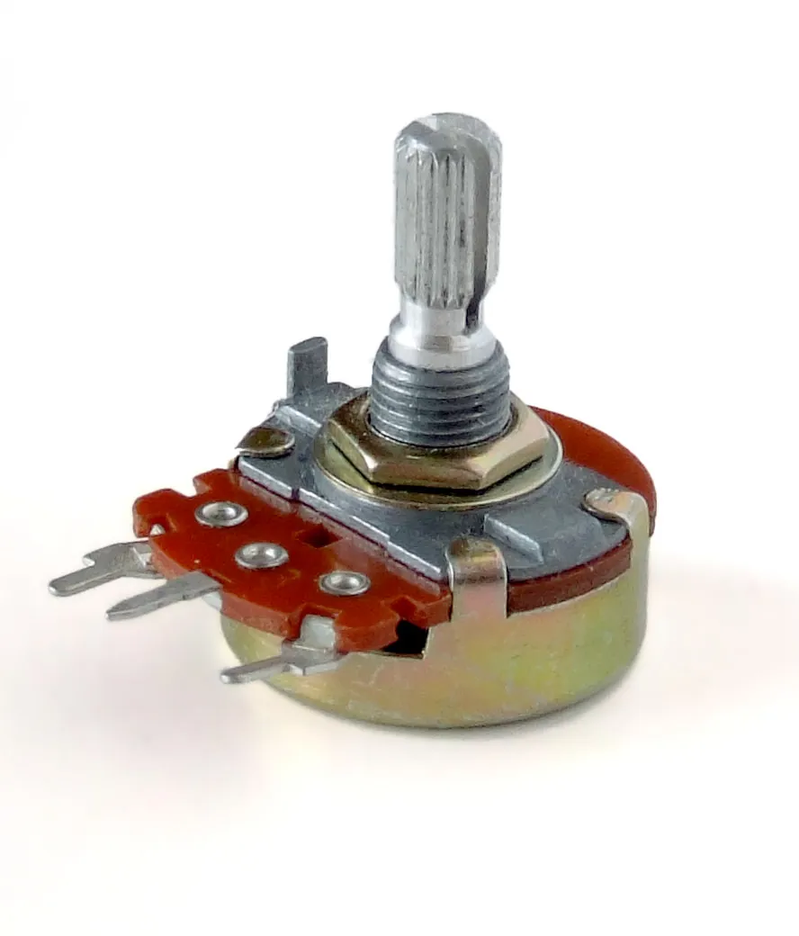
The Arduino reference says analogRead() on an UNO maps 0 V to the operating voltage (5 V) onto whole numbers from 0 to 1023 — a 10-bit result. That number is not an angle yet. If your pot turns through, say, 270° from end to end, each count is 270 ÷ 1023 ≈ 0.264°. That is your resolution: the smallest change you can see. Always convert to real units (degrees, mm, m/s) *before* computing the error, and calibrate against a protractor because no pot is perfectly linear.
angle (°) = counts × (pot travel in °) ÷ 1023
- Check your pot’s datasheet for its travel and measure the real end points — then correct the formula.
Noise: the shaky-scale problem
Real readings jitter by a few counts — electrical noise, a slightly loose wire, vibration. If the controller reacts to every flicker, the motor twitches. Two simple tools:
- Averaging: read 8 or 16 times and take the mean. Noise cancels out; the true value stays. (Too much averaging makes the reading *late* — Lesson 12 covers that trade-off.)
- Dead band: if the error is tiny (say under 1°), treat it as zero and hold. The joint stops chasing noise. The cost: it can rest anywhere inside the band.
The wrap-around trap
A compass says 350°; you want 10°. Naively, error = 10 − 350 = −340°, so the robot turns 340° the long way round. The truth is “20° to the right”. For anything that wraps around (headings, continuous joints), wrap the error into the range −180° to +180° first. The code lab has a three-line wrap180() function that does it.
Visual
Visualise it: watch the error
Change the setpoint and watch the **error** — the gap between what you want and what the sensor says. Positive error means the output is below the setpoint; the controller works to shrink it.
Interactive · Control loop explorer

Mode
Closed
θ final
61.6°
Error
-1.6°
Closed-loop uses error = setpoint − feedback. Open-loop ignores feedback — load disturbances leave steady-state error.
Code lab
Code lab: from raw counts to a trustworthy error
The script converts 10-bit readings to degrees, shows the resolution, computes the error from noisy readings, averages them, applies a dead band and fixes heading wrap-around. Run it with python3 setpoint_error.py.
# setpoint_error.py - turning a raw sensor reading into a trustworthy error.
# 1) A 10-bit ADC reads a potentiometer joint sensor (0..1023 counts over 0..270 deg).
# 2) We convert counts -> degrees, compute error = setpoint - measured, and see the
#    resolution limit, the effect of noise, a dead band, and the "wrap-around" trap for headings.
import random
random.seed(7)

POT_RANGE_DEG = 270.0       # example travel; check YOUR pot's datasheet
ADC_MAX = 1023              # 10-bit ADC on an Arduino UNO: 0..1023

def counts_to_deg(c):
    return c * POT_RANGE_DEG / ADC_MAX

def deg_to_counts(d):
    return round(d * ADC_MAX / POT_RANGE_DEG)

print("1) Resolution: one ADC count =", f"{POT_RANGE_DEG/ADC_MAX:.3f} deg", "\n")

setpoint = 90.0
print("2) Error with a noisy sensor (true angle 88.0 deg, noise +/-2 counts)")
true = 88.0
for i in range(5):
    c = deg_to_counts(true) + random.randint(-2, 2)
    m = counts_to_deg(c)
    print(f"   reading {i+1}: counts={c:4d}  measured={m:6.2f} deg  error={setpoint-m:+6.2f} deg")
avg = sum(counts_to_deg(deg_to_counts(true) + random.randint(-2, 2)) for _ in range(16)) / 16
print(f"   average of 16 readings: {avg:.2f} deg -> error {setpoint-avg:+.2f} deg\n")

print("3) Dead band: ignore errors smaller than 0.75 deg so the motor stops buzzing")
for e in (3.2, 0.9, 0.6, -0.4, -1.8):
    print(f"   error {e:+.1f} deg -> {'act' if abs(e) > 0.75 else 'hold (inside dead band)'}")
print()

def wrap180(e):
    """Shortest signed angle difference in (-180, 180]."""
    e = (e + 180.0) % 360.0 - 180.0
    return 180.0 if e == -180.0 else e

print("4) Heading wrap-around (a mobile robot's compass heading)")
for sp, meas in ((10, 350), (350, 10), (180, 0), (90, 45)):
    naive = sp - meas
    print(f"   setpoint {sp:3d}, measured {meas:3d}: naive error {naive:+5d}  ->  wrapped error {wrap180(naive):+6.1f}")
print("\nSign rule used everywhere in this stage: error = setpoint - measured.")
print("Positive error -> 'not there yet, keep going in the + direction'.")
Output (run with python3 setpoint_error.py)
1) Resolution: one ADC count = 0.264 deg

2) Error with a noisy sensor (true angle 88.0 deg, noise +/-2 counts)
   reading 1: counts= 333  measured= 87.89 deg  error= +2.11 deg
   reading 2: counts= 332  measured= 87.62 deg  error= +2.38 deg
   reading 3: counts= 334  measured= 88.15 deg  error= +1.85 deg
   reading 4: counts= 331  measured= 87.36 deg  error= +2.64 deg
   reading 5: counts= 331  measured= 87.36 deg  error= +2.64 deg
   average of 16 readings: 87.84 deg -> error +2.16 deg

3) Dead band: ignore errors smaller than 0.75 deg so the motor stops buzzing
   error +3.2 deg -> act
   error +0.9 deg -> act
   error +0.6 deg -> hold (inside dead band)
   error -0.4 deg -> hold (inside dead band)
   error -1.8 deg -> act

4) Heading wrap-around (a mobile robot's compass heading)
   setpoint  10, measured 350: naive error  -340  ->  wrapped error  +20.0
   setpoint 350, measured  10: naive error  +340  ->  wrapped error  -20.0
   setpoint 180, measured   0: naive error  +180  ->  wrapped error +180.0
   setpoint  90, measured  45: naive error   +45  ->  wrapped error  +45.0

Sign rule used everywhere in this stage: error = setpoint - measured.
Positive error -> 'not there yet, keep going in the + direction'.
Try it: drag the A0 slider — that is your potentiometer turning a voltage into a 10-bit number. Convert a few readings to degrees in your notebook.
Interactive · GPIO / ADC / PWM Lab
Fake MCU board for digital out, analog in, and PWM duty. Browser-only — never talks to real USB/serial/hardware.
GPIO D7
Good for LEDs / logic — not motors.
ADC A0 (10-bit)
raw 512 → 2.50 V
Pot / distance proxy → robot perception.
PWM D9
duty 40%
PWM → driver → motor — never GPIO-direct.
board@sim ~ pins: D7=0 A0=512 D9=40% · educational MCU only
Real world
Sensors that close real loops
- Hobby servos: an internal potentiometer measures the shaft (SparkFun).
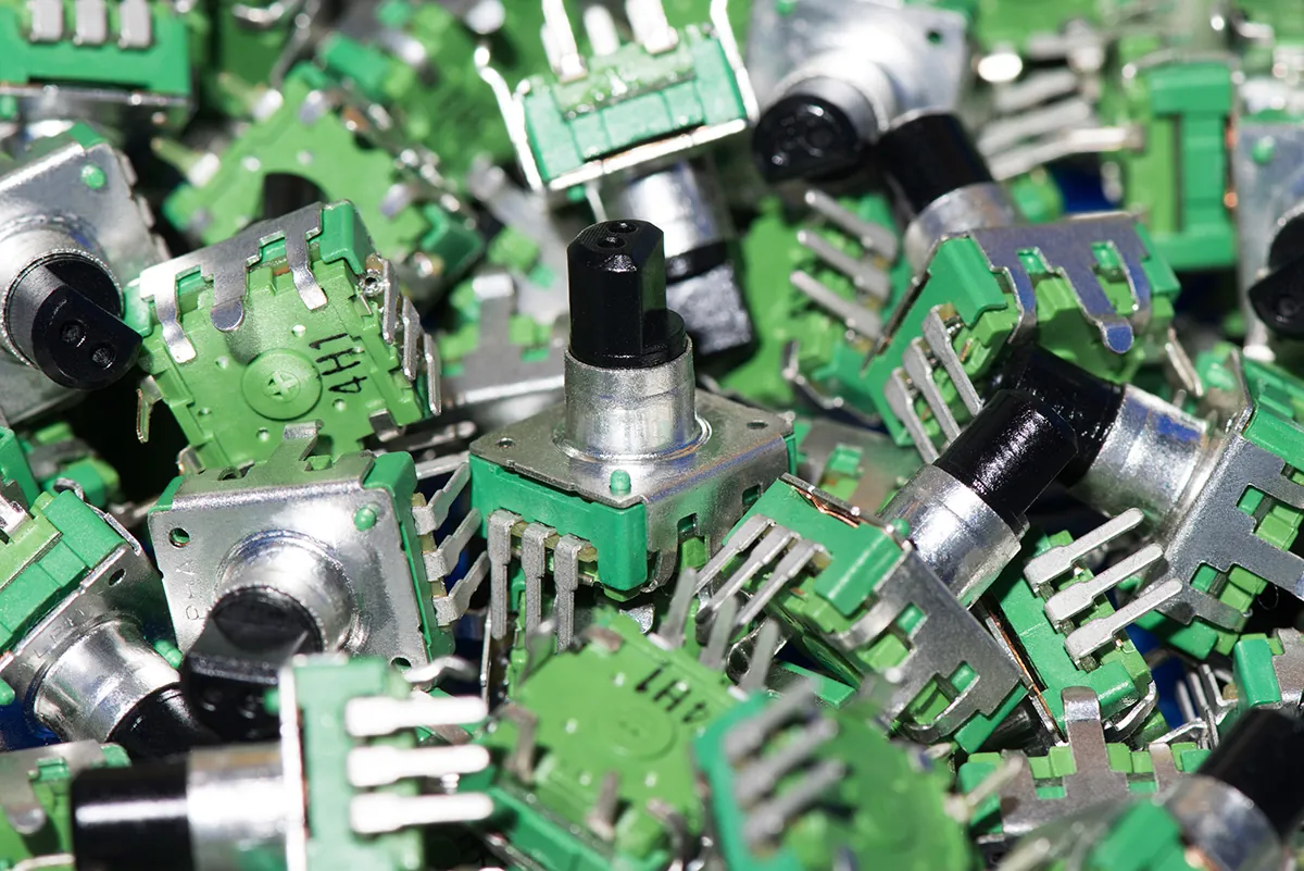
- Robot joints and wheels: encoders count pulses for position and speed.
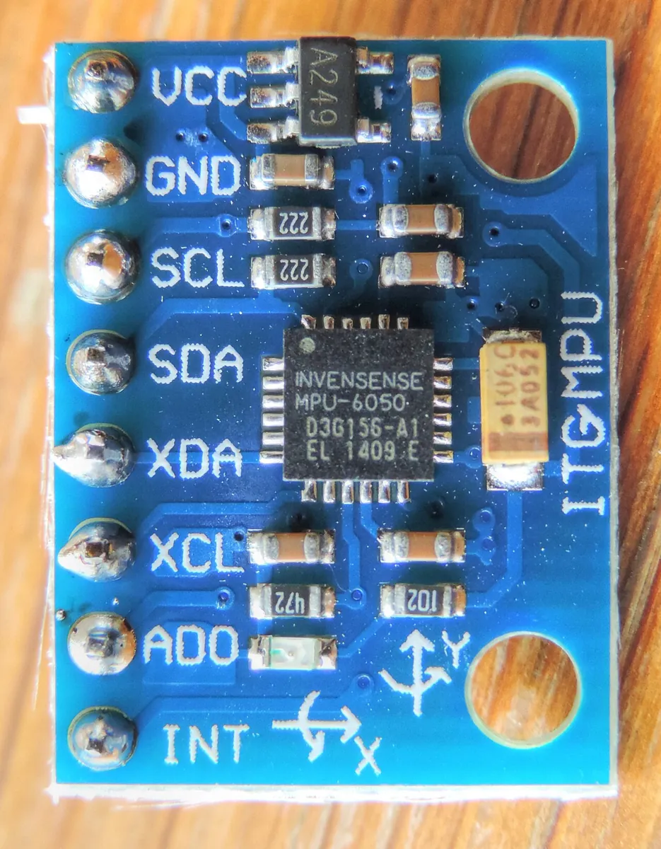
- Balancing robots and drones: gyros measure rotation rate; accelerometers sense the direction of gravity (SparkFun guides).
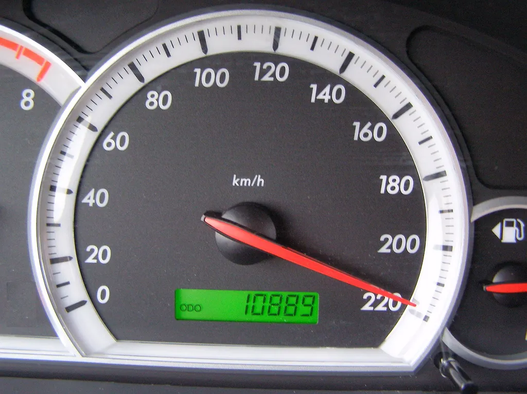
- Cars: cruise control works from a measured vehicle speed — the same quantity your speedometer shows you.
- Shops: digital scales show noisy readings and the shopkeeper uses a mental dead band.
Bench build
Bench build: a live error display
A potentiometer is your joint sensor. Type a setpoint in the Serial Monitor; the Arduino averages eight readings, converts them to degrees and prints the measured angle, the error and whether it is inside the dead band. Turn the knob and watch the error go to zero.
Wire the pot
Outer legs to 5 V and GND; middle leg (wiper) to A0.
Upload and open the monitor
Upload
sensor_error.ino; Serial Monitor at 115200 baud, line ending “Newline”.Give a setpoint
Type
90and press Enter. Turn the knob until the error is inside ±1° and the line says “hold”.Check the sign
Turn the knob *below* the setpoint: the error must be positive. Above it: negative. If not, swap the pot’s outer legs.
Calibrate
Tape a paper protractor under the knob. At 0°, 90° and 180°, note the reading and correct
POT_RANGE_DEGso the printed angle matches.
// sensor_error.ino - read a joint sensor, convert to degrees, compute a clean error.
// A potentiometer on A0 is the joint sensor (outer legs to 5 V and GND, wiper to A0).
// Type a setpoint in degrees in the Serial Monitor (e.g. 90 then Enter).
// The sketch averages 8 readings, prints measured angle, error and whether it is in the dead band.
const int SENSOR_PIN = A0;
const float POT_RANGE_DEG = 270.0;  // check your pot's datasheet and calibrate
const float DEAD_BAND = 1.0;        // degrees
float setpoint = 90.0;

float readAngle() {
  long sum = 0;
  for (int i = 0; i < 8; i++) sum += analogRead(SENSOR_PIN);   // average out noise
  return (sum / 8.0) * POT_RANGE_DEG / 1023.0;
}

void setup() {
  Serial.begin(115200);
  Serial.println(F("Type a setpoint in degrees and press Enter"));
}

void loop() {
  if (Serial.available()) {
    float s = Serial.parseFloat();
    if (s >= 0 && s <= POT_RANGE_DEG) setpoint = s;
    while (Serial.available()) Serial.read();
  }
  float measured = readAngle();
  float error = setpoint - measured;         // the sign rule: setpoint - measured
  Serial.print(F("setpoint=")); Serial.print(setpoint, 1);
  Serial.print(F(" measured=")); Serial.print(measured, 1);
  Serial.print(F(" error="));   Serial.print(error, 1);
  Serial.println(fabs(error) <= DEAD_BAND ? F("  [in dead band: hold]") : F("  [act]"));
  delay(200);
}Debugging
Debugging the error signal
| Symptom | Likely cause | Fix |
|---|---|---|
| Error has the wrong sign | Pot wired the other way, or error computed as measured − setpoint | Swap the pot’s outer legs, or fix the formula to setpoint − measured |
| Reading jumps by 5–10 counts | Noise, loose breadboard contact, long wires | Average 8–16 readings; firm connections; short wires |
| Printed angle wrong at the ends | Pot travel not 270°, or not linear | Calibrate with a protractor at three points |
| Robot turns the long way round | No wrap-around on heading error | Use wrap180() before the controller |
| Joint buzzes at the target | Controller chasing tiny errors | Add a small dead band |
| Joint stops a bit off target | Dead band too wide | Make it narrower, or improve the sensor |
Think
Think about it
Think
Arjun’s turntable robot must face a heading of 5°. Its compass says 358°. His code does `error = 5 - 358` and the robot spins almost a full circle every time. Meanwhile Meera’s arm joint buzzes and gets warm while “holding” at 90°. Diagnose both problems and give each a one-line fix.
Experiment
Try it in the lab: build an error journal
About 30 minutes with the explorer, the script and a potentiometer.
Experiment
Build an error journal
You will need
- Control loop explorer (in your browser)
- Notebook
- Optional: `setpoint_error.py`; Arduino UNO, 10 kΩ potentiometer, paper protractor
Steps
- In the explorer, set three different setpoints and write the error at the start of each move. Check the sign each time.
- Run `setpoint_error.py`. Copy the five noisy errors and the averaged error.
- Change the noise to ±10 counts and find how many readings you need to average to get within 0.5° of the true error.
- Work out the wrapped error by hand for (setpoint 20°, measured 340°) and (setpoint 300°, measured 30°). Check with the script.
- Optional bench: run `sensor_error.ino`, calibrate at 0°, 90° and 180°, and note how many counts the reading jumps when you don’t touch the knob.
Interactive · Control loop explorer
Mode
Closed
θ final
61.6°
Error
-1.6°
Closed-loop uses error = setpoint − feedback. Open-loop ignores feedback — load disturbances leave steady-state error.
A clean error needs the right units, a known resolution, a little averaging, a sensible dead band and a fixed sign rule. With those, every controller you build next has something solid to work with.
Knowledge check
Check your understanding
Knowledge check
1. Error is usually defined as…
2. Bad sensor data causes…
3. An Arduino UNO’s `analogRead()` returns values from…
4. A pot travels 270° over 0–1023 counts. Its resolution is about…
5. Averaging 16 readings mainly helps by…
6. A dead band of ±1° means…
7. Setpoint 10°, compass 350°. The correct heading error is…
8. `error = 90 - analogRead(A0)` is wrong because…
9. A MEMS gyroscope measures…
10. To check the sign of your error on the bench you should…
Mini assignment
Hands-on assignment
Mini assignment
Sensor checklist and error journal
Make one real sensor trustworthy: units, resolution, noise, sign, dead band — and prove it with numbers.
Deliverables
- A sensor checklist for your potentiometer (or the simulated one): units, range, resolution, measured noise in counts and degrees.
- A calibration table with readings at 0°, 90° and 180°, and your corrected conversion formula.
- Output from `setpoint_error.py` with noise changed to ±10 counts, and the number of readings you need to average for 0.5° accuracy.
- Hand-worked wrap-around errors for three heading pairs of your choice, checked with `wrap180()`.
- One paragraph: what dead band would you choose for the 6DOF arm’s gripper joint, and why?
Do this, step by step
- Wire the potentiometer to A0 and flash
sensor_error.ino; note the raw count at both ends of travel and the middle. - Measure the pot at 0°, 90° and 180° with a protractor, write the raw counts, and correct the conversion (
POT_RANGE_DEG= 270.0,ADC_MAX= 1023). - Hold the knob still for 10 seconds and write the noise in counts and in degrees (1 count ≈ 270 ÷ 1023 ≈ 0.26°).
- In
setpoint_error.pychange the noise to ±10 counts, run it, and find how many readings you must average for 0.5° accuracy. - Work out three wrap-around heading errors by hand (e.g. target 170°, measured −170°), check each with
wrap180(), then choose a gripper dead band and justify it in one paragraph.
Stuck? Hints, one at a time
- Hint 1: Resolution = travel ÷ 1023 for a 10-bit reading.
- Hint 2: Measure noise by not touching the knob and watching the highest and lowest reading for 10 s.
- Hint 3: For wrap-around: add 180, take modulo 360, subtract 180.
- Hint 4: A sensible dead band is a little bigger than the noise but much smaller than the accuracy you need.
Challenges (pick by level)
- 🟢 Easy: A 12-bit ADC gives 0–4095. What is the resolution for the same 270° pot?
- 🟢 Easy: Name the setpoint, sensor and error for an AC thermostat.
- 🟡 Medium: Add a moving average (last 8 readings) to
sensor_error.inoinstead of 8 back-to-back reads. Compare the jitter. - 🟡 Medium: Add hysteresis to the dead band: start acting at 1.5°, stop at 0.5°. Why does this help?
- 🟠 Hard-ish: Modify
setpoint_error.pyto measure how much delay a 16-sample moving average adds when the angle ramps at 30 °/s. - 🔴 Hard: Read an encoder with interrupts and print the error in degrees. Compare its resolution with the pot.
- ⚫ Research: Read SparkFun’s *Gyroscope* and *Accelerometer Basics* guides and explain why balancing robots combine both sensors to measure tilt.
Next step
In Lesson 4 — Control Loop Anatomy you put every block on the table — reference, comparator, controller, actuator, plant, sensor, disturbance — and see why the loop rate matters as much as the gain.
Look back: Lesson 2: Open Loop vs Closed Loop. Next: Lesson 4: Control Loop Anatomy. Related: Stage 4 L08: Analog Signals & ADC, Stage 5 L06: Sensors & Proprioception and Stage 1 — Math for Robotics.
Sources
- Modern Robotics — K. M. Lynch & F. C. Park (preprint PDF) — Sec. 11.2: joint error θe(t) = θd(t) − θ(t); the controller aims to drive the error to zero or a small value.
- Control Tutorials (University of Michigan) — Introduction: PID Controller Design — the tracking error is the difference between the desired output and the actual output, and is fed to the controller.
- Arduino reference: analogRead() — maps 0 V to the operating voltage (5 V or 3.3 V) into integers 0–1023 on an UNO.
- SparkFun Learn: Hobby Servo Tutorial — a potentiometer on the output shaft senses servo position.
- SparkFun Learn: Gyroscope — MEMS gyros are small, inexpensive sensors that measure angular velocity, in degrees per second.
- SparkFun Learn: Accelerometer Basics — accelerometers measure acceleration, including the pull of gravity.
- Photos: Wikimedia Commons (credits under each image).
Self-attested for now — keep artifacts in your lab notebook.
Complete
Today's goal
0 of 1 done today
Mark this lesson complete when you have worked the experiment, knowledge check, and assignment (even roughly).