
Electronics & Embedded Systems · Lesson 08
Analog Signals & ADC
Est. 45–60 min
Why
Why your robot needs to measure “how much”, not just “yes or no”
In Lesson 7 a pin answered only yes or no. But robots constantly ask how much: How far is the knob turned? How bright is the room? How tilted is the base? How full is the battery? These are analog quantities — they can take any value in a range. A sensor turns them into a voltage, and the microcontroller’s ADC (analog-to-digital converter) turns that voltage into a number your code can use.
By the end you will be able to: explain resolution and step size (LSB), convert ADC counts to volts and back using the datasheet formula, choose a reference voltage, wire a potentiometer and a light sensor as voltage dividers, scale a battery voltage safely into an analog pin, map a reading to a servo angle, and clean noisy readings with averaging, smoothing and hysteresis — without ever putting more than the board’s supply voltage on a pin.
Concept
Analog signals and the ADC in plain words
Think of filling a bucket from a tap and measuring it with a measuring jug marked in steps. The water level can be anything, but you can only write down the nearest mark. A finer jug (more marks) gives a better answer. An ADC is that jug: the voltage can be anything between 0 and the reference voltage, and the ADC reports the nearest step as a whole number.
Resolution: how many steps
An ADC with n bits has 2ⁿ steps. The Uno R3’s ATmega328P has a 10-bit ADC: 2¹⁰ = 1024 steps, reported as 0 to 1023 (Arduino’s analogRead() reference). SparkFun notes that some microcontrollers have 8-bit ADCs (256 levels) and some 16-bit (65 536 levels). The Raspberry Pi Pico has a 12-bit ADC (4096 levels), and the Arduino UNO R4 can go up to 14 bits — but Arduino keeps the default at 10 bits for compatibility until you call analogReadResolution().
1 LSB = Vref ÷ 2ⁿ
- LSB = least significant bit = the size of one step
- Uno R3, Vref 5 V, 10 bits → 5 ÷ 1024 ≈ 4.9 mV per step (Arduino’s analogRead() reference)
- Same chip with the INTERNAL 1.1 V reference → about 1.07 mV per step — finer, but only up to 1.1 V
From volts to counts, and back
The ATmega328P datasheet gives the conversion result as ADC = VIN × 1024 ÷ VREF, where 0 means ground and 1023 means “VREF minus one step” (or more). So 2.5 V on a 5 V reference reads 512, and SparkFun’s worked example of 2.12 V reads 434. Going back, volts = counts × VREF ÷ 1024. Many tutorials — including SparkFun’s and this course’s Lesson 5 sketch — divide by 1023 instead, so that a full-scale 1023 prints exactly 5.00 V. The two differ by less than one step; pick one, write it in a comment, and be consistent.
counts = Vin × 1024 ÷ Vref Vin ≈ counts × Vref ÷ 1024
- Vin = voltage at the analog pin, Vref = reference voltage (5 V by DEFAULT on an Uno)
- Example: 3.3 V system, reading 512 → about 1.65 V (SparkFun)
- Result is clamped: an Uno cannot report more than 1023, whatever the voltage
| Board | Resolution | Default range | Speed | Source |
|---|---|---|---|---|
| Arduino Uno R3 (ATmega328P) | 10-bit (0–1023) | 0–5 V (DEFAULT reference) | About 100 µs per analogRead(), roughly 10 000 reads/s | Arduino analogRead() reference |
| Arduino UNO R4 Minima / WiFi | Up to 14-bit; default 10-bit | 0–5 V | — | Arduino analogRead() reference |
| Raspberry Pi Pico (RP2040) | 12-bit, 500 ksps | 0–3.3 V (filtered 3.3 V as ADC_VREF) | Up to 500 000 samples/s | Raspberry Pi Pico datasheet |
Choosing the reference
Arduino’s analogReference() reference lists the options for the Uno: DEFAULT (the board’s 5 V), INTERNAL (1.1 V on the ATmega328P) and EXTERNAL (whatever you put on the AREF pin, 0–5 V only). Because the default reference is the 5 V supply itself, a reading is ratiometric: if the supply sags, the reference sags with it. For a potentiometer powered from the same 5 V, that is perfect — the knob’s position reads the same. For measuring an absolute voltage like a battery, it means your 5 V must be known (measure it), or you use the internal reference with a bigger divider. Two warnings from the same page: never put less than 0 V or more than 5 V on AREF, and set EXTERNAL before calling analogRead(), otherwise you short the internal reference to AREF.
Inside the ATmega328P’s ADC (just enough)
The datasheet describes a successive approximation ADC with a sample-and-hold circuit: it grabs the voltage, holds it steady, then compares it against reference fractions bit by bit, like guessing a number with “higher or lower”. A conversion takes 13–260 µs, the absolute accuracy is ±2 LSB, and the ADC is optimised for signal sources with an output impedance of about 10 kΩ or less. It also advises removing frequencies above half your sampling rate with a low-pass filter before the ADC. Six channels (A0–A5 on the Uno) share this one ADC through a selector.
How it works
How it actually works: sensors as voltage dividers
The potentiometer: a divider you can turn
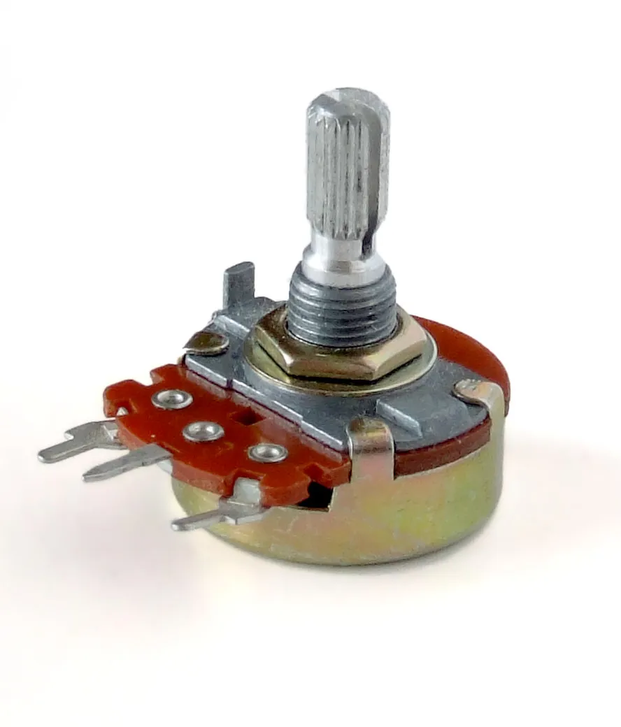
SparkFun’s voltage-divider tutorial calls a potentiometer a variable resistor used as an adjustable voltage divider: pins 1 and 3 are the ends of the track, pin 2 is the wiper. Put 5 V and GND on the ends and the wiper gives 0–5 V. Because the reading depends on the ratio of the two halves, a pot on the Uno’s own 5 V is ratiometric — a small sag in 5 V doesn’t move the reading.
Resistive sensors: add one fixed resistor
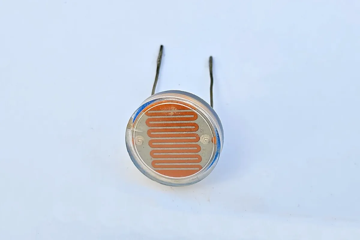
Many sensors are simply resistors that change: SparkFun lists photocells, flex sensors, force-sensitive resistors and thermistors. A microcontroller can’t read resistance directly, but it can read voltage. So you pair the sensor with a fixed resistor to make a divider. Adafruit’s photocell guide connects the photocell from power to the analog pin, and a 10 kΩ pull-down from the pin to ground: more light → lower photocell resistance → higher voltage at the pin.
| Light | Photocell resistance | Voltage at the pin | About how many counts (×1024/5) |
|---|---|---|---|
| Dim hallway (0.1 lux) | 600 kΩ | 0.1 V | 20 |
| Moonlit night (1 lux) | 70 kΩ | 0.6 V | 123 |
| Dark room (10 lux) | 10 kΩ | 2.5 V | 512 |
| Bright room (100 lux) | 1.5 kΩ | 4.3 V | 880 |
| Overcast day (1000 lux) | 300 Ω | ≈ 5 V | ≈ 1023 (saturated) |
Sensors that already give a voltage
Some sensors have their own electronics and output a voltage directly — no divider needed. You only need to make sure the sensor’s supply and output range fit your board’s ADC range.
Higher voltages: scale them down first
To watch a robot battery that is higher than 5 V, use a divider to bring it below the reference. Two equal 10 kΩ resistors halve the voltage: a 2-cell Li-ion pack at a full 8.4 V becomes 4.2 V at the pin. The divider’s source impedance is the two resistors in parallel, 5 kΩ — inside the datasheet’s 10 kΩ recommendation. The cost: the divider always draws a small current (0.42 mA at 8.4 V) from the battery.
Know the maximum
Write the highest voltage the source can ever reach (a full battery, a charger connected).
Choose the ratio
Pick R1 (top) and R2 (bottom) so Vmax × R2 ÷ (R1 + R2) stays below Vref with some margin.
Keep it ≤ 10 kΩ
R1 ∥ R2 should be about 10 kΩ or less so the ADC reads accurately.
Measure before connecting
With the divider built and the board unplugged, check the middle point with a meter at the highest source voltage.
Common ground
Battery − to board GND, or the reading means nothing.
Clean signals
Noise: why readings wobble and how to clean them
A reading that jumps by a few counts is normal: the ADC itself is accurate to about ±2 LSB, the supply has ripple, and wires pick up noise from motors. Arduino’s analogRead() reference adds that an unconnected analog pin gives values that wander with things like a hand moving nearby. Arduino’s analog-input guide also warns that switching other analog pins as digital outputs right before a reading can add noise and jitter, and that turning on a pull-up on an analog pin changes its readings.
| Technique | What it does | Cost |
|---|---|---|
| Average N readings | Random noise shrinks by about √N (16 readings → about 4× quieter) | N times slower (16 × 100 µs = 1.6 ms on an Uno) |
| Exponential smoothing | new = old + α × (raw − old): one variable, very light | Lags behind fast changes; smaller α = smoother but slower |
| Hysteresis | Two thresholds (ON above one, OFF below another) stop on/off chatter | A dead band where nothing changes |
| Hardware RC filter | A resistor and capacitor before the pin remove fast noise | Slows the signal; keep the resistor ≲ 10 kΩ |
| Good wiring | Short wires, sensor ground next to its signal, away from motor wires | Planning time — the cheapest fix of all |
Visual
Visualise it: from a knob’s voltage to a number
Drag the **A0** slider from 0 to 1023 and watch the voltage follow. The lab converts with raw ÷ 1023 × 5 V — the popular convention; the datasheet’s ÷ 1024 gives values within one step of it. The note “Pot / distance proxy → robot perception” is the key idea: the robot turns a voltage into a number, then into a decision. The D7 GPIO toggle is from Lesson 7, and D9 PWM is next. Browser simulation only — no real pins are touched.
Interactive · GPIO / ADC / PWM Lab
Fake MCU board for digital out, analog in, and PWM duty. Browser-only — never talks to real USB/serial/hardware.
GPIO D7
Good for LEDs / logic — not motors.
ADC A0 (10-bit)
raw 512 → 2.50 V
Pot / distance proxy → robot perception.
PWM D9
duty 40%
PWM → driver → motor — never GPIO-direct.
board@sim ~ pins: D7=0 A0=512 D9=40% · educational MCU only
Code lab
Code lab: counts, volts, dividers and filters in Python
1. The ADC toolkit
This script prints the step size for four common setups, converts volts to counts with the datasheet formula, compares the /1024 and /1023 conventions, designs a battery divider and checks its source impedance, and maps a pot reading to a servo angle like Arduino’s map().
# adc_toolkit.py — turn ADC counts into volts, and volts into counts, the honest way.
# Stage 4, Lesson 8. Simulation only: arithmetic and prints. No pins, no hardware.

def lsb(vref, bits):
    return vref / (2 ** bits)


print("1) Step size (1 LSB) for common setups")
print("-" * 70)
for name, vref, bits in (("Uno R3, DEFAULT 5 V", 5.0, 10),
                         ("Uno R3, INTERNAL 1.1 V", 1.1, 10),
                         ("Pico, 3.3 V reference", 3.3, 12),
                         ("Uno R4, 14-bit mode", 5.0, 14)):
    print(f"  {name:<24} {bits:2d} bits -> {2**bits:5d} codes, 1 LSB = {lsb(vref, bits)*1000:6.3f} mV")

print()
print("2) Datasheet formula ADC = Vin x 1024 / Vref (ATmega328P, 10-bit, Vref 5 V)")
print("-" * 70)
for vin in (0.0, 1.0, 2.12, 2.5, 4.99, 5.0):
    code = min(1023, int(vin * 1024 / 5.0))
    print(f"  Vin {vin:4.2f} V -> code {code:4d}")
print("  Code 1023 means 'Vref minus 1 LSB or more' — the ADC can't count past 1023.")

print()
print("3) Counts back to volts: /1024 vs the popular /1023")
print("-" * 70)
for code in (0, 1, 434, 512, 1023):
    print(f"  code {code:4d} -> {code * 5.0 / 1024:6.4f} V (/1024)   {code * 5.0 / 1023:6.4f} V (/1023)")
print("  The two differ by less than 1 LSB (4.9 mV). Pick one, write it down, be consistent.")

print()
print("4) Battery monitor: divide 2S Li-ion (max 8.4 V) below 5 V before A1")
print("-" * 70)
R_TOP, R_BOT = 10_000, 10_000
ratio = R_BOT / (R_TOP + R_BOT)
for vbat in (8.4, 7.4, 6.6, 6.0):
    v_pin = vbat * ratio
    code = int(v_pin * 1024 / 5.0)
    back = code * 5.0 / 1024 / ratio
    print(f"  battery {vbat:3.1f} V -> pin {v_pin:4.2f} V -> code {code:4d} -> firmware says {back:4.2f} V")
print(f"  Divider current = 8.4 V / {(R_TOP + R_BOT)//1000} k = {8.4/(R_TOP+R_BOT)*1000:.2f} mA (always flowing!)")
print(f"  Source impedance seen by ADC = R_top || R_bot = {R_TOP*R_BOT/(R_TOP+R_BOT)/1000:.1f} k (<= 10 k: good)")

print()
print("5) Map a pot reading to a servo angle, like Arduino map()")
print("-" * 70)
for raw in (0, 256, 512, 768, 1023):
    angle = raw * 180 // 1023          # integer maths, same as map(raw, 0, 1023, 0, 180)
    print(f"  raw {raw:4d} -> {angle:3d} deg")
Output (run with python3 adc_toolkit.py)
1) Step size (1 LSB) for common setups
----------------------------------------------------------------------
  Uno R3, DEFAULT 5 V      10 bits ->  1024 codes, 1 LSB =  4.883 mV
  Uno R3, INTERNAL 1.1 V   10 bits ->  1024 codes, 1 LSB =  1.074 mV
  Pico, 3.3 V reference    12 bits ->  4096 codes, 1 LSB =  0.806 mV
  Uno R4, 14-bit mode      14 bits -> 16384 codes, 1 LSB =  0.305 mV

2) Datasheet formula ADC = Vin x 1024 / Vref (ATmega328P, 10-bit, Vref 5 V)
----------------------------------------------------------------------
  Vin 0.00 V -> code    0
  Vin 1.00 V -> code  204
  Vin 2.12 V -> code  434
  Vin 2.50 V -> code  512
  Vin 4.99 V -> code 1021
  Vin 5.00 V -> code 1023
  Code 1023 means 'Vref minus 1 LSB or more' — the ADC can't count past 1023.

3) Counts back to volts: /1024 vs the popular /1023
----------------------------------------------------------------------
  code    0 -> 0.0000 V (/1024)   0.0000 V (/1023)
  code    1 -> 0.0049 V (/1024)   0.0049 V (/1023)
  code  434 -> 2.1191 V (/1024)   2.1212 V (/1023)
  code  512 -> 2.5000 V (/1024)   2.5024 V (/1023)
  code 1023 -> 4.9951 V (/1024)   5.0000 V (/1023)
  The two differ by less than 1 LSB (4.9 mV). Pick one, write it down, be consistent.

4) Battery monitor: divide 2S Li-ion (max 8.4 V) below 5 V before A1
----------------------------------------------------------------------
  battery 8.4 V -> pin 4.20 V -> code  860 -> firmware says 8.40 V
  battery 7.4 V -> pin 3.70 V -> code  757 -> firmware says 7.39 V
  battery 6.6 V -> pin 3.30 V -> code  675 -> firmware says 6.59 V
  battery 6.0 V -> pin 3.00 V -> code  614 -> firmware says 6.00 V
  Divider current = 8.4 V / 20 k = 0.42 mA (always flowing!)
  Source impedance seen by ADC = R_top || R_bot = 5.0 k (<= 10 k: good)

5) Map a pot reading to a servo angle, like Arduino map()
----------------------------------------------------------------------
  raw    0 ->   0 deg
  raw  256 ->  45 deg
  raw  512 ->  90 deg
  raw  768 -> 135 deg
  raw 1023 -> 180 deg
2. Cleaning a noisy sensor
This script makes fake noisy readings (with a fixed random seed, so the output repeats exactly) and compares single reads with averages of 16, shows exponential smoothing following a sudden jump, and counts how often a light-sensor switch would click with one threshold versus with hysteresis.
# sensor_filter.py — clean up a noisy analog sensor: averaging, smoothing, and a threshold with hysteresis.
# Stage 4, Lesson 8. Simulation only: fake readings from a seeded random generator. No hardware.
import random
import statistics

random.seed(8)                       # fixed seed, so this output repeats exactly
TRUE_RAW = 512                       # what a perfect ADC would read (2.5 V on a 5 V, 10-bit ADC)


def noisy():
    return max(0, min(1023, round(random.gauss(TRUE_RAW, 6))))   # +/- about 6 counts of noise


print("1) Single readings vs averages of 16")
print("-" * 64)
singles = [noisy() for _ in range(200)]
averages = [sum(noisy() for _ in range(16)) / 16 for _ in range(200)]
print(f"  single reads : spread (std dev) = {statistics.pstdev(singles):4.2f} counts, "
      f"range {min(singles)}..{max(singles)}")
print(f"  avg of 16    : spread (std dev) = {statistics.pstdev(averages):4.2f} counts, "
      f"range {min(averages):.1f}..{max(averages):.1f}")
print("  Averaging N readings cuts random noise by about sqrt(N): sqrt(16) = 4.")

print()
print("2) Exponential smoothing (one line of code, very little memory), alpha = 0.2")
print("-" * 64)
smooth = None
for step in range(12):
    target = 300 if step < 6 else 700           # the real signal jumps at step 6
    raw = max(0, min(1023, round(random.gauss(target, 6))))
    smooth = raw if smooth is None else smooth + 0.2 * (raw - smooth)
    print(f"  step {step:2d}: raw {raw:4d}  smoothed {smooth:6.1f}")
print("  Smoother = slower. Bigger alpha follows faster but lets more noise through.")

print()
print("3) Light-sensor threshold: one threshold chatters, hysteresis doesn't")
print("-" * 64)
light = [498, 503, 497, 505, 499, 502, 496, 540, 560, 548, 506, 494, 470, 455]
state_single, flips_single = False, 0
state_hyst, flips_hyst = False, 0
for v in light:
    new_single = v > 500
    flips_single += new_single != state_single
    state_single = new_single
    if not state_hyst and v > 530:
        state_hyst, flips_hyst = True, flips_hyst + 1
    elif state_hyst and v < 470:
        state_hyst, flips_hyst = False, flips_hyst + 1
print(f"  readings: {light}")
print(f"  single threshold at 500       -> {flips_single} on/off changes (relay clicking!)")
print(f"  hysteresis ON >530, OFF <470  -> {flips_hyst} changes")
Output (run with python3 sensor_filter.py)
1) Single readings vs averages of 16
----------------------------------------------------------------
  single reads : spread (std dev) = 6.14 counts, range 496..531
  avg of 16    : spread (std dev) = 1.56 counts, range 508.2..516.3
  Averaging N readings cuts random noise by about sqrt(N): sqrt(16) = 4.

2) Exponential smoothing (one line of code, very little memory), alpha = 0.2
----------------------------------------------------------------
  step  0: raw  287  smoothed  287.0
  step  1: raw  300  smoothed  289.6
  step  2: raw  292  smoothed  290.1
  step  3: raw  302  smoothed  292.5
  step  4: raw  290  smoothed  292.0
  step  5: raw  297  smoothed  293.0
  step  6: raw  699  smoothed  374.2
  step  7: raw  702  smoothed  439.7
  step  8: raw  712  smoothed  494.2
  step  9: raw  699  smoothed  535.2
  step 10: raw  705  smoothed  569.1
  step 11: raw  692  smoothed  593.7
  Smoother = slower. Bigger alpha follows faster but lets more noise through.

3) Light-sensor threshold: one threshold chatters, hysteresis doesn't
----------------------------------------------------------------
  readings: [498, 503, 497, 505, 499, 502, 496, 540, 560, 548, 506, 494, 470, 455]
  single threshold at 500       -> 8 on/off changes (relay clicking!)
  hysteresis ON >530, OFF <470  -> 2 changes
Real world
Where ADCs help real robots sense the world
- Teach pendants and joysticks: knobs and analog thumb joysticks (SparkFun lists a 2-axis joystick among its potentiometer examples) give voltages an ADC reads — the same idea as Arjun’s knob box.
- Battery monitors: robots, drones and e-bikes divide the pack voltage down to an ADC pin and warn (with hysteresis) before the battery runs flat.
- Light and line sensors: photocells and phototransistors turn brightness into a voltage, so a robot can follow a line or turn on lights at dusk.
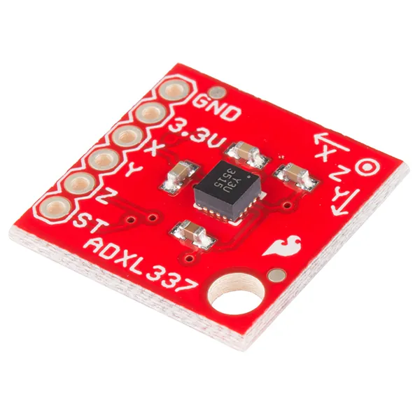
- Tilt and balance: analog accelerometers like the ADXL337 give one voltage per axis for tilt sensing.
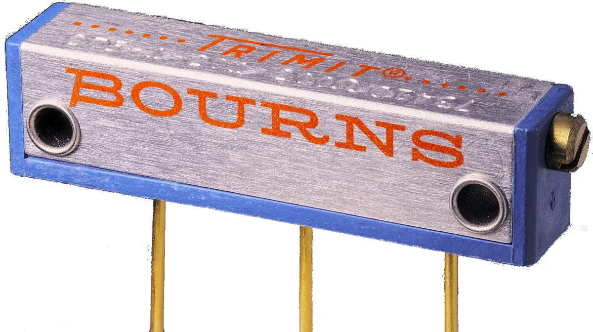
- Calibration and reference voltages: trimmer potentiometers set a reference voltage or a threshold once, so a sensor board reads correctly.
- Temperature: thermistors in a divider let a robot watch its motors or battery for overheating.
Bench build
Bench build: a knob, a battery monitor and a low-battery warning
You need an Uno (or compatible 5 V board), a 10 kΩ potentiometer, two 10 kΩ resistors, a multimeter and — only if you have one and know how to handle it safely — a 2-cell battery pack. Without a battery, feed the divider from the board’s 5V pin to practise; the sketch will simply read about 5 V.
Pot to A0
Outer legs to 5V and GND, wiper (middle) to A0.
Divider to A1
Source + → 10 kΩ → A1 → 10 kΩ → GND. Source − → Arduino GND.
Meter check first
Before connecting A1, measure the divider’s middle point. It must be below 5 V at the source’s highest voltage.
Upload and watch
Open the Serial Monitor at 9600 baud. Turn the knob end to end: raw 0 → 1023, angle 0 → 180.
Calibrate
Measure the Uno’s 5V pin and the real battery voltage with your meter. Edit
VREFuntil the printed battery voltage matches the meter.Test the warning
If you have a bench supply, lower its voltage slowly: the LED turns on below 6.6 V and off only above 6.9 V.
// analog_monitor.ino — read a knob and a battery voltage, smooth them, warn with hysteresis
// (Stage 4, Lesson 8).
// For a REAL board on your bench. This sketch is not run inside the browser.
// Knob:    10 kOhm potentiometer: one end -> 5V, other end -> GND, middle (wiper) -> A0.
// Battery: battery (+) -> 10 kOhm -> A1 -> 10 kOhm -> GND   (halves it: 8.4 V becomes 4.2 V at A1)
//          battery (-) -> Arduino GND (common ground). CHECK with a meter that A1 is below 5 V
//          BEFORE connecting it. NEVER connect a battery straight to an analog pin.
// Warning: example thresholds only — use your battery's datasheet for real limits.

const int KNOB_PIN = A0;
const int BATT_PIN = A1;
const int LED_PIN = 13;
const float VREF = 5.0;          // DEFAULT reference on a 5 V Uno — measure your 5V pin and edit this
const float DIVIDER = 2.0;       // two equal 10 kOhm resistors
const float LOW_ON = 6.6;        // warning turns ON below this (V)
const float LOW_OFF = 6.9;       // and only turns OFF again above this (hysteresis)

bool lowWarning = false;

int readAverage(int pin, int n) {
  long sum = 0;
  for (int i = 0; i < n; i++) sum += analogRead(pin);   // each read takes about 100 us on an Uno
  return sum / n;
}

void setup() {
  pinMode(LED_PIN, OUTPUT);
  Serial.begin(9600);
}

void loop() {
  int knobRaw = readAverage(KNOB_PIN, 16);
  int angle = map(knobRaw, 0, 1023, 0, 180);            // a servo target, printed only

  int battRaw = readAverage(BATT_PIN, 16);
  float battV = battRaw * VREF / 1024.0 * DIVIDER;      // datasheet formula: ADC = Vin x 1024 / Vref

  if (!lowWarning && battV < LOW_ON) lowWarning = true;
  if (lowWarning && battV > LOW_OFF) lowWarning = false;
  digitalWrite(LED_PIN, lowWarning ? HIGH : LOW);

  Serial.print("knob raw "); Serial.print(knobRaw);
  Serial.print(" -> angle "); Serial.print(angle);
  Serial.print(" | battery raw "); Serial.print(battRaw);
  Serial.print(" -> "); Serial.print(battV, 2); Serial.print(" V");
  Serial.println(lowWarning ? "  LOW!" : "");
  delay(200);
}| Check | Meter mode | Power | What you expect |
|---|---|---|---|
| Pot track | Resistance, outer legs | OFF | About 10 kΩ |
| Divider ratio | Resistance, each resistor | OFF | About 10 kΩ each |
| Divider output | DC volts, A1 node to GND | Source ON, board unplugged | About half the source voltage, below 5 V |
| Knob at mid | DC volts, A0 to GND | ON | About 2.5 V, raw about 512 |
| Uno 5V pin | DC volts | ON | Near 5 V — write the exact value into VREF |
Debugging
Debugging: when the numbers don’t make sense
| Symptom | Likely cause | Fix |
|---|---|---|
| Reading wanders even with nothing changing, by hundreds of counts | Floating pin: the wiper or sensor isn’t really connected | Check every jumper; make sure the sensor is wired to the pin you read |
| Always 1023 | Input at or above Vref, or a divider wired backwards | Measure the pin; recheck the divider order (top to source, bottom to GND) |
| Always 0 | Missing supply to the pot/sensor, or no common ground | Check 5V and GND at the sensor, and the shared ground |
| Battery voltage a little wrong | VREF in code isn’t your real 5 V; resistor tolerance | Measure 5V and the battery with a meter; calibrate in code |
| Readings jump when a motor runs | Motor noise on the supply or ground; long wires | Separate motor supply, common ground at one point, average or smooth |
| Readings odd after using analogReference() | First readings after a reference change can be wrong | Throw away a few readings after changing the reference |
| Reading off after enabling INPUT_PULLUP on an analog pin | The pull-up forms a divider with your sensor | Don’t enable the pull-up on analog inputs |
Think
Think about it
Think
Arjun wants better resolution for his battery monitor, so he switches to `analogReference(INTERNAL)` (1.1 V) but keeps his 10 kΩ / 10 kΩ divider on a 2-cell pack. What happens to the readings, and how should he fix the divider?
Experiment
Try it in the lab: read, convert and clean a signal
Twenty minutes with the GPIO / ADC / PWM lab, the two Python scripts and your notebook. You will convert, compare, design a divider and clean a signal — with numbers you can check.
Experiment
From voltage to decision
You will need
- GPIO / ADC / PWM lab (below, runs in your browser)
- Notebook or a text file
- Optional: your laptop to run `adc_toolkit.py` and `sensor_filter.py`
Steps
- In the lab, set the A0 slider to 0, 256, 512, 768 and 1023. Write the voltage the lab shows for each.
- For the same counts, calculate volts with the datasheet’s ÷ 1024 formula. Write the difference for each — is it ever more than one step (4.9 mV)?
- Run `adc_toolkit.py`. Copy the step size for the Uno at 5 V and at 1.1 V. Write one sentence on when you would use each.
- Design a divider for a 3S Li-ion pack (12.6 V full) so the pin stays below 4.5 V and R1 ∥ R2 ≤ 10 kΩ. Check it in the script.
- Run `sensor_filter.py`. Copy the spread (std dev) for single reads and for averages of 16, and the number of on/off changes with and without hysteresis.
- Write your plan for Arjun’s teach pendant: which filter for the knobs, which for the battery warning, and why.
Interactive · GPIO / ADC / PWM Lab
Fake MCU board for digital out, analog in, and PWM duty. Browser-only — never talks to real USB/serial/hardware.
GPIO D7
Good for LEDs / logic — not motors.
ADC A0 (10-bit)
raw 512 → 2.50 V
Pot / distance proxy → robot perception.
PWM D9
duty 40%
PWM → driver → motor — never GPIO-direct.
board@sim ~ pins: D7=0 A0=512 D9=40% · educational MCU only
An ADC turns a voltage into a number in steps. Good design keeps the voltage inside the range, chooses a reference that fits, gives the ADC a low-impedance source, and cleans the result just enough — averaging for steadiness, hysteresis for decisions.
Knowledge check
Check your understanding
Knowledge check
1. How many different values can a 10-bit ADC report?
2. On an Uno R3 with the DEFAULT 5 V reference, about how big is one ADC step?
3. Using the datasheet formula ADC = Vin × 1024 ÷ Vref, what does 2.5 V read with a 5 V reference?
4. A photocell is wired from 5 V to A0 with a 10 kΩ resistor from A0 to GND. The room gets brighter. What happens to the reading?
5. Why must a 2-cell Li-ion pack (8.4 V full) go through a divider before an Uno analog pin?
6. The ATmega328P ADC is optimised for sources with an output impedance of about…
7. You change to `analogReference(INTERNAL)` on an Uno R3. What is the new full-scale voltage?
8. Averaging 16 readings reduces random noise by roughly…
9. A low-battery LED flickers on and off as the battery hovers near the threshold. The best fix?
10. A Raspberry Pi Pico’s ADC pin may safely see at most about…
Mini assignment
Hands-on assignment
Mini assignment
A trustworthy analog input for your robot
Design, simulate and (if you have the parts) build one analog input for your robot — a teach-pendant knob, a light sensor or a battery monitor — and prove that it is in range, accurate enough and steady enough.
Deliverables
- A wiring drawing with every resistor value, the analog pin, the reference used and the common ground.
- Range calculation: the highest voltage the pin can ever see, and proof that it is below the reference (and below the board’s supply).
- Accuracy note: the step size (LSB) in your setup and what that means in real units (degrees of knob, volts of battery, or light level).
- Output of `adc_toolkit.py` and `sensor_filter.py` with your own values, and one sentence on what each result means.
- If you build it: a Serial Monitor screenshot of `analog_monitor.ino` with raw counts and converted values, plus your meter readings for comparison.
- Half a page in your own words: “measure honestly, clean sensibly”.
Do this, step by step
- Choose one analog input: a knob, a light sensor (LDR + resistor) or a battery monitor.
- Draw it with every resistor value, the analog pin, the reference and common ground.
- Calculate the maximum pin voltage and prove it is below the reference.
- Work out the step size (LSB) and what one step means in real units.
- Run
adc_toolkit.pyandsensor_filter.pywith your values (andanalog_monitor.inoif you have a board); compare with a meter.
Stuck? Hints, one at a time
- Hint 1: On a 5 V Uno with the default reference, 10 bits gives 5 V ÷ 1024 ≈ 4.9 mV per step.
- Hint 2: For a battery monitor, use a divider so the full battery voltage lands below the reference, with some margin.
- Hint 3: A pot over 270° on 1024 counts gives about 0.26° per count — that is your knob resolution.
- Hint 4: If readings jump around, try averaging 8–16 samples or adding a small capacitor at the pin (the lesson’s filter section).
Challenges (pick by level)
- 🟢 Easy: What count does 1.0 V give on a 5 V, 10-bit ADC? *Hint:* 1.0 × 1024 ÷ 5. *Check:*
adc_toolkit.pypart 2. - 🟢 Easy: A 3.3 V system reads 512. What is the voltage? *Hint:* SparkFun’s example — half of 3.3 V.
- 🟡 Medium: Pick a fixed resistor for a photocell in a bright workshop, using Adafruit’s table. *Hint 1:* with 10 kΩ, bright light saturates. *Hint 2:* try 1 kΩ and compute the divider voltage at 300 Ω and 1.5 kΩ.
- 🟡 Medium: Design a 3S Li-ion (12.6 V) divider that keeps the pin below 4.5 V with R1 ∥ R2 ≤ 10 kΩ. *Hint:* start from R1 = 22 kΩ, R2 = 10 kΩ and check both numbers.
- 🟠 Hard-ish: Add a median-of-5 filter to
sensor_filter.pyand compare it with the average when one reading in twenty is a big spike. *Hint:*sorted(window)[2]. - 🔴 Hard: Make
analog_monitor.inouse the INTERNAL 1.1 V reference for the battery with a new divider, and explain how that makes the reading independent of USB voltage changes. *Hint:* re-read the Think about it answer, and the analogReference() warnings. - ⚫ Expert: Read the ATmega328P datasheet section on ADC noise and the ADC clock (50–200 kHz for full resolution). Explain in your own words why a faster ADC clock trades accuracy for speed, and when a robot might accept that. *Hint:* successive approximation needs time per bit.
Next step
Your robot can now read “how much”. In Lesson 9 — PWM & Motor/Servo Control you will go the other way: use fast on/off pulses to control “how much” motor speed and servo angle — always through a driver, never straight from a pin.
Tip: explain today’s chapter with the measuring jug — the water can be anything, the jug has marks, and more marks means a finer answer. If you can add “and the jug must never overflow” (the 5 V limit), you have it.
Look back: Lesson 7: Digital Signals & GPIO. Next: Lesson 9: PWM & Motor/Servo Control. Related: Stage 0 — Sensors and Stage 2 — Python + Sensors.
Sources
- Microchip ATmega48A/PA/88A/PA/168A/PA/328/P datasheet — 10-bit successive approximation ADC, ADC = VIN × 1024 / VREF, ±2 LSB, 13–260 µs, 10 kΩ source impedance, internal reference, ADC clock.
- Arduino reference: analogRead() — 0–1023, 4.9 mV per unit, about 100 µs per read, UNO R4 resolution, floating inputs.
- Arduino reference: analogReference() — DEFAULT, INTERNAL 1.1 V, EXTERNAL 0–5 V, first readings after a change, AREF warnings.
- Arduino reference: analogReadResolution() — default 10 bits for compatibility.
- Arduino: Analog Input Pins — 6-channel 10-bit converter, pull-ups affect readings, switching pins adds jitter.
- SparkFun Learn: Analog to Digital Conversion — resolution, ratiometric conversion, worked examples (434 counts, 1.65 V).
- SparkFun Learn: Voltage Dividers — potentiometers as adjustable dividers, resistive sensors.
- Adafruit Learn: Using a Photocell — photocell + 10 kΩ pull-down table, saturation, 1 kΩ for bright areas.
- Raspberry Pi Pico datasheet — 12-bit 500 ksps ADC, ADC_VREF, ADC pins must not exceed IOVDD + about 300 mV.
- Photos: Wikimedia Commons (credits under each image).
Self-attested for now — keep artifacts in your lab notebook.
Complete
Today's goal
0 of 1 done today
Mark this lesson complete when you have worked the experiment, knowledge check, and assignment (even roughly).