
Electronics & Embedded Systems · Lesson 14
Embedded Robot Architecture
Est. 45–60 min
Why
Why a robot needs a plan, not a pile of wires
Each lesson so far gave you one piece. Architecture is how the pieces fit: which supply feeds what, where grounds meet, which chip makes decisions, which drivers sit between the chip and the motors, which bus each sensor uses, and how a human stops it all. A one-page architecture drawing catches most electrical bugs before a single wire is cut.
By the end you will be able to: name the seven layers of a small robot's electronics; draw a power tree with separate logic and actuator rails; budget current and check a linear regulator's dropout and heat; place drivers, level shifters and buses correctly; design a stop that cuts actuator power in hardware; and review a design against a checklist.
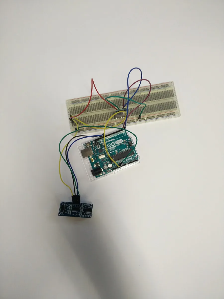
Concept
Seven layers of a robot's electronics
| Layer | Job | Typical parts | Lessons |
|---|---|---|---|
| 1. Power | Supply every rail safely | Battery/adapter, fuse, switch, regulators, capacitors | 2, 5, 14 |
| 2. Compute | Read, decide, command | UNO, ESP32, Pico, STM32 | 10, 11 |
| 3. Drive | Turn small signals into big currents | MOSFETs, H-bridges, servo/stepper drivers | 6, 9, 12 |
| 4. Actuate | Make motion | Servos, DC motors, steppers | 9, 12 |
| 5. Sense | Measure the world | Range sensors, IMUs, encoders, pots | 8, 12 |
| 6. Communicate | Move data between chips and people | UART, I²C, SPI, USB, Bluetooth | 13 |
| 7. Safety | Stop it when needed | E-stop that cuts actuator power, fuses, limits, watchdog | All |
Power is the foundation
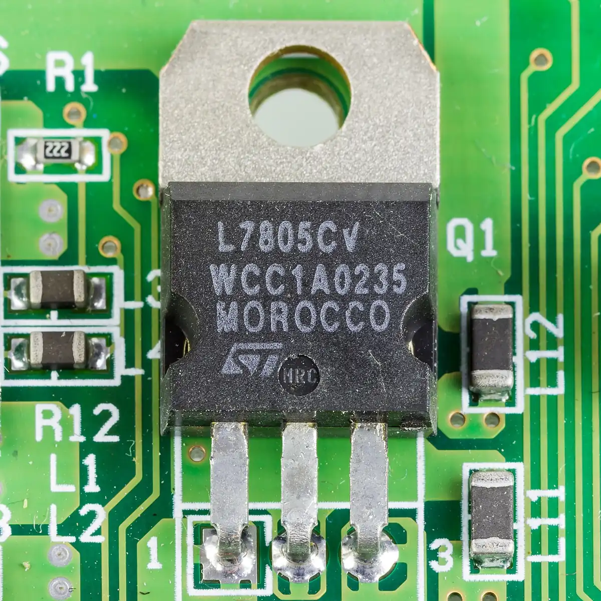
Split power into rails. The actuator rail feeds servos and motor drivers, sized for stall current with margin. The logic rail feeds the microcontroller and sensors — small, clean and stable. A 3.3 V rail feeds 3.3 V parts. All grounds meet (common ground), but motors never share the logic regulator.
A classic logic regulator is the 7805. TI's LM340 datasheet gives an output current of up to 1.5 A, a typical dropout of about 2 V at 1 A (so the input must stay roughly 2 V above 5 V), and thermal shutdown when the chip gets too hot. A linear regulator burns the extra voltage as heat:
P(heat) = (V_in − V_out) × I
- 9 V in, 5 V out, 0.133 A → about 0.53 W — fine
- 9 V in, 5 V out, 2.2 A → about 8.9 W — far beyond the 1.5 A rating; thermal shutdown
The signal path
Follow one command: the sensor sends a signal (level-shifted if needed) to the compute layer; the firmware decides; a PWM or bus command goes to a driver; the driver switches actuator-rail current into the actuator; and feedback returns through a sensor. Each arrow on your drawing should say what travels on it (voltage, PWM, I²C at an address, UART at a baud) and at what logic level.
Power tree
Plan the power tree
This planning script budgets the logic rail, checks a 7805 at different input voltages, shows what happens if someone hangs the servos on it, and prints a sane power tree.
"""power_tree.py - plan the power layer of a small robot (Stage 4, Lesson 14).

Pure Python planning tool. Facts used: TI LM340/LM7805 datasheet (output up to 1.5 A,
dropout about 2 V at 1 A, thermal shutdown near 150 C, input caps 0.22 uF / output 0.1 uF
in the test circuit). Linear regulator heat: P = (Vin - Vout) x I. Load currents below are
EXAMPLE values - replace them with your own measured or datasheet numbers.
"""

LOGIC_LOADS_MA = {
    "Arduino UNO-class board (example)": 50,
    "HC-SR04 ultrasonic": 15,
    "IMU breakout (3.3 V side, example)": 1,
    "Status LEDs x3": 27,
    "Bluetooth serial module (example)": 40,
}
ACTUATOR_LOADS_MA = {
    "Servo 1 (stall, example)": 700,
    "Servo 2 (stall, example)": 700,
    "Servo 3 (stall, example)": 700,
}

print("1) Logic rail (5 V) budget")
logic = sum(LOGIC_LOADS_MA.values())
for name, ma in LOGIC_LOADS_MA.items():
    print(f"   {name:<36} {ma:>5} mA")
print(f"   {'TOTAL logic':<36} {logic:>5} mA")

print("\n2) Feeding the logic rail from a 7805 linear regulator")
DROPOUT_V = 2.0
for vin in (6.0, 7.4, 9.0, 12.0):
    headroom = vin - 5.0
    heat_w = headroom * logic / 1000
    ok = headroom >= DROPOUT_V
    note = "OK" if ok else "BELOW DROPOUT - output will sag"
    print(f"   Vin {vin:>4.1f} V: headroom {headroom:.1f} V, heat {heat_w:.2f} W  {note}")
print("   Same 7805 feeding the servos too? See below.")

print("\n3) What if someone hangs the servos on the 7805 as well?")
act = sum(ACTUATOR_LOADS_MA.values())
total = logic + act
print(f"   logic {logic} mA + servos {act} mA = {total} mA")
print(f"   7805 rating is 1.5 A -> {'over the limit' if total > 1500 else 'within rating'} by {abs(total - 1500)} mA")
print(f"   heat at 9 V in: (9 - 5) x {total / 1000:.3f} A = {4 * total / 1000:.1f} W -> thermal shutdown, brownout, reset loops")

print("\n4) A sane power tree")
tree = [
    ("Battery / adapter", "main switch + fuse", ""),
    ("  -> Actuator rail", "5-6 V supply sized for stall", f"{act / 1000:.1f} A worst case x 1.25 = {act * 1.25 / 1000:.2f} A"),
    ("  -> Logic rail", "7805 or the board's regulator", f"{logic} mA"),
    ("  -> 3.3 V sensors", "board 3V3 pin or own regulator", "tiny"),
    ("Common ground", "all GND wires meet at one point", ""),
    ("E-stop", "cuts the ACTUATOR rail, not just software", ""),
]
for node, what, budget in tree:
    print(f"   {node:<20} {what:<36} {budget}".rstrip())
Output (run with python3 power_tree.py)
1) Logic rail (5 V) budget
   Arduino UNO-class board (example)       50 mA
   HC-SR04 ultrasonic                      15 mA
   IMU breakout (3.3 V side, example)       1 mA
   Status LEDs x3                          27 mA
   Bluetooth serial module (example)       40 mA
   TOTAL logic                            133 mA

2) Feeding the logic rail from a 7805 linear regulator
   Vin  6.0 V: headroom 1.0 V, heat 0.13 W  BELOW DROPOUT - output will sag
   Vin  7.4 V: headroom 2.4 V, heat 0.32 W  OK
   Vin  9.0 V: headroom 4.0 V, heat 0.53 W  OK
   Vin 12.0 V: headroom 7.0 V, heat 0.93 W  OK
   Same 7805 feeding the servos too? See below.

3) What if someone hangs the servos on the 7805 as well?
   logic 133 mA + servos 2100 mA = 2233 mA
   7805 rating is 1.5 A -> over the limit by 733 mA
   heat at 9 V in: (9 - 5) x 2.233 A = 8.9 W -> thermal shutdown, brownout, reset loops

4) A sane power tree
   Battery / adapter    main switch + fuse
     -> Actuator rail   5-6 V supply sized for stall         2.1 A worst case x 1.25 = 2.62 A
     -> Logic rail      7805 or the board's regulator        133 mA
     -> 3.3 V sensors   board 3V3 pin or own regulator       tiny
   Common ground        all GND wires meet at one point
E-stop cuts the ACTUATOR rail, not just softwareVisual
Visualise it: build the architecture until it's ready
This is the whole architecture as a checklist: actuator supply, common ground, MCU, driver, actuator on the driver's rails, sensor on the logic rail (or level-shifted) and clean signals. Build until the banner reads Embedded Robot Ready, then tick the unsafe GPIO-to-motor block and watch it break. Browser simulation only.
Interactive · Robot Electronics Wiring Lab
Assemble a full educational architecture: power, common ground, MCU, driver, actuators, sensors, and clean signal paths. Unlock Embedded Robot Ready.
- Missing: Dedicated low-voltage PSU for actuators
- Missing: Common ground MCU ↔ driver ↔ sensors
- Missing: MCU / embedded brain present
- Missing: Motor/servo driver between MCU and actuator
- …+3 more
Low-voltage educational sim · sims ≠ datasheets · never access real hardware from the browser.
Design review
Design review: catch the bugs on paper
This review tool checks a design against the seven layers and the rules from this stage. The DRAFT design has seven mistakes; the FIXED design has none. Read each line and find the lesson that taught it.
"""arch_check.py - check a robot design against the 7 architecture layers (Stage 4, Lesson 14).

Pure Python design-review tool, mirroring the checks in the course's wiring lab:
power, common ground, compute, driver, actuator, sensor logic level, signals, safety.
"""

LAYERS = ("power", "compute", "drive", "actuate", "sense", "communicate", "safety")


def review(design):
    issues = []
    have = {b["layer"] for b in design["blocks"]}
    for layer in LAYERS:
        if layer not in have:
            issues.append(f"missing layer: {layer}")
    names = {b["name"]: b for b in design["blocks"]}
    for a, b, kind in design["links"]:
        src, dst = names[a], names[b]
        if kind == "power" and src["layer"] == "compute" and dst["layer"] == "actuate":
            issues.append(f"{a} powers {b}: actuators need their own supply")
        if kind == "signal" and src["layer"] == "compute" and dst["layer"] == "actuate":
            if not dst.get("signal_only"):
                issues.append(f"{a} GPIO drives {b} directly: put a driver in between")
        if kind == "signal" and dst["layer"] == "compute" and src.get("volts", 0) > dst.get("logic_v", 5):
            issues.append(f"{a} sends {src['volts']} V into {dst['logic_v']} V {b}: level-shift it")
    grounds = design.get("ground_joined", [])
    for b in design["blocks"]:
        if b["layer"] in ("compute", "drive", "sense") and b["name"] not in grounds:
            issues.append(f"{b['name']} not on the common ground")
    addrs = {}
    for b in design["blocks"]:
        if "i2c" in b:
            if b["i2c"] in addrs:
                issues.append(f"I2C address clash 0x{b['i2c']:02X}: {addrs[b['i2c']]} and {b['name']}")
            addrs[b["i2c"]] = b["name"]
    if not any(b["layer"] == "safety" and b.get("cuts") == "actuator power" for b in design["blocks"]):
        issues.append("no stop that cuts actuator power (a software stop is not an e-stop)")
    return issues


draft = {
    "blocks": [
        {"name": "USB 5V", "layer": "power"},
        {"name": "ESP32", "layer": "compute", "logic_v": 3.3},
        {"name": "Servo", "layer": "actuate"},
        {"name": "HC-SR04", "layer": "sense", "volts": 5},
        {"name": "IMU", "layer": "sense", "i2c": 0x6B, "volts": 3.3},
        {"name": "OLED", "layer": "communicate", "i2c": 0x6B},
        {"name": "Stop button on GPIO", "layer": "safety", "cuts": "software flag"},
    ],
    "links": [
        ("ESP32", "Servo", "power"),
        ("ESP32", "Servo", "signal"),
        ("HC-SR04", "ESP32", "signal"),
        ("IMU", "ESP32", "signal"),
    ],
    "ground_joined": ["ESP32", "IMU"],
}

fixed = {
    "blocks": [
        {"name": "Battery + fuse", "layer": "power"},
        {"name": "ESP32", "layer": "compute", "logic_v": 3.3},
        {"name": "PCA9685", "layer": "drive", "i2c": 0x40},
        {"name": "Servo", "layer": "actuate", "signal_only": True},
        {"name": "HC-SR04 via divider", "layer": "sense", "volts": 3.3},
        {"name": "IMU", "layer": "sense", "i2c": 0x6B, "volts": 3.3},
        {"name": "Serial telemetry", "layer": "communicate"},
        {"name": "E-stop switch", "layer": "safety", "cuts": "actuator power"},
    ],
    "links": [
        ("ESP32", "PCA9685", "signal"),
        ("HC-SR04 via divider", "ESP32", "signal"),
        ("IMU", "ESP32", "signal"),
    ],
    "ground_joined": ["ESP32", "PCA9685", "HC-SR04 via divider", "IMU"],
}

for title, design in (("DRAFT design", draft), ("FIXED design", fixed)):
    issues = review(design)
    print(f"{title}: {len(issues)} issue(s)")
    for i in issues:
        print(f"   x {i}")
    if not issues:
        print("   all 7 layers present, power/ground/signals/driver/safety OK")
    print()
Output (run with python3 arch_check.py)
DRAFT design: 7 issue(s)
   x missing layer: drive
   x ESP32 powers Servo: actuators need their own supply
   x ESP32 GPIO drives Servo directly: put a driver in between
   x HC-SR04 sends 5 V into 3.3 V ESP32: level-shift it
   x HC-SR04 not on the common ground
   x I2C address clash 0x6B: IMU and OLED
   x no stop that cuts actuator power (a software stop is not an e-stop)

FIXED design: 0 issue(s)
   all 7 layers present, power/ground/signals/driver/safety OK
Real world
Where this architecture shows up
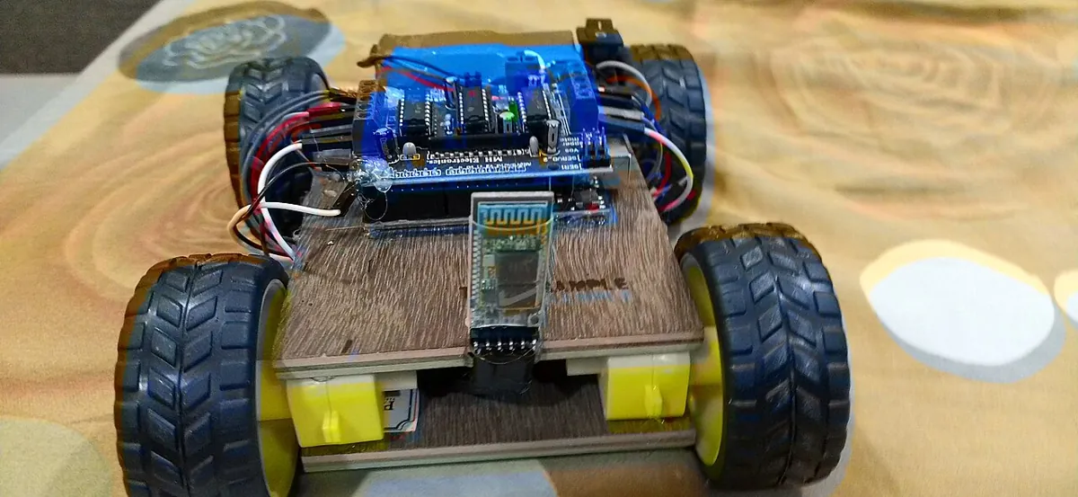
- Robot arms separate the motor power from the controller and wire an emergency stop that removes motor power.
- Rovers and drones run a power board that feeds a high-current actuator rail and regulated logic rails from one battery.
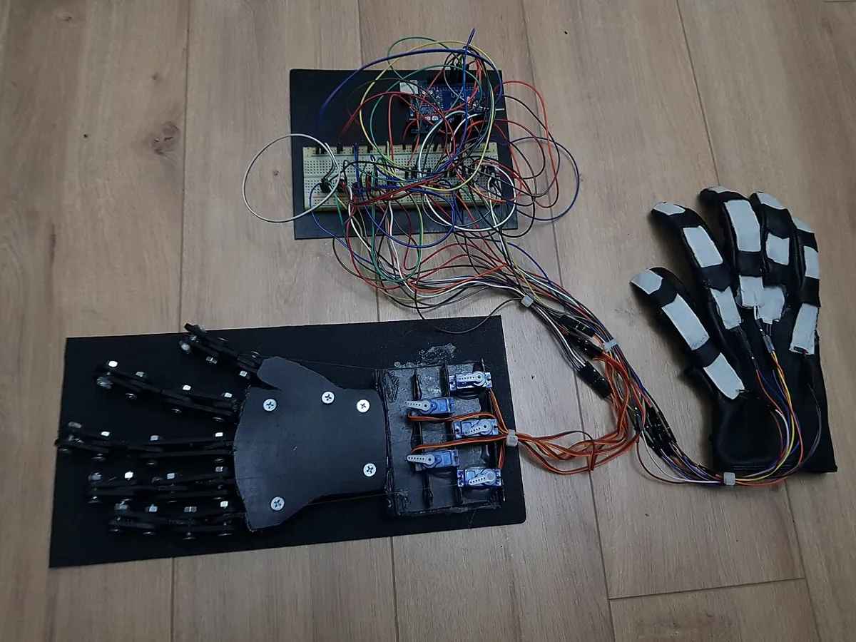
- Prosthetic and assistive hands use the same layers in a tiny space — sensors, a controller, motor drivers and careful power.
- Industrial machines document every layer in a one-page block diagram before build, exactly like your assignment.
Debugging
Debugging at the architecture level
| Symptom | Architecture cause | Fix |
|---|---|---|
| Board resets when motors start | Actuators on the logic regulator | Separate actuator rail; bulk capacitor |
| Regulator too hot to touch | Too much (Vin − Vout) × I | Lower Vin, a switching regulator, or less load |
| Logic rail sags at low battery | Input below the regulator's dropout | Higher-voltage pack or low-dropout regulator |
| Sensor readings jump when motors run | Shared ground return carrying motor current | Star ground: motor currents return separately to the supply |
| Robot keeps moving after a crash | Stop only in software | Hardware e-stop on the actuator rail |
Hardware & safety
Hardware lab and safety notes
This lesson is a design review, but you can check a real robot (or a kit) with only a multimeter — powered off first, then powered with the motors lifted off the ground.
- Powered off: use continuity mode to confirm every board’s GND is joined to the battery − at one point.
- Powered on, wheels/arm free: measure the logic rail and the actuator rail. Then move a servo and watch whether the logic rail dips.
- Press the e-stop and confirm it cuts the actuator rail, not just a software flag.
Think
Think about it
Think
Meera's rover runs a 7805 from a 6 V battery pack for the logic, and the servos from the same 7805 'because it's already there'. List every problem you can find.
Experiment
Try it in the lab: review a design
Be the design reviewer: use the wiring lab and the scripts to find and fix architecture mistakes.
Experiment
Review a design
You will need
- Robot wiring lab (in your browser)
- Notebook
- Optional: `power_tree.py` and `arch_check.py`
Steps
- Draw seven boxes for the layers. Fill them in for a two-wheel robot with a range sensor.
- Run `power_tree.py`. Copy the 7805 heat at 9 V and 12 V in.
- Run `arch_check.py`. For each of the seven DRAFT issues, write the lesson number that taught the rule.
- In the wiring lab, reach Embedded Robot Ready. Then untick common ground. What breaks?
- Draw where your e-stop sits in the power tree.
Interactive · Robot Electronics Wiring Lab
Assemble a full educational architecture: power, common ground, MCU, driver, actuators, sensors, and clean signal paths. Unlock Embedded Robot Ready.
- Missing: Dedicated low-voltage PSU for actuators
- Missing: Common ground MCU ↔ driver ↔ sensors
- Missing: MCU / embedded brain present
- Missing: Motor/servo driver between MCU and actuator
- …+3 more
Low-voltage educational sim · sims ≠ datasheets · never access real hardware from the browser.
Most robot failures are planned in, not coded in. A one-page architecture with rails, grounds, drivers, buses and a hardware stop removes them before the build.
Knowledge check
Check your understanding
Knowledge check
1. Which layer turns a PWM signal into motor current?
2. Why separate logic and actuator rails?
3. LM340/7805 maximum output current is about…
4. A 7805 drops 4 V at 0.5 A. Heat is…
5. Why is 6 V in too low for a 7805?
6. A real e-stop should…
7. An HC-SR04 Echo goes straight into an ESP32. Which layer rule is broken?
8. Two I²C parts both at 0x6B is a…
9. What should every arrow on your architecture drawing say?
10. Sensor readings jump whenever motors run. A likely cause is…
Mini assignment
Hands-on assignment
Mini assignment
One-page architecture for your robot
Draw the complete electrical architecture of your robot (or the 6DOF arm) on one page and review it.
Deliverables
- A block diagram with all seven layers and labelled arrows (signal type, bus, address/baud, voltage).
- A power tree: every rail, its source, its load in mA with a 25% margin, and the regulator heat where linear.
- The ground plan: where grounds meet, and how motor current returns.
- The e-stop: where it is and exactly what it cuts.
- Output of `arch_check.py` with your own design typed in.
Do this, step by step
- Draw your block diagram with all seven layers and label every arrow (signal type, bus, address/baud, voltage).
- Make the power tree: each rail, its source, its load in mA with 25% margin, and linear-regulator heat.
- Write the ground plan: where grounds meet and how motor current returns.
- Mark the e-stop and exactly what it cuts.
- Type your design into
arch_check.py, run it and fix every warning.
Stuck? Hints, one at a time
- Hint 1: The seven layers are Power, Compute, Drive, Actuate, Sense, Communicate and Safety — every block on your page should fit one of them.
- Hint 2: Linear regulator heat = (V_in − V_out) × I. From 12 V to 5 V at 0.5 A that is 3.5 W — far too hot for a bare 7805; use a buck converter.
- Hint 3: Motor current should return to the battery on its own thick wire, joining logic ground at one point (star ground).
- Hint 4: If
arch_check.pyflags the e-stop, check that it is on the actuator rail, before the drivers.
Challenges (pick by level)
- 🟢 Easy: Sort ten parts from this stage into the seven layers.
- 🟢 Easy: Work out 7805 heat at 12 V in and 300 mA.
- 🟡 Medium: Add a 3.3 V rail for an IMU and an OLED and size its regulator from datasheets.
- 🟠 Hard-ish: Compare a linear 7805 with a switching buck module for the same load. Use each one's datasheet efficiency.
- 🔴 Hard: Design the e-stop circuit with a relay that cuts the actuator rail, and its flyback diode (Lesson 6).
- ⚫ Expert: Add a watchdog and a 'heartbeat' between two microcontrollers so either one can cut actuator power if the other stops answering.
Next step
Time to put the whole stage together. In Lesson 15 — Capstone: Build a Virtual Robot Circuit you'll design, review and simulate a complete robot circuit: sensor, drivers, actuators, buses, power and a hardware stop.
Look back: Lesson 13: Serial Communication (UART/I2C/SPI). Next: Lesson 15: Capstone: Build a Virtual Robot Circuit. Related: Stage 0 — Anatomy of a Robot, Stage 6 — 6DOF Arm and later Stage 10 — ROS 2.
Sources
- TI LM340 / LM7805 datasheet — up to 1.5 A, ~2 V dropout at 1 A, thermal shutdown, 0.22 µF input capacitor in the test circuit.
- TI µA78xx datasheet — the same 78xx regulator family as the L7805 in the photo (ST’s own page blocks automated checks).
- SparkFun: Logic Levels — level shifting between 3.3 V and 5 V parts.
- Pololu A4988 and Adafruit PCA9685 servo driver — drivers between MCU and actuators.
- TI SLVA704 — Understanding the I²C bus — each device on a bus needs its own address.
- Arduino UNO R3 documentation — the compute board used in this stage.
- Photos: Wikimedia Commons (credits under each image).
Self-attested for now — keep artifacts in your lab notebook.
Complete
Today's goal
0 of 1 done today
Mark this lesson complete when you have worked the experiment, knowledge check, and assignment (even roughly).