
Electronics & Embedded Systems · Lesson 06
Diodes, MOSFETs & Electronic Switching
Est. 45–60 min
Why
Why a tiny pin can’t spin a motor — and what can
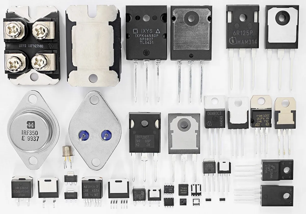
Until now every load you switched was gentle: an LED and its resistor, a button, a sensor. Robots also have heavy loads — DC motors, solenoids, relay coils, pumps, LED strips. They need far more current than a microcontroller pin can give, and many of them are coils that throw back a nasty voltage spike when you switch them off. This chapter teaches the two parts that solve both problems: the MOSFET, a switch controlled by voltage, and the diode, a one-way door for current.
By the end you will be able to: read a diode’s band and ratings, explain forward voltage and reverse blocking, wire an N-channel MOSFET as a low-side switch with a gate resistor and a gate pull-down, put a flyback diode the right way round across a motor or relay coil, read the five datasheet numbers that decide whether a MOSFET will survive, estimate how hot it will get, and explain why a 3.3 V board needs extra care.
Concept
Diodes and MOSFETs in plain words
Think of the water pump in many Indian homes. Under the pump there is a non-return valve: water can go up to the tank, but it cannot flow back down. That valve is a diode. Now think of the big municipal valve on the main pipeline. A worker does not lift the water himself — he only turns a small wheel, and the valve lets a huge flow through. That valve is a MOSFET: a tiny effort at the gate controls a big flow between drain and source.
The diode: a one-way door for current
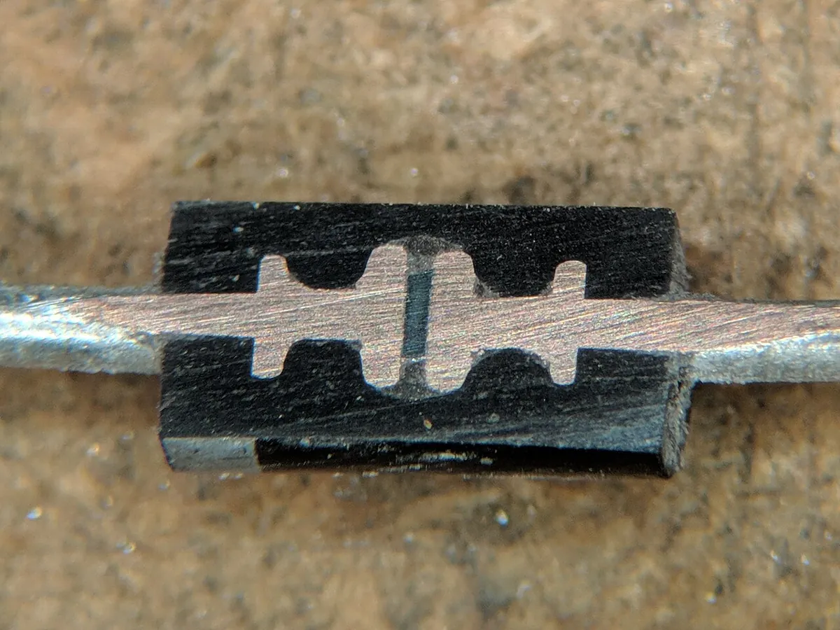
SparkFun explains that current through a diode can only go one way, the forward direction, from the anode to the cathode. Current trying to flow backwards is blocked. Two numbers describe a real diode. The forward voltage (VF) is the small voltage it “eats” while conducting — about 0.6–1 V for ordinary silicon diodes, about 0.3 V for germanium, and lower for Schottky diodes. The breakdown voltage is the reverse voltage at which it finally gives in and conducts backwards; a good design never goes near it.
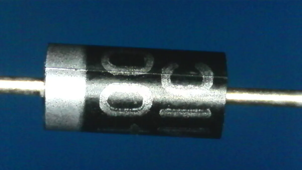
| Rating | 1N4007 | What it means for you |
|---|---|---|
| Max repetitive reverse voltage (VRRM) | 1000 V | It can block far more than any robot battery |
| Max average forward current (IF(AV)) | 1.0 A | Fine for flyback duty on small motors and relays |
| Peak surge current (IFSM, 8.3 ms) | 30 A | Survives short bursts, not continuous overloads |
| Max forward voltage (VF) at 1.0 A | 1.1 V | You lose up to about 1 V when it is in series |
| Max reverse current (IR) | 5 µA at 25 °C, 50 µA at 125 °C | Tiny leakage when blocking |
The MOSFET: a switch you control with voltage
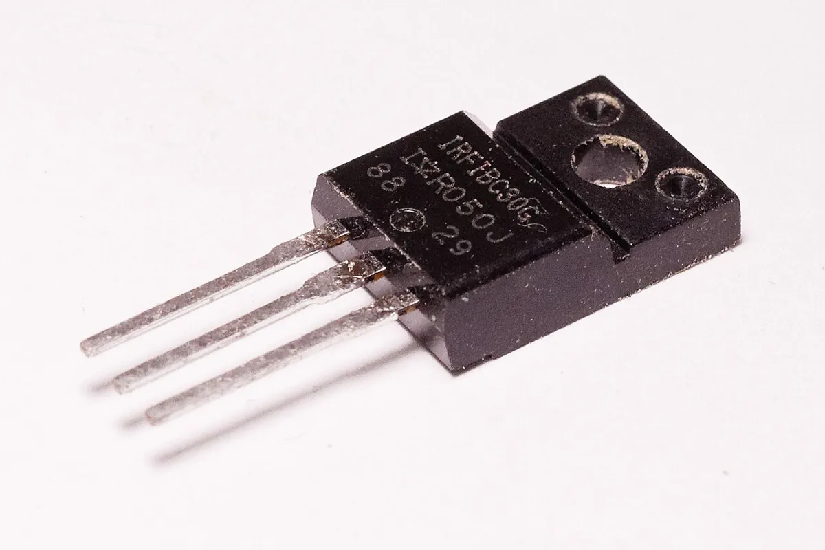
A MOSFET (metal-oxide-semiconductor field-effect transistor) has three legs: gate (G), drain (D) and source (S). In an N-channel MOSFET, raising the gate voltage above the source opens a channel, and current flows from drain to source. The gate is insulated by a thin oxide layer, so once it is charged it draws almost no current — the IRLZ44N datasheet lists a gate leakage of at most 100 nA. That is why a microcontroller pin, which can give only a few milliamps, can control amps through the drain.
SparkFun’s transistor tutorial uses the older BJT (like the NPN 2N2222 or Arduino’s TIP120 example), which is controlled by a small base current. It also notes that MOSFETs are more power-efficient. For robot switching we prefer a logic-level N-channel MOSFET, because it is controlled by voltage and wastes very little power when fully on.
P = I² × RDS(on)
- P = heat made inside the MOSFET while it is fully ON (watts)
- I = load current through drain and source (amps)
- RDS(on) = the MOSFET’s ON resistance, read from the datasheet AT YOUR GATE VOLTAGE
- Example (IRLZ44N, VGS 5 V, RDS(on) max 0.025 Ω): 1.5 A → 1.5² × 0.025 = 0.056 W — barely warm
| Parameter | Value | Why you care |
|---|---|---|
| Drain-source voltage VDSS | 55 V | Your supply plus any spike must stay below this |
| RDS(on) max | 0.022 Ω @ VGS 10 V · 0.025 Ω @ 5 V · 0.035 Ω @ 4 V | Lower gate voltage → higher resistance → more heat |
| Gate threshold VGS(th) | 1.0–2.0 V (at only 250 µA) | Where it STARTS to conduct — not where it is fully on |
| Gate-source voltage max | ±16 V | Never drive the gate from 24 V rails directly |
| Continuous drain current | 47 A with the case held at 25 °C | A lab-only best case; heat is the real limit |
| Thermal resistance, junction-to-air | 62 °C/W (no heatsink) | Each watt makes it about 62 °C hotter than the room |
| Package | TO-220 | Metal tab is connected to the drain — keep it away from other metal |
How it works
How it actually works: the low-side switch and its three helpers
The low-side switch
The simplest safe circuit puts the MOSFET on the low side — between the load and ground. The load’s + goes to its own supply, the load’s − goes to the MOSFET’s drain, and the source goes to ground. When the gate is HIGH the MOSFET connects the load to ground and current flows; when the gate is LOW the path is broken. Because the source sits at ground, the gate only needs a few volts above ground — exactly what a GPIO pin gives. SparkFun shows the same low-side idea with an NPN transistor, and explains that switching on the high side is harder when the load voltage (say 12 V) is higher than the control voltage (5 V).
Separate supply for the load
Motor + goes to a battery pack or adapter sized for the motor’s stall current — never to a GPIO pin or the Arduino’s 5V pin.
MOSFET on the low side
Motor − to DRAIN, SOURCE to the supply’s −. Short, thick wires on this high-current loop.
Common ground
One wire from the supply’s − to the Arduino GND, so the gate voltage has a reference. Without it the MOSFET never sees a clean HIGH.
Gate resistor (100–220 Ω)
Between the pin and the gate. It limits the brief charging current into the gate (see the script below) and damps ringing.
Gate pull-down (10 kΩ)
From gate to ground. At power-up and during reset, Arduino pins are high-impedance inputs; the pull-down holds the MOSFET firmly OFF so the motor can’t twitch.
Flyback diode
1N4007 or 1N4001 across the motor (or relay coil), band (cathode) to the supply +. Normally it blocks; it only conducts when the coil kicks back.
Why coils kick back
A motor, relay or solenoid is a coil of wire — an inductor. An inductor stores energy in its magnetic field and hates sudden changes of current. When the MOSFET switches off, the current wants to keep flowing for a moment, and the coil produces whatever voltage it takes to push it: V = L × di/dt. A fast switch means a big di/dt and a big spike — easily many times the supply voltage. Without a path, that spike lands on the MOSFET’s drain.
V = L × di/dt
- L = coil inductance (henry), di/dt = how fast the current changes (amps per second)
- Example: 10 mH carrying 0.5 A, switched off in 10 µs → 0.01 × 0.5 ÷ 0.00001 = 500 V (ideal, no diode)
- With a flyback diode the coil’s current simply circulates through the diode and fades away
SparkFun describes the flyback diode exactly this way: placed across the inductive load, it gives the negative spike a safe path, and the current loops through the coil and the diode until it dies out. Arduino’s own transistor motor tutorial puts a 1N4001 across the motor leads with the stripe towards the supply + for the same reason: to keep the electricity the motor generates from damaging the circuit.
Reverse-polarity protection: the diode’s other job
SparkFun also shows a diode in series with a supply input. If someone plugs the battery in backwards, the diode blocks and the circuit survives. The cost is the forward voltage: with a 1N4007 you may lose up to about 1.1 V at 1 A (Vishay datasheet). On a 5 V rail that is a lot; on a 12 V motor rail it is usually acceptable. Schottky diodes lose less.
Datasheet check
Will it survive? Five datasheet checks before you switch anything
| Check | Ask yourself | IRLZ44N on a 12 V, 1.5 A motor |
|---|---|---|
| 1. Voltage | Is VDS(max) comfortably above my supply plus spikes? | 55 V vs 12 V — yes, with a flyback diode fitted |
| 2. Gate drive | Is RDS(on) specified at MY gate voltage? | 5 V Uno: yes (0.025 Ω). 3.3 V board: not specified — choose another part |
| 3. Heat | P = I² × RDS(on). P × 62 °C/W = rise without a heatsink. OK? | 1.5² × 0.025 ≈ 0.056 W → about 3.5 °C rise. Easy |
| 4. Gate limit | Will VGS ever exceed ±16 V? | No — the gate sees 0 or 5 V |
| 5. Diode | Is the flyback diode rated for the supply voltage and the coil current? | 1N4007: 1000 V, 1 A average, 30 A surge — fine |
Visual
Visualise it: safe and unsafe ways to switch a motor
Press **Safe: PWM → driver → motor** and move the DC motor slider: the pin only sends a signal, the driver (a MOSFET or H-bridge) carries the current. Then press **Bad: GPIO-direct motor** and read the fault panel — stall current in amps vs a pin’s milliamps, and the inductive kick that a flyback diode would catch. Browser simulation only; it never drives real hardware.
Interactive · Motor & Servo Bench
Compare a safe path (PWM → driver → motor, common ground, separate power) vs the dangerous habit of driving a motor from a bare GPIO pin. Simulated only.
DC motor (via driver)
Driver handles current. MCU only sends logic-level PWM. Common ground required.
Servo (pulse width)
Servo needs dedicated 5–6 V power + signal from MCU. Soft limits before multi-joint arms.
Code lab
Code lab: check loads, heat and coil kicks with Python
1. Can the pin drive it? How hot will the MOSFET get?
This script compares common loads with what an ATmega328P pin can give (40 mA absolute maximum — the datasheet specifies its output voltages at 20 mA), computes MOSFET heat at three gate voltages from the IRLZ44N datasheet, shows what a series diode costs you, and estimates the gate charging current through different gate resistors.
# switch_toolkit.py — can a GPIO pin drive this load, or does it need a MOSFET?
# Stage 4, Lesson 6. Simulation only: arithmetic and prints. No pins, no ports, no hardware.

GPIO_ABS_MAX_A = 0.040      # ATmega328P: 40 mA per I/O pin is the ABSOLUTE MAXIMUM, not a target
GPIO_COMFORT_A = 0.020      # the datasheet's VOH/VOL lines are specified at 20 mA — a sensible ceiling

# IRLZ44N (Infineon datasheet) maximum RDS(on) at each gate voltage
IRLZ44N_RDS_ON = {10.0: 0.022, 5.0: 0.025, 4.0: 0.035}
IRLZ44N_VGS_TH = (1.0, 2.0)  # threshold min..max, measured at only 250 uA of drain current
R_THETA_JA = 62              # deg C per watt, TO-220 with no heatsink


def verdict(name, amps):
    if amps <= GPIO_COMFORT_A:
        return f"{name:<28} {amps*1000:8.3f} mA -> OK straight from a GPIO pin (with a series resistor)"
    if amps <= GPIO_ABS_MAX_A:
        return f"{name:<28} {amps*1000:8.3f} mA -> risky: too close to the 40 mA absolute maximum"
    return f"{name:<28} {amps*1000:8.3f} mA -> NEVER from a GPIO pin: use a MOSFET / driver"


print("1) Load current vs what a pin can give")
print("-" * 72)
loads = [   # example loads — measure YOUR parts; these are typical classroom numbers
    ("Red LED + 220 ohm at 5 V", (5.0 - 2.0) / 220),
    ("Logic input of a driver", 0.000001),
    ("Small 5 V relay coil (70 ohm)", 5.0 / 70),
    ("Hobby DC motor, running", 0.25),
    ("Hobby DC motor, stalled", 1.5),
    ("12 V LED strip, 1 m", 0.6),
]
for name, amps in loads:
    print(" ", verdict(name, amps))

print()
print("2) IRLZ44N as a low-side switch: heat in the MOSFET = I^2 x RDS(on)")
print("-" * 72)
for vgs, rds in IRLZ44N_RDS_ON.items():
    for amps in (0.5, 1.5, 3.0):
        p = amps ** 2 * rds
        rise = p * R_THETA_JA
        print(f"  VGS {vgs:4.1f} V  I = {amps:3.1f} A  RDS(on) {rds*1000:4.0f} mOhm "
              f"-> {p*1000:6.1f} mW, about {rise:4.1f} C above room, no heatsink")
print(f"  VGS(th) is only {IRLZ44N_VGS_TH[0]}-{IRLZ44N_VGS_TH[1]} V at 250 uA: 'just starting', NOT fully on.")
print("  At 3.3 V the datasheet gives no RDS(on) line -> pick a MOSFET rated at your gate voltage.")

print()
print("3) Diode drop: what a series protection diode costs you")
print("-" * 72)
for name, vf in (("1N4007 (max VF at 1 A)", 1.1), ("typical silicon", 0.7)):
    for supply in (5.0, 6.0, 12.0):
        print(f"  {name:<24} supply {supply:4.1f} V -> load gets about {supply - vf:4.1f} V")

print()
print("4) Gate charge: how much current does the pin push to switch the MOSFET?")
print("-" * 72)
QG_MAX = 48e-9   # IRLZ44N total gate charge, max, at VGS = 5 V
for r_gate in (100, 220, 470):
    i_peak = 5.0 / r_gate
    t_est = QG_MAX / (i_peak / 2)            # rough: average current about half the peak
    print(f"  gate resistor {r_gate:3d} ohm -> peak {i_peak*1000:5.1f} mA, switches in roughly {t_est*1e6:4.1f} us")
print("  Short pulses only; the gate draws almost nothing once charged (leakage <= 100 nA).")
Output (run with python3 switch_toolkit.py)
1) Load current vs what a pin can give
------------------------------------------------------------------------
  Red LED + 220 ohm at 5 V       13.636 mA -> OK straight from a GPIO pin (with a series resistor)
  Logic input of a driver         0.001 mA -> OK straight from a GPIO pin (with a series resistor)
  Small 5 V relay coil (70 ohm)   71.429 mA -> NEVER from a GPIO pin: use a MOSFET / driver
  Hobby DC motor, running       250.000 mA -> NEVER from a GPIO pin: use a MOSFET / driver
  Hobby DC motor, stalled      1500.000 mA -> NEVER from a GPIO pin: use a MOSFET / driver
  12 V LED strip, 1 m           600.000 mA -> NEVER from a GPIO pin: use a MOSFET / driver

2) IRLZ44N as a low-side switch: heat in the MOSFET = I^2 x RDS(on)
------------------------------------------------------------------------
  VGS 10.0 V  I = 0.5 A  RDS(on)   22 mOhm ->    5.5 mW, about  0.3 C above room, no heatsink
  VGS 10.0 V  I = 1.5 A  RDS(on)   22 mOhm ->   49.5 mW, about  3.1 C above room, no heatsink
  VGS 10.0 V  I = 3.0 A  RDS(on)   22 mOhm ->  198.0 mW, about 12.3 C above room, no heatsink
  VGS  5.0 V  I = 0.5 A  RDS(on)   25 mOhm ->    6.2 mW, about  0.4 C above room, no heatsink
  VGS  5.0 V  I = 1.5 A  RDS(on)   25 mOhm ->   56.2 mW, about  3.5 C above room, no heatsink
  VGS  5.0 V  I = 3.0 A  RDS(on)   25 mOhm ->  225.0 mW, about 14.0 C above room, no heatsink
  VGS  4.0 V  I = 0.5 A  RDS(on)   35 mOhm ->    8.8 mW, about  0.5 C above room, no heatsink
  VGS  4.0 V  I = 1.5 A  RDS(on)   35 mOhm ->   78.8 mW, about  4.9 C above room, no heatsink
  VGS  4.0 V  I = 3.0 A  RDS(on)   35 mOhm ->  315.0 mW, about 19.5 C above room, no heatsink
  VGS(th) is only 1.0-2.0 V at 250 uA: 'just starting', NOT fully on.
  At 3.3 V the datasheet gives no RDS(on) line -> pick a MOSFET rated at your gate voltage.

3) Diode drop: what a series protection diode costs you
------------------------------------------------------------------------
  1N4007 (max VF at 1 A)   supply  5.0 V -> load gets about  3.9 V
  1N4007 (max VF at 1 A)   supply  6.0 V -> load gets about  4.9 V
  1N4007 (max VF at 1 A)   supply 12.0 V -> load gets about 10.9 V
  typical silicon          supply  5.0 V -> load gets about  4.3 V
  typical silicon          supply  6.0 V -> load gets about  5.3 V
  typical silicon          supply 12.0 V -> load gets about 11.3 V

4) Gate charge: how much current does the pin push to switch the MOSFET?
------------------------------------------------------------------------
  gate resistor 100 ohm -> peak  50.0 mA, switches in roughly  1.9 us
  gate resistor 220 ohm -> peak  22.7 mA, switches in roughly  4.2 us
  gate resistor 470 ohm -> peak  10.6 mA, switches in roughly  9.0 us
  Short pulses only; the gate draws almost nothing once charged (leakage <= 100 nA).
2. The coil’s kick, with and without a flyback diode
This script uses V = L × di/dt to show the spike when a 10 mH coil carrying 0.5 A is switched off quickly with no diode, then steps through time to show the current fading through a flyback diode instead. It is a simple model (the diode drop is held constant), but the lesson is real: no diode, big spike; diode, gentle fade.
# flyback_sim.py — what a coil does when you switch it off, with and without a flyback diode.
# Stage 4, Lesson 6. Simulation only: a simple step-by-step model. No pins, no hardware.

V_SUPPLY = 12.0     # motor / relay supply (V)
L = 0.010           # coil inductance, 10 mH (illustrative value)
R_COIL = 24.0       # coil resistance (ohm) -> steady current 0.5 A
I_ON = V_SUPPLY / R_COIL
VF_DIODE = 1.1      # 1N4007 maximum forward voltage at 1 A (Vishay datasheet); held constant here to keep the model simple
V_BREAKDOWN = 55.0  # IRLZ44N drain-source breakdown (Infineon datasheet)

print(f"Coil: L = {L*1000:.0f} mH, R = {R_COIL:.0f} ohm, current while ON = {I_ON:.2f} A")
print()
print("1) No diode: the switch opens in t_off and the coil insists on keeping its current")
print("-" * 72)
for t_off in (100e-6, 10e-6, 1e-6):
    v_kick = L * I_ON / t_off          # V = L x di/dt
    note = "MOSFET breaks down / avalanches!" if V_SUPPLY + v_kick > V_BREAKDOWN else "within rating"
    print(f"  switch off in {t_off*1e6:6.1f} us -> V = L x di/dt = {v_kick:7.0f} V spike  ({note})")
print("  Real circuits clip this at some breakdown voltage — usually your transistor's.")

print()
print("2) With a flyback diode across the coil: the current circulates and fades safely")
print("-" * 72)
tau = L / R_COIL
print(f"  Drain voltage is clamped near {V_SUPPLY:.0f} + {VF_DIODE} = {V_SUPPLY + VF_DIODE:.1f} V")
print(f"  Decay time constant tau = L / R = {tau*1000:.3f} ms")
DT = 1e-6
i, t, next_print = I_ON, 0.0, 0.0
while t <= 5 * tau + DT:
    if t >= next_print - 1e-12:
        print(f"    t = {t*1000:5.3f} ms   coil current = {i:5.3f} A")
        next_print += tau
    di = -(i * R_COIL + VF_DIODE) / L * DT    # coil drives current through its own R and the diode
    i = max(0.0, i + di)
    t += DT
print("  The energy (1/2 L I^2) is burnt in the coil's resistance and the diode, not in your MOSFET.")
print(f"  Stored energy = {0.5 * L * I_ON**2 * 1000:.2f} mJ")
Output (run with python3 flyback_sim.py)
Coil: L = 10 mH, R = 24 ohm, current while ON = 0.50 A

1) No diode: the switch opens in t_off and the coil insists on keeping its current
------------------------------------------------------------------------
  switch off in  100.0 us -> V = L x di/dt =      50 V spike  (MOSFET breaks down / avalanches!)
  switch off in   10.0 us -> V = L x di/dt =     500 V spike  (MOSFET breaks down / avalanches!)
  switch off in    1.0 us -> V = L x di/dt =    5000 V spike  (MOSFET breaks down / avalanches!)
  Real circuits clip this at some breakdown voltage — usually your transistor's.

2) With a flyback diode across the coil: the current circulates and fades safely
------------------------------------------------------------------------
  Drain voltage is clamped near 12 + 1.1 = 13.1 V
  Decay time constant tau = L / R = 0.417 ms
    t = 0.000 ms   coil current = 0.500 A
    t = 0.417 ms   coil current = 0.155 A
    t = 0.834 ms   coil current = 0.028 A
    t = 1.250 ms   coil current = 0.000 A
    t = 1.667 ms   coil current = 0.000 A
    t = 2.084 ms   coil current = 0.000 A
  The energy (1/2 L I^2) is burnt in the coil's resistance and the diode, not in your MOSFET.
Stored energy = 1.25 mJReal world
Where diodes and MOSFETs do the heavy lifting
- Robot grippers and wheels: a microcontroller pin drives a MOSFET or a motor-driver chip; the driver carries the motor current from a separate battery.
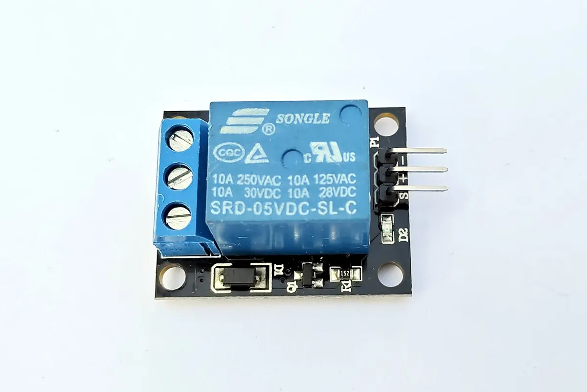
- Relay modules: a transistor drives the relay coil, and a diode across the coil catches the kick — the same pattern you built today, already on a small board.
- Solenoid locks and valves: a solenoid is a coil, so it gets a MOSFET and a flyback diode, exactly like a motor.
- Battery inputs: a series diode (or a smarter MOSFET circuit) protects robots from a battery plugged in backwards, as SparkFun describes.
- Motor drivers and H-bridges: four switches let a motor run both ways — Lesson 9 builds on today’s single switch.
- 3D printers and LED strips: heaters, fans and 12 V LED strips are commonly switched with MOSFETs controlled by low-voltage logic.
Bench build
Bench build: a button-controlled, MOSFET-switched DC motor
Only after the simulations make sense, build this on a breadboard with a small hobby DC motor (the kind in Arduino kits), an IRLZ44N, a 1N4007 or 1N4001, a 220 Ω and a 10 kΩ resistor, a push button and a separate 4×AA (about 6 V) battery pack.
Power OFF, plan first
Draw the circuit. Mark the motor supply loop (thick lines) and the logic loop (thin lines). They meet only at the common ground.
MOSFET and diode
Insert the IRLZ44N (leads 1-2-3 = G-D-S, printed face towards you). Motor − to D, S to the battery −. Diode across the motor, band to battery +.
Gate network
Pin 5 → 220 Ω → G. 10 kΩ from G to GND. Battery − to Arduino GND.
Button
Pin 2 → button → GND. The sketch uses INPUT_PULLUP, so pressed reads LOW.
Check before power
Use the table below with a multimeter. Only then connect the battery and USB.
Run and observe
Upload the sketch, open the Serial Monitor, press the button. The motor runs while held, for at most 3 s. Touch the MOSFET — it should be barely warm.
// mosfet_motor.ino — switch a small DC motor with a logic-level MOSFET (Stage 4, Lesson 6)
// For a REAL board on your bench. This sketch is not run inside the browser.
// Power:  motor (+) -> external motor supply (+), e.g. a 6 V AA pack. NEVER the Arduino 5V pin.
//         motor (-) -> MOSFET DRAIN.  MOSFET SOURCE -> motor supply (-).
//         Motor supply (-) -> Arduino GND (common ground).
// Diode:  1N4007/1N4001 ACROSS the motor, striped end (cathode) to motor supply (+).
// Gate:   Arduino pin 5 -> 220 Ohm -> GATE, and 10 kOhm from GATE to GND (keeps it OFF at reset).
// Button: pin 2 -> push button -> GND (uses INPUT_PULLUP from Lesson 4).

const int GATE_PIN = 5;
const int BUTTON_PIN = 2;
const unsigned long MAX_RUN_MS = 3000;   // safety: never run longer than 3 s per press

void setup() {
  pinMode(GATE_PIN, OUTPUT);
  digitalWrite(GATE_PIN, LOW);           // motor OFF first, always
  pinMode(BUTTON_PIN, INPUT_PULLUP);     // released = HIGH, pressed = LOW
  Serial.begin(9600);
  Serial.println("Press the button to run the motor (max 3 s).");
}

void loop() {
  if (digitalRead(BUTTON_PIN) == LOW) {
    unsigned long start = millis();
    digitalWrite(GATE_PIN, HIGH);        // MOSFET ON -> motor current flows supply -> motor -> drain -> source
    Serial.println("motor ON");
    while (digitalRead(BUTTON_PIN) == LOW && millis() - start < MAX_RUN_MS) {
      // keep running while the button is held, up to the time limit
    }
    digitalWrite(GATE_PIN, LOW);         // MOSFET OFF -> the diode catches the coil's kick
    Serial.print("motor OFF after ");
    Serial.print(millis() - start);
    Serial.println(" ms");
    delay(300);                          // crude debounce + rest
  }
}| Check | Meter mode | Power | What you expect |
|---|---|---|---|
| Diode direction | Diode test | OFF | A few hundred millivolts one way (red probe on the anode), “OL” the other way; band to battery + |
| Gate pull-down | Resistance, G to GND | OFF | About 10 kΩ |
| No short on the motor loop | Continuity, battery + to − | OFF | No beep |
| Common ground | Continuity, battery − to Arduino GND | OFF | Beep |
| Gate voltage | DC volts, G to GND | ON | About 0 V released, close to 5 V pressed |
| Drain voltage | DC volts, D to GND | ON | Near battery voltage when OFF, close to 0 V when ON |
Debugging
Debugging: when the motor won’t behave
| Symptom | Likely cause | Fix |
|---|---|---|
| Motor never runs, gate shows 5 V | No common ground, or drain and source swapped | Join battery − to Arduino GND; recheck the G-D-S pinout |
| Motor runs weakly, MOSFET hot | A standard (not logic-level) MOSFET, or only 3.3 V of gate drive | Use a logic-level MOSFET rated at your gate voltage |
| Motor twitches at power-up or reset | Gate floating while the pin is an input | Fit the 10 kΩ gate-to-ground pull-down |
| Board resets when the motor stops | Coil kick with no diode, or motor on the logic supply | Fit the flyback diode; give the motor its own supply |
| Battery gets hot the moment you switch on | Flyback diode fitted backwards (shorting the supply) | Disconnect at once; turn the diode round, band to + |
| Motor runs all the time | MOSFET damaged (often by a missing diode) or drain-source short | Replace the MOSFET and add the diode |
Think
Think about it
Think
Arjun moves his gripper project to a 3.3 V board. He keeps the IRLZ44N because “its threshold is only 1–2 V, so 3.3 V is double that”. The gripper motor stalls at about 3 A when it grips. Will it work well? What would you check first?
Experiment
Try it in the lab: switch a motor the safe way
Twenty minutes with the Motor & Servo Bench, the two Python scripts and your notebook. You will see the unsafe circuit fail, design the safe one, and prove it with numbers.
Experiment
Safe switching plan
You will need
- Motor & Servo Bench (below, runs in your browser)
- Notebook or a text file
- Optional: your laptop to run `switch_toolkit.py` and `flyback_sim.py`
Steps
- In the bench, press **Bad: GPIO-direct motor**. Copy the fault panel’s points into your notebook in your own words.
- Press **Safe: PWM → driver → motor**. Draw the safe circuit as a low-side MOSFET switch: supply, motor, drain, source, ground, gate resistor, gate pull-down, flyback diode, common ground.
- On your drawing, mark which wires carry the big motor current (thick) and which carry only the signal (thin).
- Run `switch_toolkit.py`. For a 1.5 A load at VGS 5 V, copy the MOSFET heat and temperature rise. Repeat for 3 A at 4 V.
- Run `flyback_sim.py`. Copy the spike voltage at 10 µs and the clamped voltage with a diode. Write one sentence: why does the diode save the MOSFET?
- Change `t_off` values or `L` in the script, run again, and write what changed.
Interactive · Motor & Servo Bench
Compare a safe path (PWM → driver → motor, common ground, separate power) vs the dangerous habit of driving a motor from a bare GPIO pin. Simulated only.
DC motor (via driver)
Driver handles current. MCU only sends logic-level PWM. Common ground required.
Servo (pulse width)
Servo needs dedicated 5–6 V power + signal from MCU. Soft limits before multi-joint arms.
A pin is a messenger, not a muscle. The MOSFET carries the current, the separate supply provides it, the common ground lets the order be understood, and the diode gives the coil’s stored energy somewhere safe to go.
Knowledge check
Check your understanding
Knowledge check
1. Which way does current flow through a diode in normal (forward) use?
2. A 1N4007 is placed in series with a 5 V supply for reverse-polarity protection. Roughly what can the load lose at 1 A?
3. Why should a hobby DC motor never be driven straight from an Arduino pin?
4. In a low-side MOSFET switch, where does the motor’s − wire go?
5. The flyback diode across a motor is fitted with its band (cathode) towards…
6. Why add a 10 kΩ resistor from the MOSFET gate to ground?
7. The IRLZ44N lists VGS(th) = 1.0–2.0 V. What does that tell you?
8. An IRLZ44N at VGS 5 V (RDS(on) 0.025 Ω) carries 2 A. How much heat is made in it?
9. Your motor circuit has a MOSFET and diode but the motor never runs, though the gate measures 5 V relative to the Arduino GND. What is the most likely missing wire?
10. Why can a coil produce hundreds of volts when switched off quickly?
Mini assignment
Hands-on assignment
Mini assignment
Switching plan for your robot’s gripper
Design, justify and (if you have the parts) build a safe switch for one heavy load on your robot — a gripper motor, a pump, a solenoid or a relay — using a logic-level MOSFET and a flyback diode.
Deliverables
- A neat circuit drawing: supply, load, MOSFET (G, D, S labelled), gate resistor, gate pull-down, flyback diode with band direction, common ground. Thick lines for high current, thin for signal.
- A load sheet: your load’s voltage, running current and stall current (from its label, datasheet or your own meter reading).
- A five-check datasheet table for your chosen MOSFET (voltage, RDS(on) at your gate voltage, heat, gate limit, diode) like the one in this chapter, with the datasheet link.
- Output of `switch_toolkit.py` and `flyback_sim.py` with your own load added, and one sentence on what each number means.
- If you build it: a photo of your breadboard and the six meter readings from the bench table.
- Half a page in your own words: “why the pin is a messenger, not a muscle”.
Do this, step by step
- Pick one heavy load on your robot (gripper motor, pump, solenoid or relay) and write its voltage, running current and stall current.
- Draw the low-side switch: supply, load, MOSFET (G, D, S), gate resistor, gate pull-down, flyback diode (band towards +), common ground.
- Fill the five-check table for your MOSFET from its datasheet.
- Add your load to
switch_toolkit.pyandflyback_sim.py, run both and paste the outputs. - If you have parts: build it with the motor on its own supply and take the six meter readings from the bench table.
Stuck? Hints, one at a time
- Hint 1: The MOSFET must be logic-level: look for RDS(on) given at VGS = 4.5 V or 5 V (or lower for 3.3 V boards), not only at 10 V.
- Hint 2: Heat in the MOSFET is P = I² × RDS(on). For the IRLZ44N at VGS 5 V (0.025 Ω max) and 2 A that is 2² × 0.025 = 0.1 W — no heatsink needed.
- Hint 3: The diode’s band (cathode) goes to the + supply side of the motor; the other end to the drain.
- Hint 4: A 10 kΩ gate pull-down keeps the motor off while the board is booting and the pin is still floating.
Challenges (pick by level)
- 🟢 Easy: Pick up a 1N4007. Which leg is the cathode? Draw the diode symbol and label anode and cathode. *Hint 1:* look for the band. *Hint 2:* the bar in the symbol is on the band’s side.
- 🟢 Easy: A red LED + 220 Ω on 5 V needs about 13.6 mA. Can a pin drive it directly? *Hint:* compare with 20 mA and 40 mA.
- 🟡 Medium: A 12 V LED strip draws 2 A. Compute the IRLZ44N heat at VGS 5 V and its temperature rise without a heatsink. *Hint 1:* P = I² × RDS(on). *Hint 2:* multiply by 62 °C/W.
- 🟡 Medium: Explain why a 1N4148 (about 200 mA, per SparkFun) is a poor flyback diode for a 1 A motor, but fine for a tiny relay. *Hint:* the diode carries the coil’s current for a moment.
- 🟠 Hard-ish: Change
flyback_sim.pyso the diode drop falls with current (for example 0.7 V below 0.1 A). How does the fade change? *Hint:* replace the constantVF_DIODEwith a small function ofi. - 🔴 Hard: Find a logic-level N-channel MOSFET whose datasheet specifies RDS(on) at 2.5 V or 3.3 V. Fill the five-check table for a 3 A motor on a 3.3 V board. *Hint:* search a distributor’s parametric filter for “VGS rated 2.5 V”, then always read the datasheet itself.
- ⚫ Expert: Draw a high-side switch for the same motor using a P-channel MOSFET, and explain why its gate needs to be pulled to the motor supply, not to 5 V. *Hint:* re-read SparkFun’s note on high-side switching when the load voltage is higher than the control voltage.
Next step
You can now switch heavy loads safely. In Lesson 7 — Digital Signals & GPIO you will look closely at the pin itself: what voltages count as HIGH and LOW, why 3.3 V and 5 V boards need care when they talk, how to read limit switches and e-stops reliably, and how to turn pin changes into robot events.
Tip: if you can explain today’s chapter with the pump picture — “the diode is the non-return valve, the MOSFET is the big valve a small wheel controls, and the coil is water that keeps rushing after you shut the tap” — you have truly understood it.
Look back: Lesson 5: Capacitors & Power Stability. Next: Lesson 7: Digital Signals & GPIO. Related: Stage 0 — Actuators and later Stage 7 — Control Systems.
Sources
- Vishay 1N4001–1N4007 datasheet — VRRM 1000 V, IF(AV) 1.0 A, IFSM 30 A, VF max 1.1 V at 1 A, reverse current.
- Infineon IRLZ44NPbF datasheet — logic-level gate drive, VDSS 55 V, RDS(on) at 10/5/4 V, VGS(th), VGS ±16 V, 62 °C/W, gate charge and leakage.
- SparkFun Learn: Diodes — forward voltage, breakdown, 1N4148 ratings, reverse-protection and flyback diodes.
- SparkFun Learn: Transistors — low-side and high-side switching, BJTs vs MOSFETs.
- Arduino: Transistor Motor Control — 40 mA pin limit, TIP120 with a 1N4001 across the motor, stripe to supply +, common ground.
- Arduino: Digital Pins — pins start as high-impedance inputs; 40 mA is not enough for relays, solenoids or motors.
- Adafruit Arduino Lesson 13: DC Motors — kit motor current vs larger motors, diode stripe towards the + supply.
- Microchip ATmega48A/PA/88A/PA/168A/PA/328/P datasheet — 40 mA absolute maximum per I/O pin; output levels specified at 20 mA.
- Photos: Wikimedia Commons (credits under each image).
Self-attested for now — keep artifacts in your lab notebook.
Complete
Today's goal
0 of 1 done today
Mark this lesson complete when you have worked the experiment, knowledge check, and assignment (even roughly).