
Electronics & Embedded Systems · Lesson 13
Serial Communication (UART/I2C/SPI intro)
Est. 50–65 min
Why
Why chips need a common language
So far each part had its own wire: one pin for a button, one for a servo. But an IMU has dozens of registers, a GPS sends whole sentences, and an SD card moves blocks of data. For that, chips send bits one after another on a few wires — serial communication. Three buses cover almost everything on a hobby robot: UART, I²C and SPI.
By the end you will be able to: draw a UART frame and explain “9600 8N1”; wire TX to RX correctly; explain why a baud mismatch gives garbage; trace an I²C read with START, address, ACK and STOP; tell a 7-bit address from the 8-bit form in datasheets; size I²C pull-ups; explain SPI's clock, chip select and full-duplex exchange; and pick the right bus for a part.
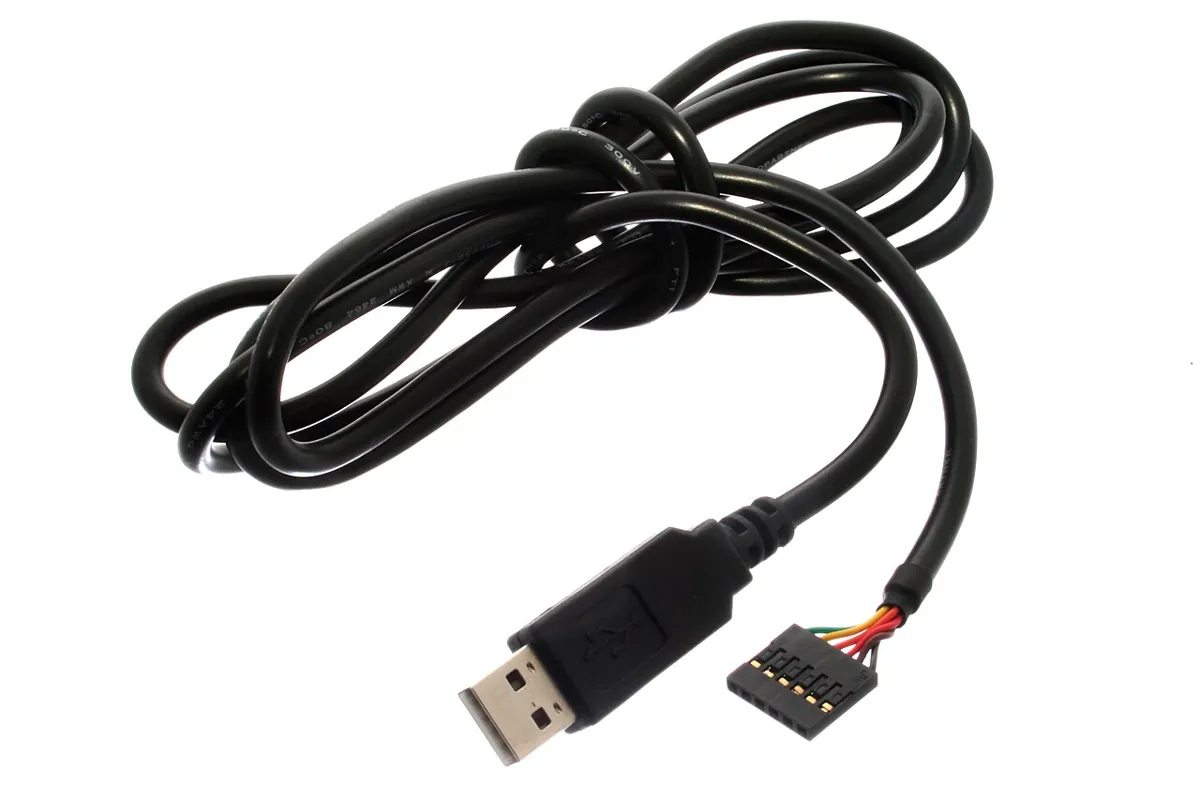
Serial works over USB.Photo: oomlout · CC BY-SA 2.0 · Source: Wikimedia Commons · resized, converted to WebPConcept
Three buses, one idea: bits in a row
UART: two wires, agreed speed
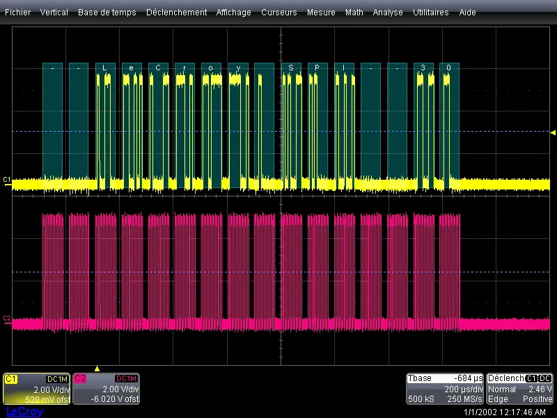
SparkFun's Serial Communication tutorial describes the asynchronous frame. The line rests at 1 (idle). A start bit (0) says “here comes a byte”. Then the data bits, least significant bit first. Then one or more stop bits back at 1. There's no clock wire, so both sides must agree on the speed — the baud rate. “9600 8N1” means 9600 bits per second, 8 data bits, no parity, 1 stop bit — 10 bits on the wire for every byte.
bit time = 1 ÷ baud; bytes per second (8N1) = baud ÷ 10
- 9600 baud → 104 µs per bit, 960 bytes per second
- 115200 baud → 8.7 µs per bit, 11 520 bytes per second
I²C: two wires, many devices, addresses
NXP's I²C specification (UM10204) defines two lines: SDA (data) and SCL (clock). Devices pull lines low with open-drain outputs and pull-up resistors bring them high. A transfer starts with a START, then a 7-bit address plus a read/write bit; the addressed device answers with an ACK, and every following byte is acknowledged too. A STOP ends it. Standard mode runs up to 100 kbit/s, Fast-mode 400 kbit/s and Fast-mode Plus 1 Mbit/s.
On an UNO R3, Arduino's Wire guide puts SDA on A4 and SCL on A5. The Wire reference adds that the library uses a 32-byte buffer, so longer transfers must be split.
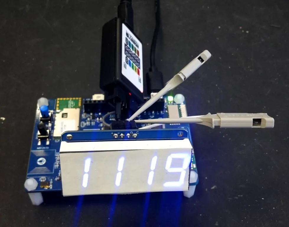
SPI: four wires, a clock, a chip select
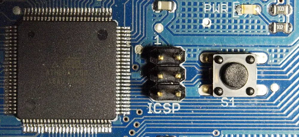
SPI (SparkFun's SPI tutorial) uses a clock (SCK), a data line from controller to peripheral (COPI/PICO), one back (CIPO/POCI), and a chip select (CS) per device. CS is active low: pull it low and that device listens; others stay off the bus. Every clock pulse moves one bit each way at the same time — SPI is full duplex. On an UNO R3 the SPI pins are 10 (CS), 11 (COPI), 12 (CIPO), 13 (SCK).
| UART | I²C | SPI | |
|---|---|---|---|
| Wires (plus GND) | 2 (TX, RX) | 2 (SDA, SCL) + pull-ups | 3 + one CS per device |
| Clock | None — agreed baud | Shared SCL | Shared SCK |
| Devices | Usually two | Many, by address | Many, by chip select |
| Typical speed | 9600–115200 baud on hobby boards | 100 / 400 kbit/s, 1 Mbit/s | Usually the fastest of the three |
| Robot examples | Bluetooth/GPS modules, PC link | IMUs, PCA9685 servo driver | SD cards, fast IMUs, displays |
Pull-ups
Sizing I²C pull-ups
UM10204 section 7.1 gives the limits. The smallest resistor is set by the current a device can sink while holding the line low: Rp(min) = (VDD − 0.4 V) ÷ 3 mA. The largest is set by bus capacitance: the line must rise within the mode's maximum rise time (1000 ns for Standard mode, 300 ns for Fast-mode, 120 ns for Fast-mode Plus), and rise time ≈ 0.8473 × Rp × C.
| Bus capacitance | Max Rp at 100 kbit/s | Max Rp at 400 kbit/s |
|---|---|---|
| 50 pF | 23.6 kΩ | 7.1 kΩ |
| 100 pF | 11.8 kΩ | 3.5 kΩ |
| 200 pF | 5.9 kΩ | 1.8 kΩ |
Visual
Visualise it: bus wiring in the full robot
Treat “signals only to driver / logic inputs” as bus hygiene too: SDA/SCL and SPI lines go to logic inputs at the right voltage, never to motors. Browser simulation only.
Interactive · Robot Electronics Wiring Lab
Assemble a full educational architecture: power, common ground, MCU, driver, actuators, sensors, and clean signal paths. Unlock Embedded Robot Ready.
- Missing: Dedicated low-voltage PSU for actuators
- Missing: Common ground MCU ↔ driver ↔ sensors
- Missing: MCU / embedded brain present
- Missing: Motor/servo driver between MCU and actuator
- …+3 more
Low-voltage educational sim · sims ≠ datasheets · never access real hardware from the browser.
Code lab
Code lab: draw the bits
1. UART frames bit by bit
This script draws the letter ‘A’ as a 9600 8N1 frame, compares baud rates, shows what a receiver sees at the wrong speed, and prints the crossed wiring rule.
"""uart_frames.py - draw UART (asynchronous serial) frames bit by bit (Stage 4, Lesson 13).

Pure Python simulation, no real serial port is opened. Rules from SparkFun's "Serial
Communication" tutorial: idle line is 1, one start bit (0), data least-significant bit
first, stop bit(s) back at 1; "9600 8N1" = 9600 baud, 8 data bits, no parity, 1 stop bit.
"""


def frame_8n1(byte):
    """Return the list of line levels for one 8N1 frame: start, 8 data bits LSB first, stop."""
    data = [(byte >> i) & 1 for i in range(8)]
    return [0] + data + [1]


def draw(bits):
    return "".join("\u203e" if b else "_" for b in bits)


print("1) The letter 'A' (0x41 = 0100 0001) as 9600 8N1")
bits = frame_8n1(ord("A"))
print("   bits on the wire :", " ".join(map(str, bits)))
print("   picture (idle=1) :", "\u203e\u203e" + draw(bits) + "\u203e\u203e")
print("   order            : start, b0..b7 (LSB first), stop")

print("\n2) Timing at common baud rates (10 bits per 8N1 byte)")
msg = "angle=090 dist=034\n"
for baud in (9600, 57600, 115200):
    bit_us = 1e6 / baud
    bytes_per_s = baud / 10
    msg_ms = len(msg) * 10 / baud * 1000
    print(f"   {baud:>6} baud: 1 bit = {bit_us:6.2f} us, {bytes_per_s:>6.0f} bytes/s, "
          f"{len(msg)}-byte message = {msg_ms:5.2f} ms")


def receive(line, rx_baud, tx_baud, nbytes):
    """A receiver sampling at rx_baud a line that was sent at tx_baud."""
    out = []
    t = 0.0
    tx_bit = 1.0 / tx_baud
    rx_bit = 1.0 / rx_baud
    level_at = lambda time: line[min(int(time / tx_bit), len(line) - 1)]
    while len(out) < nbytes and t < len(line) * tx_bit:
        if level_at(t) == 0:                     # falling edge = start bit
            value = 0
            for i in range(8):                   # sample mid-bit at the RECEIVER's rate
                if level_at(t + (1.5 + i) * rx_bit):
                    value |= 1 << i
            out.append(value)
            t += 10 * rx_bit
        else:
            t += tx_bit / 8
    return out


print("\n3) Baud mismatch: sender at 9600, receiver at the wrong speed")
text = "OK"
line = [1, 1]
for ch in text:
    line += frame_8n1(ord(ch)) + [1]
for rx in (9600, 19200, 4800):
    got = receive(line, rx, 9600, len(text))
    shown = "".join(chr(b) if 32 <= b < 127 else "?" for b in got)
    hexes = " ".join(f"{b:02X}" for b in got)
    print(f"   receiver {rx:>5}: bytes {hexes:<6} -> '{shown}'")

print("\n4) Wiring rule: TX goes to RX (crossed), grounds joined")
for a, b in (("Uno TX (pin 1)", "module RX"), ("Uno RX (pin 0)", "module TX"), ("Uno GND", "module GND")):
    print(f"   {a:<16} -> {b}")
Output (run with python3 uart_frames.py)
1) The letter 'A' (0x41 = 0100 0001) as 9600 8N1
   bits on the wire : 0 1 0 0 0 0 0 1 0 1
   picture (idle=1) : ‾‾_‾_____‾_‾‾‾
   order            : start, b0..b7 (LSB first), stop

2) Timing at common baud rates (10 bits per 8N1 byte)
     9600 baud: 1 bit = 104.17 us,    960 bytes/s, 19-byte message = 19.79 ms
    57600 baud: 1 bit =  17.36 us,   5760 bytes/s, 19-byte message =  3.30 ms
   115200 baud: 1 bit =   8.68 us,  11520 bytes/s, 19-byte message =  1.65 ms

3) Baud mismatch: sender at 9600, receiver at the wrong speed
   receiver  9600: bytes 4F 4B  -> 'OK'
   receiver 19200: bytes FE 98  -> '??'
   receiver  4800: bytes 6D     -> 'm'

4) Wiring rule: TX goes to RX (crossed), grounds joined
   Uno TX (pin 1)   -> module RX
   Uno RX (pin 0)   -> module TX
   Uno GND          -> module GND
2. An I²C read and an SPI exchange
This one traces reading the LSM6DS3's WHO_AM_I register over I²C (with a wrong-address try), converts 8-bit datasheet addresses, sizes pull-ups, checks the Wire buffer, and clocks the same read over SPI.
"""i2c_spi_sim.py - an I2C register read and an SPI exchange, traced step by step (Lesson 13).

Pure Python simulation. Facts used: NXP UM10204 (START/STOP, 7-bit address + R/W bit,
ACK after every byte, 100/400/1000 kbit/s modes, tr max 1000/300/120 ns, T = 0.8473 x RC,
Rp(min) = (VDD - 0.4 V) / 3 mA), ST LSM6DS3 datasheet (address 110101x, WHO_AM_I 0x0F = 0x69),
Arduino Wire reference (7-bit addresses, 32-byte buffer), SparkFun SPI tutorial (CS active low).
"""

# ---------- I2C ----------
class FakeLSM6DS3:
    def __init__(self, sa0):
        self.addr = 0x6A | sa0          # 110101 + SA0
        self.regs = {0x0F: 0x69}        # WHO_AM_I
        self.ptr = 0

    def ack_address(self, a):
        return a == self.addr


def i2c_read_register(bus, addr7, reg):
    log = ["START"]
    w = (addr7 << 1) | 0
    dev = next((d for d in bus if d.ack_address(addr7)), None)
    log.append(f"addr 0x{addr7:02X}+W = 0x{w:02X} {'ACK' if dev else 'NACK'}")
    if dev is None:
        log.append("STOP  (nobody answered: wrong address, no pull-ups or no power)")
        return None, log
    dev.ptr = reg
    log.append(f"reg 0x{reg:02X} ACK")
    log.append("repeated START")
    r = (addr7 << 1) | 1
    log.append(f"addr 0x{addr7:02X}+R = 0x{r:02X} ACK")
    val = dev.regs.get(dev.ptr, 0xFF)
    log.append(f"data 0x{val:02X} NACK (controller says: last byte)")
    log.append("STOP")
    return val, log


print("1) I2C: read WHO_AM_I from an LSM6DS3 breakout")
bus = [FakeLSM6DS3(sa0=1)]           # SparkFun breakout default 0x6B
for addr in (0x6B, 0x6A):
    val, log = i2c_read_register(bus, addr, 0x0F)
    print(f"   try 0x{addr:02X}:")
    for line in log:
        print("      " + line)
    if val is not None:
        print(f"      -> WHO_AM_I = 0x{val:02X} ({'LSM6DS3 found' if val == 0x69 else 'unknown chip'})")

print("\n2) 8-bit 'addresses' in datasheets vs 7-bit in Wire")
for eight in (0xD6, 0xD7):
    print(f"   datasheet 0x{eight:02X} -> Wire uses 0x{eight >> 1:02X} ({'write' if eight & 1 == 0 else 'read'} form)")

print("\n3) Pull-up sizing (UM10204 section 7.1)")
modes = (("Sm-100k", 1000e-9), ("Fm-400k", 300e-9), ("Fm+-1M", 120e-9))
rp_min = (5.5 - 0.4) / 0.003
print(f"   Rp(min) at 5 V +10 % = (5.5 - 0.4) / 3 mA = {rp_min / 1000:.2f} kOhm")
for cb_pf in (50, 100, 200):
    cb = cb_pf * 1e-12
    parts = []
    for name, tr in modes:
        parts.append(f"{name} {tr / (0.8473 * cb) / 1000:5.1f}k")
    print(f"   bus {cb_pf:>3} pF -> Rp(max): " + ", ".join(parts))
rise = 0.8473 * 4700 * 100e-12
print(f"   4.7 kOhm on 100 pF: rise time {rise * 1e9:.0f} ns (OK for 100 kbit/s, too slow for 400 kbit/s)")

print("\n4) Wire buffer: 32 bytes per transmission")
for n in (6, 32, 40):
    print(f"   send {n:>2} bytes -> {'fits' if n <= 32 else f'{n - 32} bytes dropped - split it up'}")

# ---------- SPI ----------
print("\n5) SPI mode 0: every clock moves one bit EACH way (full duplex)")
# LSM6DS3 SPI read: first bit sent = 1 (read), then the 7-bit register address -> 0x80 | 0x0F
tx_bytes = [0x80 | 0x0F, 0x00]   # command byte, then a dummy byte to clock the answer out
peripheral_bytes = [0x00, 0x69]  # the sensor has nothing to say during the command byte
cs = {"IMU": 1, "SD": 1}
cs["IMU"] = 0                    # active low: select only the IMU
print(f"   CS lines: IMU={cs['IMU']} (selected), SD={cs['SD']} (stays off the bus)")
for n, (tx, px) in enumerate(zip(tx_bytes, peripheral_bytes), start=1):
    rx = 0
    pico_bits, poci_bits = "", ""
    for i in range(7, -1, -1):   # most significant bit first
        pico_bits += str((tx >> i) & 1)
        bit = (px >> i) & 1
        poci_bits += str(bit)
        rx = (rx << 1) | bit
    print(f"   byte {n}: PICO {pico_bits} (0x{tx:02X})   POCI {poci_bits} (0x{rx:02X})")
print("   -> answer 0x69 arrives in byte 2: the same WHO_AM_I value as over I2C")
cs["IMU"] = 1
print("   CS back HIGH -> transaction over, bus free for the SD card")
Output (run with python3 i2c_spi_sim.py)
1) I2C: read WHO_AM_I from an LSM6DS3 breakout
   try 0x6B:
      START
      addr 0x6B+W = 0xD6 ACK
      reg 0x0F ACK
      repeated START
      addr 0x6B+R = 0xD7 ACK
      data 0x69 NACK (controller says: last byte)
      STOP
      -> WHO_AM_I = 0x69 (LSM6DS3 found)
   try 0x6A:
      START
      addr 0x6A+W = 0xD4 NACK
      STOP  (nobody answered: wrong address, no pull-ups or no power)

2) 8-bit 'addresses' in datasheets vs 7-bit in Wire
   datasheet 0xD6 -> Wire uses 0x6B (write form)
   datasheet 0xD7 -> Wire uses 0x6B (read form)

3) Pull-up sizing (UM10204 section 7.1)
   Rp(min) at 5 V +10 % = (5.5 - 0.4) / 3 mA = 1.70 kOhm
   bus  50 pF -> Rp(max): Sm-100k  23.6k, Fm-400k   7.1k, Fm+-1M   2.8k
   bus 100 pF -> Rp(max): Sm-100k  11.8k, Fm-400k   3.5k, Fm+-1M   1.4k
   bus 200 pF -> Rp(max): Sm-100k   5.9k, Fm-400k   1.8k, Fm+-1M   0.7k
   4.7 kOhm on 100 pF: rise time 398 ns (OK for 100 kbit/s, too slow for 400 kbit/s)

4) Wire buffer: 32 bytes per transmission
   send  6 bytes -> fits
   send 32 bytes -> fits
   send 40 bytes -> 8 bytes dropped - split it up

5) SPI mode 0: every clock moves one bit EACH way (full duplex)
   CS lines: IMU=0 (selected), SD=1 (stays off the bus)
   byte 1: PICO 10001111 (0x8F)   POCI 00000000 (0x00)
   byte 2: PICO 00000000 (0x00)   POCI 01101001 (0x69)
   -> answer 0x69 arrives in byte 2: the same WHO_AM_I value as over I2C
CS back HIGH -> transaction over, bus free for the SD cardReal world
Where these buses run in real robots
- Servo drivers: Adafruit's PCA9685 board takes 16 servo channels over I²C at default address 0x40 — two wires instead of sixteen.
- Drones and arms: IMUs read over I²C or SPI hundreds of times a second.
- Telemetry: robots stream status lines over UART/USB to a laptop or companion computer.
- Data logging: SD cards on SPI store sensor logs.
Bench build
Bench build: say hello to an IMU
Wire with USB unplugged
SDA to A4, SCL to A5, GND to GND, power as the breakout's guide says.
Upload
Open the Serial Monitor at 115200 baud.
Read the answer
WHO_AM_I = 0x69 means an LSM6DS3 answered. No ACK? Try 0x6A, check power and pull-ups.
// i2c_whoami.ino — find a device on the I2C bus and read its ID register (Stage 4, Lesson 13).
// For a REAL board on your bench. This sketch is not run inside the browser.
//
// WIRING (Arduino UNO R3)
//   Sensor breakout SDA -> A4, SCL -> A5, GND -> GND, power -> the voltage the BOARD's guide says.
//   The LSM6DS3 chip is a 3.3 V part: use a breakout with a regulator/level shifting, or a 3.3 V board.
//   I2C needs pull-up resistors on SDA and SCL - most breakouts already have them.
// SAFETY: low power; still unplug USB before rewiring.

#include <Wire.h>

const byte ADDR = 0x6B;        // 7-bit address (0x6A if the SA0/SDO pin is tied low)
const byte WHO_AM_I = 0x0F;    // datasheet register; an LSM6DS3 answers 0x69

void setup() {
  Serial.begin(115200);
  Wire.begin();                                   // UNO becomes the controller

  Wire.beginTransmission(ADDR);
  Wire.write(WHO_AM_I);                           // which register we want
  byte err = Wire.endTransmission(false);         // false = repeated START, keep the bus
  if (err != 0) {
    Serial.print(F("No ACK from 0x")); Serial.println(ADDR, HEX);
    Serial.println(F("Check address, power, pull-ups, SDA/SCL swapped?"));
    return;
  }
  Wire.requestFrom(ADDR, (byte)1);
  if (Wire.available()) {
    byte id = Wire.read();
    Serial.print(F("WHO_AM_I = 0x")); Serial.println(id, HEX);
  }
}

void loop() {}Debugging
Debugging a silent bus
| Symptom | Likely cause | Fix |
|---|---|---|
| Random symbols in the monitor | Baud mismatch | Same baud on both sides |
| UART module says nothing | TX wired to TX | Cross them: TX → RX |
| I²C device not found | Wrong address (8-bit form), no power, no pull-ups, SDA/SCL swapped | Use the 7-bit address; check power and pull-ups with a meter |
| Two I²C devices fight | Same address | Change one with its address pin or jumper |
| I²C works short, fails with long wires | Too much capacitance, slow rise | Shorter wires, lower speed, stronger pull-ups within Rp(min) |
| SPI device answers garbage | Wrong SPI mode or CS not low | Check the datasheet mode; one CS low at a time |
Think
Think about it
Think
Arjun's datasheet says the IMU address is 0xD6. His sketch uses `Wire.beginTransmission(0xD6)` and gets no ACK. Why, and what should he write?
Experiment
Try it in the lab: decode the bus
Use the scripts and paper to decode frames like a logic analyser would.
Experiment
Decode the bus
You will need
- Robot wiring lab (in your browser)
- Notebook
- Optional: `uart_frames.py` and `i2c_spi_sim.py`
Steps
- Draw the 9600 8N1 frame for ‘O’ (0x4F). Count the bits.
- How long does a 19-byte message take at 9600 and at 115200 baud?
- Write the I²C sequence to read register 0x0F from address 0x6A.
- List which SPI CS lines are high and low while reading the IMU with an SD card on the bus.
- In the wiring lab, reach Embedded Robot Ready and note which check covers bus wiring.
Interactive · Robot Electronics Wiring Lab
Assemble a full educational architecture: power, common ground, MCU, driver, actuators, sensors, and clean signal paths. Unlock Embedded Robot Ready.
- Missing: Dedicated low-voltage PSU for actuators
- Missing: Common ground MCU ↔ driver ↔ sensors
- Missing: MCU / embedded brain present
- Missing: Motor/servo driver between MCU and actuator
- …+3 more
Low-voltage educational sim · sims ≠ datasheets · never access real hardware from the browser.
Every bus is just agreed rules about when a bit is valid: UART by time, I²C and SPI by a clock — and I²C and SPI pick devices by address or chip select.
Knowledge check
Check your understanding
Knowledge check
1. In 9600 8N1, how many bits travel per byte?
2. UNO TX should connect to the module's…
3. Garbage characters usually mean…
4. On an UNO R3, I²C is on…
5. Why does I²C need pull-up resistors?
6. After each byte on I²C, the receiver sends…
7. Fast-mode I²C runs up to…
8. What does an SPI chip select do when pulled LOW?
9. SPI is full duplex. That means…
10. Wire's buffer holds 32 bytes. You need to send 40. You should…
Mini assignment
Hands-on assignment
Mini assignment
Bus map for your robot
Plan every data connection of your robot: which bus, which pins, which address or CS, which speed.
Deliverables
- A bus table: device, bus, pins, address or CS pin, logic level, speed — with datasheet links.
- A check that no two I²C devices share an address, and pull-up values within Rp(min) and Rp(max).
- The UART wiring for one module, drawn with crossed TX/RX and common ground.
- One frame you drew by hand, checked with `uart_frames.py`.
- Output of `i2c_spi_sim.py` with one change of your own and a sentence on what it shows.
Do this, step by step
- List every data connection on your robot and pick the bus for each (UART, I²C or SPI).
- Fill the bus table: device, bus, pins, address or CS, logic level, speed — with datasheet links.
- Check no two I²C devices share an address and your pull-up value is within Rp(min)–Rp(max).
- Draw one UART link with TX → RX crossed and common ground.
- Draw one UART frame by hand, check it with
uart_frames.py, and runi2c_spi_sim.pywith one change.
Stuck? Hints, one at a time
- Hint 1: UART: board TX goes to module RX and board RX to module TX — and the grounds must be joined.
- Hint 2: Two identical I²C sensors usually clash; many have an address pin (often labelled SA0 or AD0) to pick a second address.
- Hint 3: A typical I²C pull-up is 4.7 kΩ at 100 kHz; most breakout boards already have pull-ups, so check before adding more.
- Hint 4: One 8N1 UART frame is 10 bits (start + 8 data + stop), so 9600 baud ≈ 960 bytes per second.
Challenges (pick by level)
- 🟢 Easy: How many bytes per second at 57 600 baud 8N1?
- 🟢 Easy: Convert 8-bit addresses 0x80 and 0x81 to 7-bit.
- 🟡 Medium: Two PCA9685 boards on one bus — what addresses would you give them? *Hint:* Adafruit's address jumpers add to 0x40.
- 🟠 Hard-ish: Write an I²C scanner that tries every address from 0x08 to 0x77.
- 🔴 Hard: Read the LSM6DS3 accelerometer output registers over I²C and print g on all three axes.
- ⚫ Expert: Find an SPI device's mode (clock polarity and phase) in its datasheet and explain it with a timing drawing.
Next step
You now have sensors, actuators and buses. In Lesson 14 — Embedded Robot Architecture you'll put them into layers — power, compute, drivers, actuators, sensors, communication and safety — and design a whole robot's electrical system on one page.
Look back: Lesson 12: Sensors & Actuators at Electrical Level. Next: Lesson 14: Embedded Robot Architecture. Related: Stage 0 — Power & Communication, Stage 3 — SSH & Remote Robotics and later Stage 10 — ROS 2.
Sources
- SparkFun: Serial Communication — frames, start/stop bits, LSB first, 8N1, crossed TX/RX.
- NXP UM10204 I²C-bus specification — open-drain, START/STOP, 7-bit address + R/W, ACK, speed modes, pull-up sizing (NXP’s old PDF link now returns 404; search “UM10204” on nxp.com for the current copy).
- TI SLVA689 — I²C bus pull-up resistor calculation — Rp(min) from the sink current, Rp(max) from rise time and bus capacitance.
- TI SLVA704 — Understanding the I²C bus — open-drain lines, addressing, START/STOP and ACK.
- SparkFun: I²C and Serial Peripheral Interface (SPI) — active-low CS, full duplex.
- Arduino: Wire guide, Wire reference — A4/A5 on UNO R3, 32-byte buffer.
- Arduino: SPI guide and SPI reference — pins 10–13 on UNO.
- Arduino reference: Serial — TTL levels vs RS-232.
- ST LSM6DS3 datasheet (SparkFun-hosted copy) — address 110101x, WHO_AM_I register 0x0F.
- Adafruit PCA9685: chaining drivers — default address 0x40.
- Photos: Wikimedia Commons (credits under each image).
Self-attested for now — keep artifacts in your lab notebook.
Complete
Today's goal
0 of 1 done today
Mark this lesson complete when you have worked the experiment, knowledge check, and assignment (even roughly).