
Electronics & Embedded Systems · Lesson 01
Why Electronics Matters in Robotics
Est. 30–40 min
Why
Why code alone can never move a robot
In Stages 2 and 3 you learned to write Python and run it on a Linux machine. That code can calculate a perfect joint angle — but an angle in a variable moves nothing. Somewhere, a few milliamps of signal from a tiny chip must be turned into the hundreds of milliamps (or more) that a motor needs, from the right battery, through the right wires, with a shared reference so everyone “understands” the signal. That bridge is robot electronics.
Here is the honest truth from every robotics lab: most first-day robot failures are not fancy algorithm bugs. They are a loose ground wire, a motor connected straight to a microcontroller pin, the wrong battery, or a sensor running at the wrong voltage. Learn this layer well and you will save hours of confused debugging — and a few burnt boards.
By the end of this chapter you will be able to name the six blocks of a robot’s electronics, trace one command from Python all the way to a moving servo, spot the classic “GPIO straight to motor” mistake, and assemble a safe stack in the browser wiring lab.
Concept
The big idea: six blocks every robot is built from
However big or small the robot — a line follower, a 6-DOF arm or a mobile base — its electronics can be drawn as six blocks. Learn these six names and every wiring diagram you see from now on becomes readable.
| Block | Home analogy | What it does in a robot |
|---|---|---|
| Power supply | Mains supply + inverter | Gives energy: a battery or adapter for motors, and a steady low voltage (often 5 V or 3.3 V) for the logic chips |
| Ground (GND) | The common floor everyone stands on | The shared 0 V reference. A signal is only “high” or “low” compared with ground |
| Brain (MCU) | The person pressing switches | A microcontroller (e.g. an Arduino-style board or ESP32) runs firmware, reads sensors and sends small control signals |
| Motor driver | The fan regulator / relay box | Takes a weak signal from the MCU and switches a strong current from the motor supply |
| Actuator | The ceiling fan | DC motor, servo or stepper that actually moves the robot |
| Sensor | Your eyes checking the fan is on | Measures angle, distance, light or current and reports back to the MCU |
Two kinds of electricity in the same robot
- Logic (signal) side: small voltages and very small currents. It carries *information* — “turn on”, “go to 30°”, “distance is 42 cm”. The MCU, sensors and the signal pins of the driver live here.
- Power side: larger currents from a battery or adapter. It carries *energy* to motors. Motors, the driver’s power pins and the battery live here.
- The driver is the gate between the two. Information goes in on the logic side; energy comes out on the power side.
- Ground ties them together. The two sides can use different supplies, but their grounds are connected so the signal has a common reference (you will see this again in Lesson 3).
Where Stage 4 sits in your journey
| Stage | Layer | Question it answers |
|---|---|---|
| Stage 2 — Python | Decisions | What should the robot do? |
| Stage 3 — Linux | Workshop / computer | Where does my code run and how do I reach the robot? |
| Stage 4 — Electronics (you are here) | Body wiring | How does a decision become safe current in a motor? |
| Stage 5+ — middleware, ROS 2, control | Coordination | How do many programs and sensors work together? |
How it works
How it actually works: one command, from Python to a moving servo
Let us follow a single command — “tilt the camera to 30 degrees” — through a typical small robot where a laptop or Raspberry Pi talks to a microcontroller over USB.
Python decides
Your script on the laptop / Pi calculates that the camera servo should go to 30°.
Serial message
It sends a short text like
TILT 30over the USB serial cable (you met/dev/ttyACM0in Stage 3).MCU firmware translates
The microcontroller reads the message and turns “30°” into a PWM signal — a repeating pulse whose width encodes the angle (Lesson 9).
Driver adds muscle
The servo’s built-in electronics or a separate driver board uses the pulse as an instruction and pulls the real current from the motor battery, not from the MCU pin.
Actuator moves
The servo motor turns to roughly 30°.
Sensor closes the loop
An angle sensor (or the servo’s own feedback, or a camera) tells the system what actually happened, so the code can correct it.
Visual
Visualise it: assemble a safe robot electronics stack
Tick the blocks to assemble a safe educational robot stack: power, common ground, MCU, driver, actuator, sensor and clean signal paths. Try ticking the hazard to see what an inspector would say. Browser simulation only.
Interactive · Robot Electronics Wiring Lab
Assemble a full educational architecture: power, common ground, MCU, driver, actuators, sensors, and clean signal paths. Unlock Embedded Robot Ready.
- Missing: Dedicated low-voltage PSU for actuators
- Missing: Common ground MCU ↔ driver ↔ sensors
- Missing: MCU / embedded brain present
- Missing: Motor/servo driver between MCU and actuator
- …+3 more
Low-voltage educational sim · sims ≠ datasheets · never access real hardware from the browser.
Worked example
Worked example: Rohan’s arm that “did nothing”
Rohan, a second-year student in Pune, builds his first 2-joint arm for the college tech fest. His Python code prints Moving to 45° perfectly, the MCU’s LED blinks — but the arm just sits there, and once the board even resets by itself. Let us debug it like a lab senior would, block by block.
| Block | What Rohan had | Problem | Fix |
|---|---|---|---|
| Power supply | Motors powered from the board’s 5 V pin via USB | Motors draw far more current than a USB port / logic regulator is meant to give; voltage dips and the MCU resets | Separate battery or adapter for motors |
| Driver | None — motor wire straight on a GPIO pin | A GPIO pin can only give a few tens of milliamps; the motor needs much more, and its electrical kick can damage the pin | Put a motor driver between GPIO and motor |
| Ground | Motor battery ground left floating | Driver and MCU have no common reference, so “high” and “low” mean nothing to the driver | Join all grounds at one common point |
| Sensor | Not connected yet | Code has no idea whether the arm moved | Add a simple angle sensor later (Lesson 12) |
Code lab
Code lab: map the stack and inspect a wiring plan in Python
You do not need any hardware for this. These two scripts only print — they are a way to make the six blocks and the safety rules concrete. Copy them into a file on your Linux laptop (from Stage 3) and run them with python3.
1. Print the robot electronics stack map
# stack_map.py — "Who does what?" map of a small robot's electronics (Stage 4, Lesson 1)
# Pure Python, no hardware needed. It only prints; it never touches a real port or pin.

STACK = [
    # (block,          job in one line,                                   everyday analogy)
    ("Power supply",  "Gives energy: a battery or adapter for motors, a clean 5 V / 3.3 V for logic", "Mains + inverter at home"),
    ("Ground (GND)",  "The shared 0 V reference every signal is measured against",               "The common floor everyone stands on"),
    ("Brain (MCU)",   "Runs firmware, reads sensors, sends tiny control signals",                 "The person pressing switches"),
    ("Motor driver",  "Turns a tiny signal into a big, safe current for the motor",               "The fan regulator / relay box"),
    ("Actuator",      "Motor or servo that actually moves the arm",                               "The ceiling fan itself"),
    ("Sensor",        "Measures the world (angle, distance, current) and reports back",           "Your eyes checking the fan is on"),
]

print("ROBOT ELECTRONICS STACK MAP")
print("=" * 60)
for number, (block, job, analogy) in enumerate(STACK, start=1):
    print(f"{number}. {block:<13}| {job}")
    print(f"   {'':<13}| like: {analogy}")
print("=" * 60)

# Follow ONE command from Python all the way to the motor and back.
command_path = [
    "Python on laptop     : decide 'tilt camera to 30 degrees'",
    "USB serial cable     : send the text 'TILT 30' to the MCU",
    "MCU firmware         : turn 30 degrees into a PWM pulse",
    "Driver / servo board : amplify the pulse using the motor battery",
    "Servo motor          : rotate to about 30 degrees",
    "Sensor               : report the angle actually reached",
]
print("One command, start to finish:")
for step, text in enumerate(command_path, start=1):
    print(f"  step {step} -> {text}")
print(f"Blocks in the stack: {len(STACK)} | hops for one command: {len(command_path)}")
Output (run with python3 stack_map.py)
ROBOT ELECTRONICS STACK MAP
============================================================
1. Power supply | Gives energy: a battery or adapter for motors, a clean 5 V / 3.3 V for logic
                | like: Mains + inverter at home
2. Ground (GND) | The shared 0 V reference every signal is measured against
                | like: The common floor everyone stands on
3. Brain (MCU)  | Runs firmware, reads sensors, sends tiny control signals
                | like: The person pressing switches
4. Motor driver | Turns a tiny signal into a big, safe current for the motor
                | like: The fan regulator / relay box
5. Actuator     | Motor or servo that actually moves the arm
                | like: The ceiling fan itself
6. Sensor       | Measures the world (angle, distance, current) and reports back
                | like: Your eyes checking the fan is on
============================================================
One command, start to finish:
  step 1 -> Python on laptop     : decide 'tilt camera to 30 degrees'
  step 2 -> USB serial cable     : send the text 'TILT 30' to the MCU
  step 3 -> MCU firmware         : turn 30 degrees into a PWM pulse
  step 4 -> Driver / servo board : amplify the pulse using the motor battery
  step 5 -> Servo motor          : rotate to about 30 degrees
  step 6 -> Sensor               : report the angle actually reached
Blocks in the stack: 6 | hops for one command: 62. A tiny wiring safety inspector
Now we describe a wiring plan as a list of (from, to) pairs and check it with four simple rules: no GPIO-to-motor, signal goes to the driver, driver has a motor supply, and every board shares one ground. This is the same thinking the wiring lab above uses.
# wiring_check.py — a tiny "safety inspector" for a robot wiring plan (Stage 4, Lesson 1)
# Simulation only: we describe the wiring as Python data and check it with simple rules.

def check_wiring(name, wires):
    """wires is a list of (from_block, to_block) pairs. Returns a list of problems."""
    problems = []
    connected = set(wires)

    # Rule 1: a GPIO pin must never drive a motor directly — use a driver.
    if ("MCU GPIO", "Motor") in connected:
        problems.append("GPIO wired straight to motor -> add a motor driver in between")

    # Rule 2: the MCU must send its signal to the driver, not skip it.
    if ("MCU GPIO", "Driver IN") not in connected:
        problems.append("No signal wire from MCU GPIO to Driver IN")

    # Rule 3: motor power must come from the motor supply through the driver.
    if ("Motor PSU", "Driver VM") not in connected:
        problems.append("Driver has no motor supply (Motor PSU -> Driver VM)")

    # Rule 4: every board must share one ground, or signals mean nothing.
    for board in ("MCU GND", "Driver GND", "Sensor GND"):
        if (board, "Common GND") not in connected:
            problems.append(f"{board} is not tied to Common GND")

    print(f"--- {name} ---")
    if problems:
        for p in problems:
            print("  PROBLEM:", p)
        print(f"  Result : NOT READY ({len(problems)} problem(s))")
    else:
        print("  Result : READY - power, ground, signal and driver look sane (sim)")
    return problems


first_try = [
    ("MCU GPIO", "Motor"),          # the classic beginner shortcut
    ("MCU GND", "Common GND"),
    ("Sensor GND", "Common GND"),
]

fixed_plan = [
    ("MCU GPIO", "Driver IN"),      # small signal goes to the driver
    ("Motor PSU", "Driver VM"),     # big current comes from the motor supply
    ("Driver OUT", "Motor"),        # driver feeds the motor
    ("MCU GND", "Common GND"),
    ("Driver GND", "Common GND"),
    ("Sensor GND", "Common GND"),
]

check_wiring("First try", first_try)
check_wiring("Fixed plan", fixed_plan)
Output (run with python3 wiring_check.py)
--- First try ---
  PROBLEM: GPIO wired straight to motor -> add a motor driver in between
  PROBLEM: No signal wire from MCU GPIO to Driver IN
  PROBLEM: Driver has no motor supply (Motor PSU -> Driver VM)
  PROBLEM: Driver GND is not tied to Common GND
  Result : NOT READY (4 problem(s))
--- Fixed plan ---
  Result : READY - power, ground, signal and driver look sane (sim)
Real world
Where this shows up in a real robot lab
- College robotics clubs and tech-fest teams: a large share of “robot not working” moments on competition day turn out to be loose wires, flat batteries or a missing ground — not code.
- Robot arms: each joint motor or servo has a driver; the brain only sends position commands.
- Mobile robots and rovers: a battery feeds a motor driver for the wheels, while a regulator gives a clean low voltage to the MCU and sensors.
- Jetson / Raspberry Pi + MCU stacks: the Linux board does vision and planning; a microcontroller handles PWM and sensor reading in real time over a serial link.
- Factory and warehouse robots: use the same idea at bigger scale — industrial drives, emergency-stop circuits and fuses between the controller and the motors.
Mistakes
Common mistakes and confusions
Hardware & safety
Hardware lab and safety notes
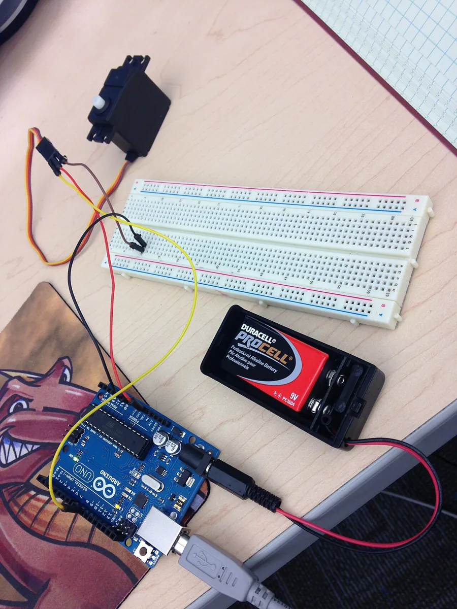
You can try this lesson’s idea on a real desk with a starter kit — but only the safe, low-power part. The goal is to *see* the six blocks, not to drive a motor yet.
- Lay out an Arduino Uno (or any board), a USB cable, a small servo, a 4×AA battery holder and a breadboard. Put a paper label on each: Brain, Power, Ground, Actuator…
- Trace with your finger: USB → board (logic power), battery → servo red wire (actuator power), battery − → board GND (common ground), board pin 9 → servo signal wire (information only).
- Do not connect the battery yet — this is a “dry run” layout. You will wire and power servos properly in Lessons 3 and 9.
Debugging
Debugging: when it doesn’t work
| Symptom | Likely cause | Fix |
|---|---|---|
| Board resets when the motor or servo starts | Motor is powered from the board’s 5 V / USB | Give motors their own supply; join grounds |
| Motor does nothing, pin LED blinks | Motor wired straight to a GPIO pin (no driver) | Put a driver (MOSFET / motor driver) between pin and motor |
| Driver ignores the signal | No common ground between MCU and motor supply | Join MCU GND, driver GND and battery − at one point |
wiring_check.py prints NOT READY | One rule still failing | Read the first problem line, fix that wire in the plan, run again |
Think
Think about it
Think
Your Python code is perfect and the MCU is happily blinking its LED — but the motor driver is missing and the motor is wired straight to a GPIO pin. What happens when you run the code?
Experiment
Try it in the lab: the “Embedded Robot Ready” challenge
Ten to fifteen minutes, notebook open. You will build a safe stack in the browser wiring lab and explain each choice — exactly what a lab senior would ask you at the bench.
Experiment
The “Embedded Robot Ready” challenge
You will need
- Robot Electronics Wiring Lab (below, runs in your browser)
- Notebook or a text file
- Optional: your Linux laptop to run `wiring_check.py`
Steps
- Open the wiring lab below. Read all eight options before ticking anything.
- First, tick **only** “GPIO wired straight to motor (unsafe)”. Note the warning the lab shows.
- Untick the hazard. Now tick the blocks one by one in this order: PSU → common ground → MCU → driver → actuator → sensor → signal paths.
- After each tick, read the “Not ready yet” list and write down which item disappeared.
- When you see **✓ Embedded Robot Ready**, take a screenshot or write down the final list.
- Untick “Common ground” and watch the status change. Write one line on why ground matters.
- Optional: edit `fixed_plan` in `wiring_check.py` to match exactly what you ticked, and confirm it prints READY.
Interactive · Robot Electronics Wiring Lab
Assemble a full educational architecture: power, common ground, MCU, driver, actuators, sensors, and clean signal paths. Unlock Embedded Robot Ready.
- Missing: Dedicated low-voltage PSU for actuators
- Missing: Common ground MCU ↔ driver ↔ sensors
- Missing: MCU / embedded brain present
- Missing: Motor/servo driver between MCU and actuator
- …+3 more
Low-voltage educational sim · sims ≠ datasheets · never access real hardware from the browser.
The lab only says Ready when every required block is present and the hazard is removed. That mirrors real life: one dangerous wire is enough to fail a design, even if everything else is perfect.
Knowledge check
Check your understanding
Knowledge check
1. Robot electronics mainly connects…
2. The interactives in this stage…
3. Which journey order makes most sense?
4. Why do we put a motor driver between the MCU and a motor?
5. Motors run from their own battery and the MCU from USB. What else must you do so the driver understands the MCU’s signal?
Mini assignment
Hands-on assignment
Mini assignment
Electronics why-card + GPIO don’t-list
Make a one-page card for your robot path that explains, in your own words, why electronics matters and what must never hang off a bare GPIO pin.
Deliverables
- Five bullets: why electronics matters for the robot you want to build
- A six-block sketch (power, ground, MCU, driver, actuator, sensor) with arrows showing signal vs power paths
- A “GPIO don’t-list” with at least three items (e.g. motors, solenoids, high-current LED strips)
- Screenshot or written list of your “Embedded Robot Ready” result from the wiring lab
- Output of `wiring_check.py` after you changed the plan in one small way (and one line explaining the result)
Do this, step by step
- Open the wiring lab and reach ✓ Embedded Robot Ready. Screenshot it.
- Draw the six blocks on paper for a robot you want to build. Use a solid arrow for power and a dashed arrow for signal.
- Write your GPIO don’t-list: at least three loads that must never hang off a pin, each with one line on why.
- Change one wire in
fixed_planinsidewiring_check.py(for example remove the driver ground), run it, and copy the output. - Write five “why electronics matters” bullets using the ceiling-fan story.
Stuck? Hints, one at a time
- Hint 1: The six blocks are power, ground, MCU, driver, actuator, sensor — every arrow on your sketch should start and end at one of them.
- Hint 2: For the don’t-list, think “anything with a coil or that gets warm”: motors, servos, solenoids, relays, LED strips, pumps.
- Hint 3: An Uno pin is comfortable at about 20 mA and its absolute maximum is 40 mA; a small servo can stall at 500 mA or more — that gap is your “why”.
- Hint 4: If
wiring_check.pystill says READY after your change, you removed a wire that no rule checks — try removing("Driver GND", "Common GND").
Tip: explain it as if teaching a younger cousin using the ceiling-fan story. If you can make the fan analogy match all six blocks, you have understood this chapter.
Challenges (pick by level)
- 🟢 Easy: Add a seventh block, fuse, to
stack_map.pyand explain where it sits (hint: between battery and everything else). - 🟡 Medium: Re-draw the six blocks for a line-follower robot with two DC motors. Which blocks double?
- 🟠 Hard: Add a fifth rule to
wiring_check.py: flag any plan where a sensor is powered from the motor battery. Make one plan that triggers it.
Next step
Look back: Stage 3 — Linux & Dev Environment. Next: Lesson 2: Voltage, Current & Resistance. Related: Stage 0 — Power & Communication, Stage 3 — SSH & Remote Robotics and later Stage 5 — Robotics Fundamentals.
Sources
Self-attested for now — keep artifacts in your lab notebook.
Complete
Today's goal
0 of 1 done today
Mark this lesson complete when you have worked the experiment, knowledge check, and assignment (even roughly).