
Electronics & Embedded Systems · Lesson 12
Sensors & Actuators at Electrical Level
Est. 45–60 min
Why
Why the wire matters before the code
Every lesson in this stage built one layer: voltage, circuits, components, capacitors, switches, GPIO, ADC, PWM, microcontrollers and firmware. Now we connect real parts to those pins. A sensor turns something in the world (distance, tilt, light, position) into a voltage, a pulse or bus data. An actuator turns electrical energy into motion — and it usually needs far more current than a microcontroller pin can supply. In between sit level shifting, drivers and separate supplies.
By the end you will be able to: classify a part as sensor or actuator by the direction of energy flow; read an analog, digital-pulse or bus sensor correctly; convert an HC-SR04 echo time and an IMU's raw counts into real units; protect a 3.3 V input from a 5 V signal; explain why servos, DC motors and steppers need drivers and their own supply; set a stepper driver's current limit; and use feedback to detect a stall.
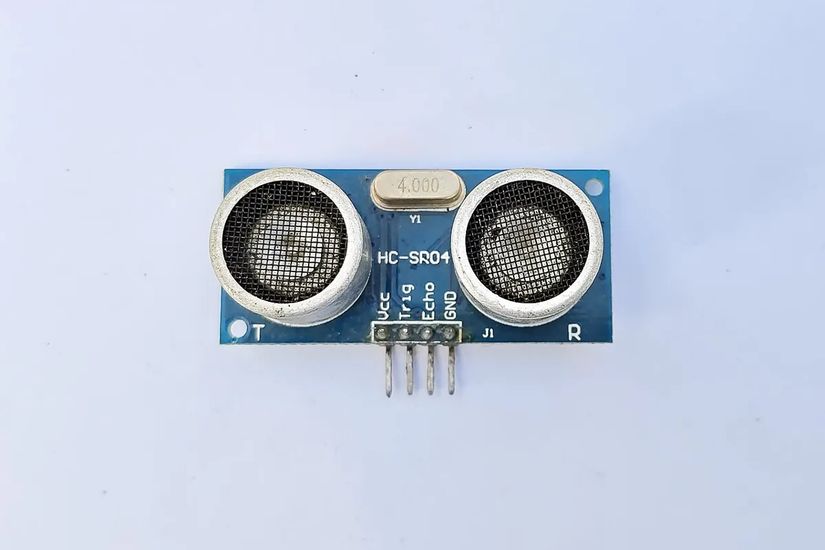
Concept
Sensors give signals, actuators take power
Here is a simple test: which way does the energy flow? A sensor takes a tiny bit of power and sends information *into* the microcontroller. An actuator takes information *from* the microcontroller but pulls its real energy from a power supply, through a driver. If a part needs hundreds of milliamps, it is not something an I/O pin can power — the ATmega328P datasheet gives 40 mA as the absolute maximum per I/O pin, and we design to about 20 mA (Lessons 7 and 9).
Three kinds of sensor signal
| Signal type | Example | How the MCU reads it | Watch out for |
|---|---|---|---|
| Analog voltage | 10 kΩ pot, LDR divider, ADXL337 | analogRead() — 0–1023 on an UNO (Lesson 8) | Noise, reference voltage, source impedance |
| Digital pulse / timing | HC-SR04 echo, encoders | pulseIn(), interrupts, timers | Timeouts, 5 V signals into 3.3 V boards |
| Bus data | LSM6DS3 IMU over I²C or SPI | Wire / SPI libraries (Lesson 13) | Addresses, pull-ups, logic levels |
Reading the HC-SR04 properly
The HC-SR04 datasheet gives the recipe: send a 10 µs pulse on Trig; the module sends eight 40 kHz bursts and raises Echo for as long as the sound took to go and come back. Distance in cm = echo time in µs ÷ 58. It ranges from 2 cm to 400 cm, and the datasheet suggests a measurement cycle of over 60 ms so old echoes don't confuse new ones.
distance (cm) = echo high time (µs) ÷ 58
- Sound travels about 340 m/s, so one centimetre there and back takes about 58 µs
- Echo width = 0 from pulseIn() means no echo before the timeout — unknown, not ‘far’
Logic levels: 5 V signals into 3.3 V boards
SparkFun's Logic Levels tutorial explains that a 3.3 V device can be damaged by a 5 V signal on its input, and that a simple resistor divider or a level shifter fixes one-way signals. The HC-SR04 runs on 5 V, so its Echo is a 5 V pulse. On an UNO (5 V logic) that's fine. On an ESP32 or Raspberry Pi Pico (3.3 V logic) divide it down first.
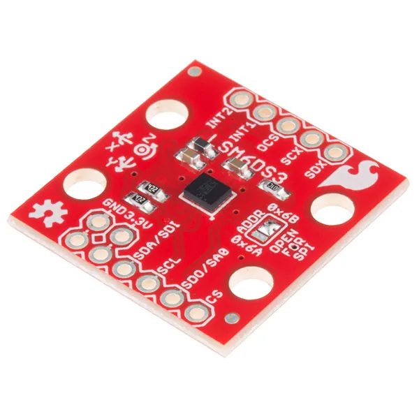
Actuators: drivers and their own supply
A hobby servo needs only a PWM *signal* from the MCU, but its motor draws its power from the red wire — feed that from a separate 5–6 V supply sized for stall current (Lesson 9). A brushed DC motor needs a MOSFET or H-bridge (Lessons 6 and 9). A stepper needs a stepper driver such as the Pololu A4988 carrier, which Pololu says runs a motor supply from 8 V to 35 V and delivers about 1 A per phase without a heat sink (rated up to 2 A per coil with enough cooling).
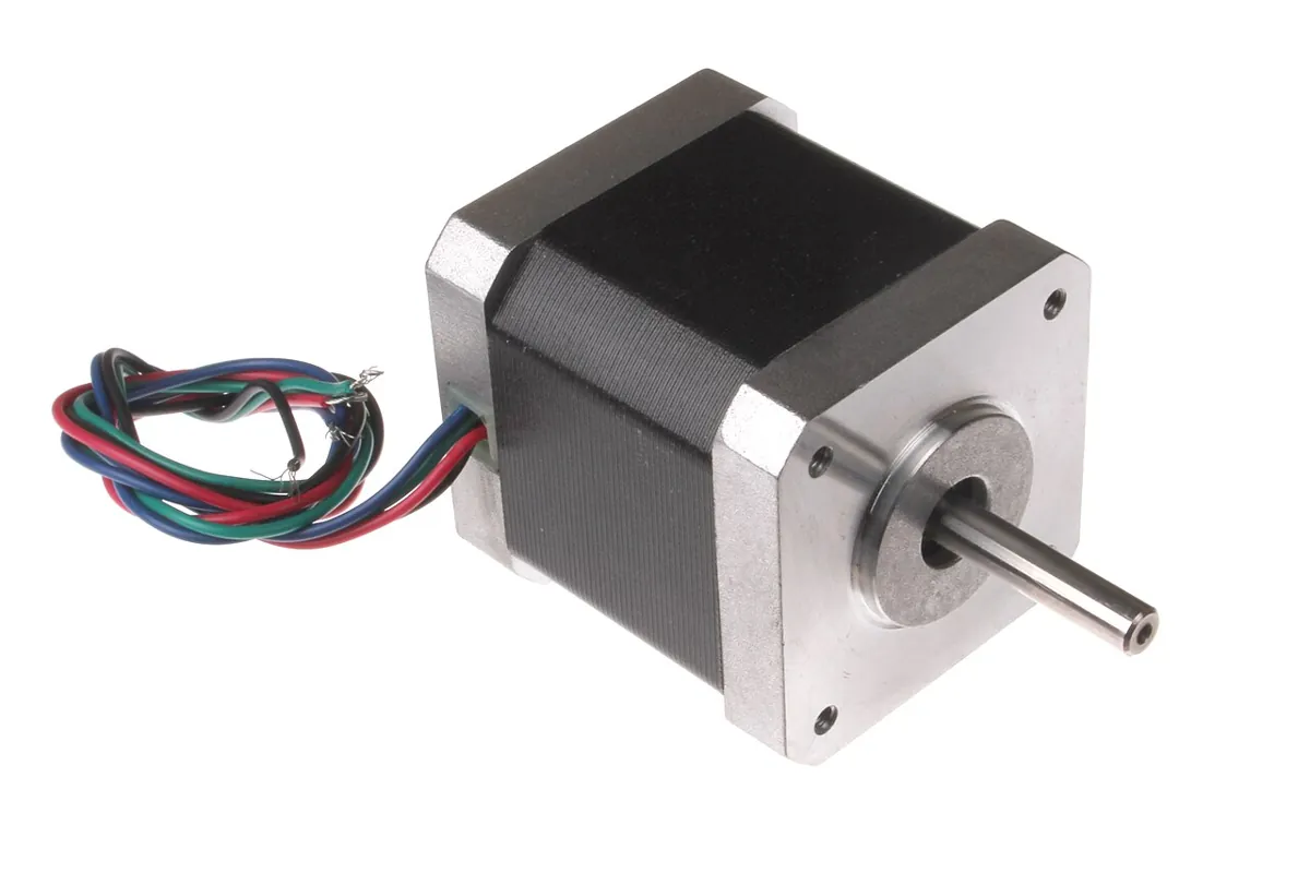
Drivers
Setting a stepper driver's current limit
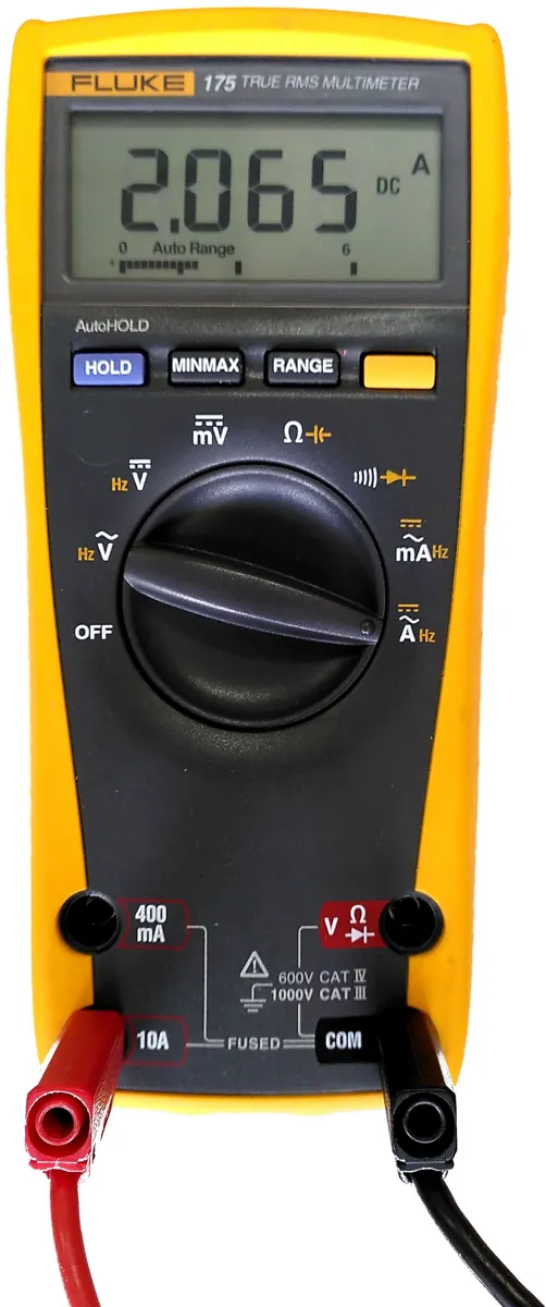
A stepper driver chops the coil current to a limit you set with a small potentiometer. Set it too high and the motor and driver overheat; too low and the motor skips steps. Pololu describes a safe way to check it: put the driver in full-step mode, hold the motor still, and measure one coil's current with a multimeter. In full-step mode the coil current is limited to about 70% of the set limit, so the meter should read 0.7 × your target.
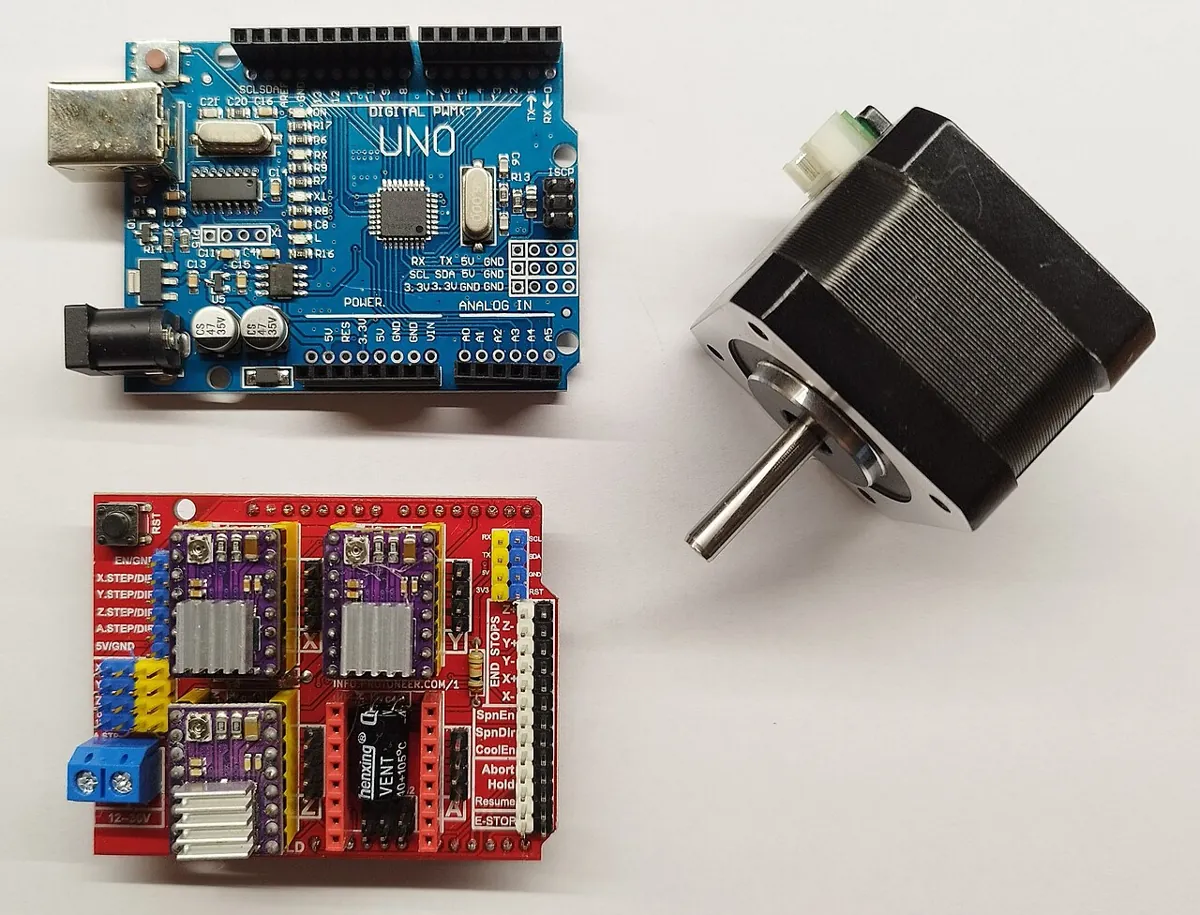
| Target per coil | Meter should read | Cooling |
|---|---|---|
| 0.6 A | 0.42 A | No heat sink needed |
| 1.0 A | 0.70 A | About Pololu's no-heat-sink limit |
| 1.5 A | 1.05 A | Needs extra cooling |
Visual
Visualise it: the full robot wiring check
Tick the blocks a real robot needs: a dedicated actuator supply, common ground, the MCU, a driver between MCU and motor, the motor on the driver's rails, a sensor on the logic rail (or level-shifted) and clean signals. Try ticking “GPIO wired straight to motor” and see the warning. Browser simulation only.
Interactive · Robot Electronics Wiring Lab
Assemble a full educational architecture: power, common ground, MCU, driver, actuators, sensors, and clean signal paths. Unlock Embedded Robot Ready.
- Missing: Dedicated low-voltage PSU for actuators
- Missing: Common ground MCU ↔ driver ↔ sensors
- Missing: MCU / embedded brain present
- Missing: Motor/servo driver between MCU and actuator
- …+3 more
Low-voltage educational sim · sims ≠ datasheets · never access real hardware from the browser.
Code lab
Code lab: signals and power budgets in Python
1. What a sensor's signal really looks like
This script turns HC-SR04 echo times into centimetres, works out how often you can range, checks a 5 V-to-3.3 V divider, and converts LSM6DS3 raw counts into g.
"""sensor_signals.py - what a sensor's signal really looks like at the wire (Stage 4, Lesson 12).

Pure Python simulation: it never touches real pins. Numbers come from the HC-SR04 datasheet
(10 us trigger, us/58 = cm, 2-400 cm, >60 ms cycle), the Arduino pulseIn() reference
(1 s default timeout) and the ST LSM6DS3 datasheet (0.061 mg/LSB at +/-2 g).
"""

SPEED_OF_SOUND = 340.0  # m/s, the value the HC-SR04 datasheet uses


def echo_us_for(distance_cm):
    """Echo pulse width (us) the module would give for an object at distance_cm."""
    return 2 * (distance_cm / 100) / SPEED_OF_SOUND * 1e6


def cm_from_echo(us):
    """The datasheet's shortcut: microseconds / 58 = centimetres."""
    return us / 58


print("1) HC-SR04: echo pulse width vs distance")
print(f"   {'object':>8} {'echo (us)':>10} {'us/58 (cm)':>11} {'340 m/s (cm)':>13}")
for d in (2, 10, 30, 100, 250, 400):
    us = echo_us_for(d)
    print(f"   {d:>6} cm {us:>10.0f} {cm_from_echo(us):>11.1f} {us * 1e-6 * SPEED_OF_SOUND / 2 * 100:>13.1f}")

print("\n2) How fast can we range?")
cycle_ms = 60  # datasheet: use over 60 ms measurement cycle
print(f"   Datasheet cycle {cycle_ms} ms -> at most {1000 / cycle_ms:.1f} readings per second")
worst_echo_ms = echo_us_for(400) / 1000
print(f"   Longest echo inside the 4 m range: {worst_echo_ms:.1f} ms")
print("   pulseIn() default timeout: 1 000 000 us = 1 s  <- loop() frozen if nothing echoes")
timeout_us = int(echo_us_for(450))
print(f"   Better: pulseIn(ECHO, HIGH, {timeout_us}) gives up after {timeout_us / 1000:.1f} ms")

print("\n3) Echo is a 5 V signal. Into a 3.3 V board? Use a divider (keep it below 3.6 V).")
v_echo = 5.0
for r_top, r_bot in ((1000, 2000), (2200, 3300), (1000, 470)):
    v_out = v_echo * r_bot / (r_top + r_bot)
    if v_out > 3.6:
        verdict = "TOO HIGH for a 3.3 V input"
    elif v_out < 0.7 * 3.3:
        verdict = "too LOW - may not read as HIGH (aim for >= 0.7 x 3.3 V)"
    else:
        verdict = "OK for a 3.3 V input"
    print(f"   {r_top:>5} ohm / {r_bot:>5} ohm -> {v_out:.2f} V  {verdict}")

print("\n4) LSM6DS3 accelerometer: raw counts -> g  (FS = +/-2 g, 0.061 mg/LSB)")
SENS_MG = 0.061
for name, raw in (("flat, Z axis", 16393), ("tilted, X axis", 8200), ("noise at rest", -35)):
    print(f"   {name:<15} raw {raw:>6} -> {raw * SENS_MG / 1000:+.3f} g")
print(f"   Full scale check: 32767 counts -> {32767 * SENS_MG / 1000:.2f} g")

print("\n5) Sense or actuate? (energy flow tells you)")
parts = [
    ("HC-SR04 ultrasonic", "sense", "15 mA working current, digital pulse out"),
    ("LSM6DS3 IMU", "sense", "1.71-3.6 V supply, I2C/SPI data"),
    ("10k pot on A0", "sense", "analog voltage 0-5 V"),
    ("Hobby servo", "actuate", "needs its own 5-6 V supply; PWM signal only from MCU"),
    ("NEMA 17 stepper", "actuate", "needs a driver (e.g. A4988) and 8-35 V motor supply"),
]
for part, kind, note in parts:
    print(f"   {part:<20} {kind:<8} {note}")
Output (run with python3 sensor_signals.py)
1) HC-SR04: echo pulse width vs distance
     object  echo (us)  us/58 (cm)  340 m/s (cm)
        2 cm        118         2.0           2.0
       10 cm        588        10.1          10.0
       30 cm       1765        30.4          30.0
      100 cm       5882       101.4         100.0
      250 cm      14706       253.5         250.0
      400 cm      23529       405.7         400.0

2) How fast can we range?
   Datasheet cycle 60 ms -> at most 16.7 readings per second
   Longest echo inside the 4 m range: 23.5 ms
   pulseIn() default timeout: 1 000 000 us = 1 s  <- loop() frozen if nothing echoes
   Better: pulseIn(ECHO, HIGH, 26470) gives up after 26.5 ms

3) Echo is a 5 V signal. Into a 3.3 V board? Use a divider (keep it below 3.6 V).
    1000 ohm /  2000 ohm -> 3.33 V  OK for a 3.3 V input
    2200 ohm /  3300 ohm -> 3.00 V  OK for a 3.3 V input
    1000 ohm /   470 ohm -> 1.60 V  too LOW - may not read as HIGH (aim for >= 0.7 x 3.3 V)

4) LSM6DS3 accelerometer: raw counts -> g  (FS = +/-2 g, 0.061 mg/LSB)
   flat, Z axis    raw  16393 -> +1.000 g
   tilted, X axis  raw   8200 -> +0.500 g
   noise at rest   raw    -35 -> -0.002 g
   Full scale check: 32767 counts -> 2.00 g

5) Sense or actuate? (energy flow tells you)
   HC-SR04 ultrasonic   sense    15 mA working current, digital pulse out
   LSM6DS3 IMU          sense    1.71-3.6 V supply, I2C/SPI data
   10k pot on A0        sense    analog voltage 0-5 V
   Hobby servo          actuate  needs its own 5-6 V supply; PWM signal only from MCU
   NEMA 17 stepper      actuate  needs a driver (e.g. A4988) and 8-35 V motor supply
2. Why actuators need drivers
This one compares each load with a GPIO pin's limits, budgets a 4-servo arm's supply, does the A4988 full-step trick, and watches commanded vs sensed angle to spot a stall.
"""actuator_power.py - why actuators need drivers and their own supply (Stage 4, Lesson 12).

Pure Python simulation. Limits used: ATmega328P 40 mA absolute maximum per I/O pin
(Lesson 7/9, Microchip datasheet) - we design to 20 mA; Pololu A4988 page: ~1 A per phase
without heat sink, 2 A per coil with extra cooling, and the full-step measurement reads
only 70 % of the current-limit setting.
"""

GPIO_DESIGN_MA = 20
GPIO_ABS_MAX_MA = 40

# Servo and motor currents below are EXAMPLE values for teaching - measure yours or read its datasheet.
loads = [
    # name, current in mA, how it is normally driven
    ("Indicator LED + 330 ohm", 9, "GPIO direct is fine"),
    ("HC-SR04 sensor (Vcc pin)", 15, "5V rail, signal pins to GPIO"),
    ("Small servo, moving", 250, "own supply; GPIO gives PWM signal only"),
    ("Small servo, stalled", 700, "own supply sized for stall"),
    ("Brushed DC gear motor", 600, "MOSFET or H-bridge driver"),
    ("Stepper coil (A4988 set 1.0 A)", 1000, "stepper driver, 8-35 V motor supply"),
]

print("1) Could a GPIO pin drive it?  (design 20 mA, absolute max 40 mA)")
for name, ma, how in loads:
    if ma <= GPIO_DESIGN_MA:
        verdict = "yes"
    elif ma <= GPIO_ABS_MAX_MA:
        verdict = "risky"
    else:
        verdict = f"NO ({ma / GPIO_ABS_MAX_MA:.0f}x abs max)"
    print(f"   {name:<32} {ma:>5} mA  {verdict:<16} -> {how}")

print("\n2) Servo supply budget for a 4-servo arm")
servos = 4
moving_ma, stall_ma = 250, 700
typical = servos * moving_ma
worst = servos * stall_ma
print(f"   All moving : {servos} x {moving_ma} mA = {typical / 1000:.1f} A")
print(f"   All stalled: {servos} x {stall_ma} mA = {worst / 1000:.1f} A")
supply = worst * 1.25
print(f"   Choose a supply >= worst x 1.25 margin = {supply / 1000:.2f} A  (e.g. a 5 V 4 A unit)")
print("   Arduino 5V pin is NOT this supply: grounds joined, power separate.")

print("\n3) A4988 current limit, full-step measurement trick")
for limit_a in (0.6, 1.0, 1.5):
    measured = 0.7 * limit_a
    cooling = "no heat sink ok" if limit_a <= 1.0 else "needs extra cooling"
    print(f"   Want {limit_a:.1f} A/coil -> meter should read {measured:.2f} A in full-step  ({cooling})")

print("\n4) Feedback: did the actuator really do it?")
commanded = [0, 30, 60, 90, 90, 90]
measured = [0, 28, 55, 61, 61, 61]   # joint jammed at ~61 degrees
for t, (c, m) in enumerate(zip(commanded, measured)):
    err = c - m
    flag = "  <-- STALL? cut power, check load" if abs(err) > 15 else ""
    print(f"   t={t * 100:>3} ms  cmd {c:>3} deg  sensed {m:>3} deg  error {err:>3}{flag}")
Output (run with python3 actuator_power.py)
1) Could a GPIO pin drive it?  (design 20 mA, absolute max 40 mA)
   Indicator LED + 330 ohm              9 mA  yes              -> GPIO direct is fine
   HC-SR04 sensor (Vcc pin)            15 mA  yes              -> 5V rail, signal pins to GPIO
   Small servo, moving                250 mA  NO (6x abs max)  -> own supply; GPIO gives PWM signal only
   Small servo, stalled               700 mA  NO (18x abs max) -> own supply sized for stall
   Brushed DC gear motor              600 mA  NO (15x abs max) -> MOSFET or H-bridge driver
   Stepper coil (A4988 set 1.0 A)    1000 mA  NO (25x abs max) -> stepper driver, 8-35 V motor supply

2) Servo supply budget for a 4-servo arm
   All moving : 4 x 250 mA = 1.0 A
   All stalled: 4 x 700 mA = 2.8 A
   Choose a supply >= worst x 1.25 margin = 3.50 A  (e.g. a 5 V 4 A unit)
   Arduino 5V pin is NOT this supply: grounds joined, power separate.

3) A4988 current limit, full-step measurement trick
   Want 0.6 A/coil -> meter should read 0.42 A in full-step  (no heat sink ok)
   Want 1.0 A/coil -> meter should read 0.70 A in full-step  (no heat sink ok)
   Want 1.5 A/coil -> meter should read 1.05 A in full-step  (needs extra cooling)

4) Feedback: did the actuator really do it?
   t=  0 ms  cmd   0 deg  sensed   0 deg  error   0
   t=100 ms  cmd  30 deg  sensed  28 deg  error   2
   t=200 ms  cmd  60 deg  sensed  55 deg  error   5
   t=300 ms  cmd  90 deg  sensed  61 deg  error  29  <-- STALL? cut power, check load
   t=400 ms  cmd  90 deg  sensed  61 deg  error  29  <-- STALL? cut power, check load
   t=500 ms  cmd  90 deg  sensed  61 deg  error  29  <-- STALL? cut power, check load
Real world
Where this shows up in real robots
- Warehouse robots and robot vacuums use range sensors and must treat “no reading” as unsafe, not as an empty path.
- Drones and balancing robots read IMUs hundreds of times a second and scale raw counts with the datasheet sensitivity.
- 3D printers and CNC machines run NEMA 17 steppers through drivers with the current limit set on each axis.
- Robot arms check commanded vs measured joint position to detect collisions and stalls, then cut power.
Bench build
Bench build: a range sensor that never freezes the loop
Wire with USB unplugged
VCC to 5V, GND to GND, Trig to pin 7, Echo to pin 8 (divider first on a 3.3 V board).
Upload and open the Serial Monitor
9600 baud. Point the sensor at a wall and check against a measuring tape.
Test the timeout
Point it at the open sky or a soft cushion. You should see “no echo” quickly — not a one-second freeze.
Measure
With a meter in series on VCC, read the module's current and compare it with the datasheet's 15 mA.
// safe_ranger.ino — HC-SR04 distance with a timeout, never a frozen loop (Stage 4, Lesson 12).
// For a REAL board on your bench. This sketch is not run inside the browser.
//
// WIRING (Arduino UNO, 5 V logic)
//   HC-SR04 VCC -> 5V, GND -> GND, TRIG -> pin 7, ECHO -> pin 8
//   On a 3.3 V board (ESP32, Pico...): ECHO is a 5 V signal - put a divider
//   (1 kOhm from ECHO, 2 kOhm to GND, take the middle) before the input pin.
// SAFETY: sensors are low power, but unplug USB before rewiring.

const int TRIG = 7;
const int ECHO = 8;
const unsigned long ECHO_TIMEOUT_US = 26470;   // ~4.5 m round trip; never wait the default 1 s
unsigned long tPing = 0;

void setup() {
  pinMode(TRIG, OUTPUT);
  pinMode(ECHO, INPUT);
  digitalWrite(TRIG, LOW);
  Serial.begin(9600);
}

void loop() {
  if (millis() - tPing >= 60) {                 // datasheet: measurement cycle over 60 ms
    tPing = millis();
    digitalWrite(TRIG, HIGH);
    delayMicroseconds(10);                       // 10 us trigger pulse
    digitalWrite(TRIG, LOW);
    unsigned long us = pulseIn(ECHO, HIGH, ECHO_TIMEOUT_US);
    if (us == 0) {
      Serial.println(F("no echo"));              // treat as UNKNOWN, not as 'far away'
    } else {
      Serial.print(us / 58); Serial.println(F(" cm"));
    }
  }
  // ...other fast, non-blocking tasks here (Lesson 11)
}Debugging
Debugging sensors and actuators
| Symptom | Likely cause | Fix |
|---|---|---|
| Distance reads 0 now and then | No echo before timeout (soft or angled target, out of range) | Treat 0 as unknown; slow down or stop |
| Whole robot freezes for a second | pulseIn() with the default timeout | Pass a timeout of about 26 ms |
| Readings jump when two sensors are close | Echo from the other sensor | Ping them one at a time, ≥60 ms apart |
| IMU gives huge or meaningless numbers | Raw counts not scaled, or wrong full-scale setting | Multiply by the datasheet sensitivity for the range you set |
| Board resets when the motor starts | Motor on the logic supply (brownout) | Own supply, driver, common ground |
| Stepper hums but doesn't turn, driver hot | Current limit wrong or coils wired wrongly | Re-check coil pairs; set the limit with the full-step method |
Think
Think about it
Think
Priya's code says `if (distance < 20) stop();` and `distance = pulseIn(ECHO, HIGH) / 58;`. Find both problems that made her rover crash, and rewrite the two lines.
Experiment
Try it in the lab: sense, drive, feed back
Use the wiring lab and the two scripts to plan the electrical side of a small robot before you touch a wire.
Experiment
Sense, drive, feed back
You will need
- Robot wiring lab (in your browser)
- Notebook
- Optional: `sensor_signals.py` and `actuator_power.py` on your laptop
Steps
- In the lab, tick “GPIO wired straight to motor”. Write down the warning and why it is unsafe.
- Fix the design until the lab shows Embedded Robot Ready. List the blocks you needed.
- Run `sensor_signals.py`. How long is the echo for an object 1 m away?
- Run `actuator_power.py`. Which loads can a GPIO pin drive directly?
- Draw your robot's power: which parts sit on the logic rail, which on the actuator rail, and where the grounds meet.
Interactive · Robot Electronics Wiring Lab
Assemble a full educational architecture: power, common ground, MCU, driver, actuators, sensors, and clean signal paths. Unlock Embedded Robot Ready.
- Missing: Dedicated low-voltage PSU for actuators
- Missing: Common ground MCU ↔ driver ↔ sensors
- Missing: MCU / embedded brain present
- Missing: Motor/servo driver between MCU and actuator
- …+3 more
Low-voltage educational sim · sims ≠ datasheets · never access real hardware from the browser.
Sensors are about signals and levels; actuators are about current and drivers. A clean design keeps them apart and joins them only at the common ground and the signal wires.
Knowledge check
Check your understanding
Knowledge check
1. Which is an actuator?
2. An HC-SR04 echo is 1176 µs long. The distance is about…
3. pulseIn() returns 0. What does it mean?
4. What is pulseIn()'s default timeout?
5. You connect the HC-SR04 Echo to a 3.3 V ESP32 input. What should you add?
6. LSM6DS3 at ±2 g reads raw 16393 on Z. That's about…
7. Why can't a GPIO pin power a small servo's motor?
8. You want 1.0 A per coil on an A4988. In full-step, the meter should read about…
9. How do you measure current with a multimeter?
10. Commanded angle 90°, sensed 61° for 300 ms. Best response?
Mini assignment
Hands-on assignment
Mini assignment
Electrical plan for a sense-and-move robot
Pick one range sensor, one IMU and two actuators, and write the electrical plan before writing any code.
Deliverables
- A table of every part: sensor or actuator, signal type, logic level, supply rail and current (from its datasheet, with the link).
- Level shifting: which signals need a divider or shifter, with the resistor values and output voltage.
- A power budget for the actuator rail (moving and stall) with a 25% margin, and the supply you'd choose.
- For any stepper: the driver, its current-limit target and the full-step meter reading.
- Output of `sensor_signals.py` or `actuator_power.py` with one change of your own.
Do this, step by step
- Pick one range sensor (e.g. HC-SR04), one IMU and two actuators.
- Make the parts table: signal type, logic level, supply rail, current — with datasheet links.
- Mark every signal that needs level shifting and give the divider values and output voltage.
- Do the actuator power budget (moving and stall) with a 25% margin and choose a supply.
- Run
sensor_signals.pyoractuator_power.pywith one change and paste the output.
Stuck? Hints, one at a time
- Hint 1: The HC-SR04 Echo pin outputs 5 V — on a 3.3 V board use a divider, e.g. 1 kΩ / 2 kΩ gives about 3.3 V.
- Hint 2: Most IMU breakouts (like the LSM6DS3) talk I²C at 3.3 V — check whether your breakout has its own regulator and level shifting.
- Hint 3: Margin: multiply the total stall current by 1.25 and pick the next supply size up.
- Hint 4: For a stepper, set the driver’s current limit before connecting the motor, using the formula from your driver’s datasheet.
Challenges (pick by level)
- 🟢 Easy: Convert echoes of 290 µs and 11 600 µs to cm.
- 🟢 Easy: Classify a buzzer, a microphone, a solenoid and a thermistor as sensor or actuator.
- 🟡 Medium: Pick two resistor values from the E12 series that bring 5 V to between 2.5 V and 3.3 V.
- 🟠 Hard-ish: Add a moving-average filter to
safe_ranger.inothat ignores zeros. *Hint:* Lesson 8. - 🔴 Hard: Read the LSM6DS3 datasheet's table of sensitivities and work out the counts for 1 g at ±4 g.
- ⚫ Expert: Design a stall detector for a DC motor using a current-sense resistor and the ADC. *Hint:* V = I × R; keep the resistor's power rating in mind.
Next step
Your IMU spoke over I²C, but we haven't opened that box yet. In Lesson 13 — Serial Communication (UART, I²C, SPI) you will see how bytes really travel between chips: start bits and baud rates, addresses and ACKs, chip selects and clocks.
Look back: Lesson 11: Arduino & Embedded Programming. Next: Lesson 13: Serial Communication (UART/I2C/SPI). Related: Stage 0 — Sensors, Stage 0 — Actuators and later Stage 11 — Computer Vision.
Sources
- HC-SR04 datasheet (Elecfreaks, via SparkFun) — 15 mA, 40 Hz bursts, 2–400 cm, 10 µs trigger, µs/58 = cm, >60 ms cycle.
- Arduino reference: pulseIn() — returns 0 if no pulse within the timeout; default one second.
- ST LSM6DS3 datasheet (SparkFun-hosted copy) — 1.71–3.6 V supply, 0.061 mg/LSB at ±2 g, I²C/SPI.
- SparkFun: LSM6DS3 Breakout Hookup Guide — wiring and level shifting.
- SparkFun: Logic Levels — 3.3 V vs 5 V, dividers and level shifters.
- Pololu A4988 Stepper Motor Driver Carrier — 8–35 V, ≥47 µF VMOT capacitor, ~1 A per phase without heat sink, 2 A with cooling, full-step 70% current-limit method, don't hot-plug motors.
- SparkFun: Motors and Selecting the Right One and Easy Driver Hook-up Guide — DC, servo and stepper basics.
- SparkFun: How to Use a Multimeter — continuity checks for shorts before powering up.
- Microchip ATmega328P datasheet — 40 mA absolute maximum per I/O pin (used in Lessons 7 and 9).
- Photos: Wikimedia Commons (credits under each image).
Self-attested for now — keep artifacts in your lab notebook.
Complete
Today's goal
0 of 1 done today
Mark this lesson complete when you have worked the experiment, knowledge check, and assignment (even roughly).