
Electronics & Embedded Systems · Lesson 03
DC Circuits & Circuit Thinking
Est. 35–45 min
Why
Why robot builders must think in loops, not wires
In Lesson 2 you learnt V = I × R for one resistor and one LED. A real robot has many parts on the same battery: a microcontroller, sensors, LEDs, a servo, a motor driver. Circuit thinking is the habit of asking, for every part: where does the current come from, which path does it take, and how does it get back? This chapter gives you series and parallel circuits, KVL and KCL, voltage dividers, ground and short vs open circuits — the tools to answer that question with numbers.
Robots mostly speak DC (direct current): batteries and regulated rails such as 3.3 V, 5 V, 7.4 V or 12 V that push current in one direction. That is why this chapter is about DC circuits. AC from the wall socket is a different (and dangerous) world that stays out of this course.
By the end of this chapter you will be able to trace a closed loop on any small robot circuit, tell series from parallel and calculate them, check a circuit with KVL and KCL, design a safe voltage divider for a battery monitor, explain why every board in a robot must share a common ground, and spot an open or short circuit before you switch on.
Concept
The big idea: every current needs a round trip
Think of current like the Mumbai local train. It leaves Churchgate, passes through stations, and must come back to the yard. If one bridge on the line is broken, no train runs on that line, however strong the engine is. A circuit is exactly this: a closed loop from the source’s + terminal, through the loads, and back to the source’s − terminal (usually called ground or GND).
| Word | What it means | Everyday picture | In a robot |
|---|---|---|---|
| Closed loop | An unbroken path from + through the load back to − | The local train’s full route back to the yard | Battery + → servo V+ … servo GND → battery − |
| Series | Parts one after another on a single path | Bulbs on the old festival light string | Resistor and LED in a status-LED loop |
| Parallel | Parts on separate branches across the same two points | Fan, tube light and TV all on the same house wiring | Sensors and MCU all on one 5 V rail |
| Ground (GND) | The common 0 V reference point every voltage is measured from | Sea level — all heights are measured from it | The black wire / GND pin shared by every board |
| Open circuit | A break somewhere — no path, so no current | Broken bridge on the train line | Loose jumper, open switch, cracked solder joint |
| Short circuit | A path with almost no resistance across a source | A crowd taking a shortcut that bypasses the turnstiles | A stray jumper or metal tool across + and − |
Series: one path, same current, voltages add
In a series circuit there is only one road, so the same current flows through every part. The supply voltage is shared between the parts — bigger resistance takes a bigger share. Total resistance is simply the sum.
R_total = R1 + R2 + R3 + …
- Same current I through every part
- V_supply = V1 + V2 + V3 + … (the drops add up to the supply)
Parallel: same voltage, currents add
In a parallel circuit every branch sits across the same two points, so every branch gets the same voltage. Each branch draws its own current, and the source must supply the total. This is how every robot rail works: the MCU, the sensors and the LEDs are all in parallel on one 5 V or 3.3 V rail.
1 / R_total = 1 / R1 + 1 / R2 + …
- Same voltage V across every branch
- I_total = I1 + I2 + … (branch currents add)
- R_total is always smaller than the smallest branch resistance
Kirchhoff’s two laws (just common sense, written down)
- KVL — Kirchhoff’s Voltage Law: walk around any closed loop and add up the voltages; rises and drops balance out to zero. In plain words: the drops in a loop add up to the supply. If a 5 V loop has 3 V across a resistor, the remaining parts must share exactly 2 V.
- KCL — Kirchhoff’s Current Law: at any junction, current in = current out. Like water at a pipe T-joint — no water is created or lost. If the 5 V rail feeds two branches of 13.6 mA and 9.1 mA, the rail is carrying 22.7 mA.
The voltage divider: two resistors that make a smaller voltage
Put two resistors in series across a supply and the middle point sits at a fraction of the supply. This is the voltage divider, and it is everywhere in robotics: reading a battery’s voltage with a 3.3 V ADC pin, reading a potentiometer as an angle, reading a light sensor (Lesson 8 and Lesson 12 come back to this).
V_out = V_in × R_bottom ÷ (R_top + R_bottom)
- R_top = resistor from V_in to the middle point
- R_bottom = resistor from the middle point to GND
- Valid when almost no current is taken from V_out (a signal input, not a motor)
How it works
How it actually works: ground, open circuits and short circuits
Ground is a reference, not a dustbin
Students often think “ground is where current goes to disappear”. It is not. Ground is simply the point we call 0 V, and every other voltage is measured from it — like measuring every building’s height from the same road level. When we say “the GPIO pin is at 3.3 V”, we really mean “3.3 V higher than this board’s GND”.
One board, one ground
Inside one board, all the GND pins are joined. The MCU decides HIGH or LOW by comparing a pin’s voltage with its own GND.
Two boards, two grounds
Now a servo runs from its own battery pack and the Arduino runs from USB. The Arduino’s signal wire says “5 V above my GND”. But the servo only knows its own GND. If the two grounds are not connected, the servo has no idea what “5 V above” means — the signal has no reference.
Join the grounds
Connect the battery’s − (servo GND) to the Arduino’s GND with one wire. Now both sides measure from the same 0 V, the signal has a return path, and the servo reads the signal correctly. This is called a common ground.
Keep the big current off the signal path
The servo’s large current still flows from its own battery + through the servo and back to its own battery −. Only the tiny signal current shares the ground link. Power comes from the power supply; information comes from the MCU.
Visual
Visualise it: the Virtual Circuit Builder
Put a Battery in the Power source slot and Ground in the Return slot, then fill the series slots. Try Resistor + LED (valid, the sim LED glows), LED alone (missing-resistor warning), Flip LED polarity (polarity warning) and a Switch with “Switch closed” unticked (open). Browser simulation only — it checks paths, not real currents, and never drives hardware.
Interactive · Virtual Circuit Builder
Build a series loop: battery → parts → ground. Detects open circuit, missing resistor, and LED polarity. Simulated only — never drives real hardware from the browser.
Sim LED · educational · not a datasheet substitute
Worked example
Worked example: Rahul’s line-follower that “goes mad”
Rahul is in second year at an engineering college in Jaipur. His line-follower robot for the inter-college competition has an Arduino-style board on USB, two status LEDs, a battery-voltage monitor and a steering servo on its own 4×AA pack. On the first test the servo twitches randomly and the LEDs look fine. His senior, Priya, does not touch the code. She takes a pencil and asks him to work through the circuit, one question at a time.
Step 1: Series check on the status LED (KVL)
- Loop: 5 V pin → 220 Ω → red LED (Vf ≈ 2.0 V, teaching value) → GND.
- Current is the same everywhere in a series loop: I = (5.0 − 2.0) ÷ 220 ≈ 13.6 mA.
- Resistor drop = 0.0136 × 220 ≈ 3.0 V. LED drop = 2.0 V.
- KVL check: 3.0 + 2.0 = 5.0 V = supply. The loop balances, so this part is fine.
Step 2: Parallel branches on the 5 V rail (KCL)
- The red LED branch takes ≈ 13.6 mA. The blue LED branch (Vf ≈ 3.0 V, 220 Ω) takes (5 − 3) ÷ 220 ≈ 9.1 mA.
- Both branches see the same 5 V because they are in parallel.
- KCL: the rail carries 13.6 + 9.1 ≈ 22.7 mA for the LEDs — each LED on its own pin, each with its own resistor, so each pin stays within its own limit.
Step 3: The battery monitor divider
- Rahul wants to watch a 2S Li-ion pack later (roughly 6.0 V when empty up to 8.4 V when full — check your pack’s datasheet) on a 3.3 V-safe ADC pin.
- He picks R_top = 20 kΩ and R_bottom = 10 kΩ, so V_out = V_in × 10 ÷ 30 = V_in ÷ 3.
- At 8.4 V the pin sees 2.80 V — safely below 3.3 V. At 6.0 V it sees 2.00 V.
- The divider draws only 8.4 ÷ 30 000 ≈ 0.28 mA, so it barely drains the battery.
Step 4: The servo — where does its signal return?
- Servo power loop: 4×AA + → servo V+ … servo GND → 4×AA −. Closed. Good.
- Signal loop: Arduino D9 → servo signal wire … and back to the Arduino through? Nothing. There is no wire between the battery − and the Arduino GND.
- So the servo’s signal has no shared 0 V reference — that is why it twitches randomly.
- Fix: one wire from servo GND (battery −) to Arduino GND. The twitching stops.
| Check | Rule used | Result | Verdict |
|---|---|---|---|
| Red LED loop | Series + KVL | 3.0 V + 2.0 V = 5.0 V, 13.6 mA | OK |
| LED branches on rail | Parallel + KCL | 13.6 + 9.1 ≈ 22.7 mA | OK |
| Battery divider | Voltage divider | 8.4 V → 2.80 V on a 3.3 V pin | OK |
| Servo power | Closed loop | Battery + → servo → battery − | OK |
| Servo signal | Common ground | No GND link between boards | FIX: join grounds |
Code lab
Code lab: series, parallel, dividers and a wiring-plan checker in Python
No hardware needed. Both scripts only do arithmetic and print. Copy them into a file on your Linux laptop (from Stage 3) and run them with python3. The outputs shown below were captured by actually running these exact files.
1. Series, parallel, KVL, KCL and dividers
This script repeats Priya’s calculations: a KVL check on the LED loop, two resistors sharing a voltage in series, two LED branches adding up in parallel, a battery-monitor divider, and finally a demonstration of why a divider must never be used to power a motor — as soon as a low-resistance load is attached, the output collapses.
# series_parallel.py — DC circuit thinking in numbers (Stage 4, Lesson 3)
# Simulation only: plain arithmetic that prints. No pins, no ports, no hardware.
#   Series:   R_total = R1 + R2 + ...       same current everywhere
#   Parallel: 1/R_total = 1/R1 + 1/R2 + ... same voltage on every branch
#   KVL: voltages around any closed loop add up to zero (rises = drops)
#   KCL: current into a junction = current out of it


def series(*rs):
    return sum(rs)


def parallel(*rs):
    return 1 / sum(1 / r for r in rs)


def divider(vin, r_top, r_bottom):
    """Unloaded voltage divider: Vout = Vin * R_bottom / (R_top + R_bottom)."""
    return vin * r_bottom / (r_top + r_bottom)


print("DC circuit drills (educational numbers, not a datasheet)")
print("=" * 64)

# 1. KVL on the status-LED loop from Lesson 2: 5 V pin -> 220 ohm -> red LED -> GND
V_supply, Vf, R = 5.0, 2.0, 220
I = (V_supply - Vf) / R
V_R = I * R
print("1. KVL on the LED loop (5 V, 220 ohm, red LED Vf 2.0 V)")
print(f"   I = (5.0 - 2.0) / 220 = {I * 1000:.1f} mA (same everywhere in the loop)")
print(f"   drops: resistor {V_R:.2f} V + LED {Vf:.2f} V = {V_R + Vf:.2f} V  "
      f"-> equals the {V_supply:.1f} V rise? {abs(V_R + Vf - V_supply) < 1e-9}")

# 2. Two resistors in series share the voltage in proportion to their size
R1, R2 = 220, 330
Rt = series(R1, R2)
I = 5.0 / Rt
print()
print("2. Series: 220 ohm + 330 ohm across 5 V")
print(f"   R_total = {Rt} ohm, I = {I * 1000:.2f} mA")
print(f"   V(220) = {I * R1:.2f} V, V(330) = {I * R2:.2f} V, sum = {I * (R1 + R2):.2f} V")

# 3. Parallel branches: each LED has its OWN resistor; branch currents add (KCL)
I_red = (5.0 - 2.0) / 220
I_blue = (5.0 - 3.0) / 220
print()
print("3. Parallel: red and blue LED branches on one 5 V rail")
print(f"   red branch  {I_red * 1000:5.1f} mA")
print(f"   blue branch {I_blue * 1000:5.1f} mA")
print(f"   rail must supply {(I_red + I_blue) * 1000:5.1f} mA  (KCL: in = out)")
print(f"   two 330 ohm in parallel = {parallel(330, 330):.0f} ohm  (always less than the smallest)")

# 4. Voltage divider so a 3.3 V ADC can watch a 2S Li-ion pack (6.0 V empty .. 8.4 V full)
r_top, r_bot = 20_000, 10_000
print()
print("4. Battery monitor divider: 20 kohm (top) / 10 kohm (bottom) -> 3.3 V ADC pin")
for vbat in (6.0, 7.4, 8.4):
    vout = divider(vbat, r_top, r_bot)
    ok = "OK, below 3.3 V" if vout < 3.3 else "TOO HIGH for a 3.3 V pin"
    print(f"   battery {vbat:.1f} V -> ADC sees {vout:.2f} V   {ok}")
print(f"   divider wastes only {8.4 / (r_top + r_bot) * 1000:.2f} mA at 8.4 V")

# 5. Why a divider is for SIGNALS, never for powering a motor or servo
vin, rt, rb = 5.0, 10_000, 10_000
print()
print("5. Loading a 10k/10k divider from 5 V")
print(f"   no load          -> Vout = {divider(vin, rt, rb):.2f} V")
for load in (100_000, 10_000, 100):
    vout = divider(vin, rt, parallel(rb, load))
    print(f"   load {load:>7} ohm -> Vout = {vout:.2f} V")
print("   A low-resistance load (like a motor) collapses the divider. Use a regulator.")
Output (run with python3 series_parallel.py)
DC circuit drills (educational numbers, not a datasheet)
================================================================
1. KVL on the LED loop (5 V, 220 ohm, red LED Vf 2.0 V)
   I = (5.0 - 2.0) / 220 = 13.6 mA (same everywhere in the loop)
   drops: resistor 3.00 V + LED 2.00 V = 5.00 V  -> equals the 5.0 V rise? True

2. Series: 220 ohm + 330 ohm across 5 V
   R_total = 550 ohm, I = 9.09 mA
   V(220) = 2.00 V, V(330) = 3.00 V, sum = 5.00 V

3. Parallel: red and blue LED branches on one 5 V rail
   red branch   13.6 mA
   blue branch   9.1 mA
   rail must supply  22.7 mA  (KCL: in = out)
   two 330 ohm in parallel = 165 ohm  (always less than the smallest)

4. Battery monitor divider: 20 kohm (top) / 10 kohm (bottom) -> 3.3 V ADC pin
   battery 6.0 V -> ADC sees 2.00 V   OK, below 3.3 V
   battery 7.4 V -> ADC sees 2.47 V   OK, below 3.3 V
   battery 8.4 V -> ADC sees 2.80 V   OK, below 3.3 V
   divider wastes only 0.28 mA at 8.4 V

5. Loading a 10k/10k divider from 5 V
   no load          -> Vout = 2.50 V
   load  100000 ohm -> Vout = 2.38 V
   load   10000 ohm -> Vout = 1.67 V
   load     100 ohm -> Vout = 0.05 V
   A low-resistance load (like a motor) collapses the divider. Use a regulator.
2. Wiring-plan checker: shorts, open loops, common ground, GPIO power
Here circuit thinking becomes a tiny program. Each wiring plan is a list of wires between pins. The script groups joined pins into nets (pins that are electrically the same point) and then asks the four questions from this chapter. Plan A is correct; plans B to E each contain one classic beginner mistake.
# ground_check.py — "circuit thinking" checker for a small robot wiring plan (Stage 4, Lesson 3)
# Simulation only: it reads a list of wires and prints findings. No pins, no ports, no hardware.
# Four questions a lab senior asks before you switch on:
#   1. Is any source shorted (its + and - in the same net)?
#   2. Does every load have a closed loop back to its source?
#   3. Do the MCU and the device it signals share a common ground?
#   4. Is a motor or servo being powered from a GPIO pin?

# Pin naming: PART.PIN. BATT is a 4xAA pack for the servo; ARD is an Arduino-style board on USB.
SOURCES = {"BATT": ("BATT.+", "BATT.-"), "ARD": ("ARD.5V", "ARD.GND")}
LOADS = {"SERVO": ("SERVO.V+", "SERVO.GND")}
GPIO_PINS = {"ARD.D9", "ARD.D10"}
SIGNALS = [("ARD.D9", "SERVO.SIG", "ARD.GND", "SERVO.GND")]  # (from, to, from_ground, to_ground)


def nets(wires):
    """Group pins that are joined by wires (union-find)."""
    parent = {}

    def find(p):
        parent.setdefault(p, p)
        while parent[p] != p:
            parent[p] = parent[parent[p]]
            p = parent[p]
        return p

    for a, b in wires:
        parent[find(a)] = find(b)
    return find


def check(name, wires):
    same = nets(wires)
    joined = lambda a, b: same(a) == same(b)
    problems = []
    for src, (plus, minus) in SOURCES.items():
        if joined(plus, minus):
            problems.append(f"SHORT: {src} + and - are in the same net")
    for load, (vplus, gnd) in LOADS.items():
        if any(joined(vplus, p) for p in GPIO_PINS):
            problems.append(f"{load} V+ is fed from a GPIO pin: use a separate supply")
        fed = [s for s, (p, m) in SOURCES.items() if joined(vplus, p) and joined(gnd, m)]
        if not fed and not any(joined(vplus, p) for p in GPIO_PINS):
            problems.append(f"OPEN: {load} has no closed loop to any source")
    for frm, to, g1, g2 in SIGNALS:
        if joined(frm, to) and not joined(g1, g2):
            problems.append(f"NO COMMON GROUND: {frm} -> {to} has no shared 0 V reference")
    print(f"{name}")
    for p in problems or ["OK: closed loops, no shorts, common ground present"]:
        print(f"   {p}")


plans = {
    "A. Correct plan": [
        ("BATT.+", "SERVO.V+"), ("BATT.-", "SERVO.GND"),
        ("SERVO.GND", "ARD.GND"), ("ARD.D9", "SERVO.SIG"),
    ],
    "B. Forgot the ground link": [
        ("BATT.+", "SERVO.V+"), ("BATT.-", "SERVO.GND"), ("ARD.D9", "SERVO.SIG"),
    ],
    "C. Servo powered from a pin": [
        ("ARD.D10", "SERVO.V+"), ("ARD.GND", "SERVO.GND"), ("ARD.D9", "SERVO.SIG"),
    ],
    "D. Stray jumper on the rail": [
        ("BATT.+", "SERVO.V+"), ("BATT.-", "SERVO.GND"), ("SERVO.GND", "ARD.GND"),
        ("ARD.D9", "SERVO.SIG"), ("BATT.+", "BATT.-"),
    ],
    "E. Battery minus never connected": [
        ("BATT.+", "SERVO.V+"), ("SERVO.GND", "ARD.GND"), ("ARD.D9", "SERVO.SIG"),
    ],
}

print("Wiring plan review (educational simulation)")
print("=" * 64)
for name, wires in plans.items():
    check(name, wires)
Output (run with python3 ground_check.py)
Wiring plan review (educational simulation)
================================================================
A. Correct plan
   OK: closed loops, no shorts, common ground present
B. Forgot the ground link
   NO COMMON GROUND: ARD.D9 -> SERVO.SIG has no shared 0 V reference
C. Servo powered from a pin
   SERVO V+ is fed from a GPIO pin: use a separate supply
D. Stray jumper on the rail
   SHORT: BATT + and - are in the same net
E. Battery minus never connected
   OPEN: SERVO has no closed loop to any source
Real world
Where circuit thinking saves a real robot
- Servo and motor wiring: every robot arm and rover uses a separate supply for motors with a shared ground to the controller — exactly the “correct plan” in
ground_check.py. - Battery monitoring: many robot boards watch their battery with a resistor divider into an ADC pin, so the robot can warn before the pack runs flat.
- Sensor rails: sensors, LEDs and the MCU all sit in parallel on the 3.3 V or 5 V rail; KCL is how you add up their currents to see whether the regulator can supply them all (power budgets come back in later lessons).
- Competition pits at college tech fests: when a robot misbehaves minutes before a run, teams that check loops and grounds with a multimeter usually find the fault faster than teams that keep re-uploading code.
- Industrial machines: large machines follow the same rules with bigger numbers — clear ground references, protected supplies and no accidental shorts.
On the bench
On a real bench: wiring, power, safety and multimeter checks
When you move from the simulator to real parts, follow the same order every time. Engineers in industry do it this way too, because it is boring and safe.
Power off while wiring
Unplug USB and disconnect the battery before you add or move any wire. Wire, check, then power.
Colour code
Red (or orange) for +, black (or brown) for GND, any other colour for signals. It makes tracing loops much faster.
Breadboard rails
Use one rail for + and the other for GND. On many breadboards the rails are split in the middle — check with continuity before trusting a long rail.
Common ground first
When two supplies are involved (USB for the board, a battery for the servo), connect the grounds first, then the signal, then power.
Low voltage, limited current
Use AA packs or a current-limited bench supply set low. Never use mains-powered circuits for these experiments.
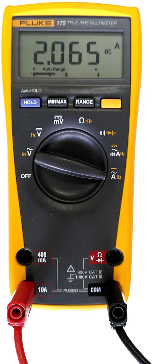
Multimeter checks (do them in this order)
| Check | Meter mode | Power | What you expect |
|---|---|---|---|
| Short between + and GND rails | Continuity / Ω | OFF | No beep, not near 0 Ω (a beep means a short — find it before powering) |
| Is the ground link really connected? | Continuity | OFF | Beep between Arduino GND and battery − |
| Supply voltage | DC volts | ON | Red probe on +, black on GND: close to the expected rail (e.g. near 5 V) |
| KVL on the LED loop | DC volts | ON | V across resistor + V across LED ≈ supply voltage |
| Divider output | DC volts | ON | Measured value close to V_in ÷ 3 for 20 k / 10 k |
Mistakes
Common mistakes and confusions
Think
Think about it
Think
Meera’s robot works perfectly while it is plugged into her laptop over USB. When she unplugs USB and runs everything from the battery pack (the board and the servo on the same pack), the servo works but the board keeps resetting whenever the servo moves. Using circuit thinking, what could be happening and what would you check first?
Experiment
Try it in the lab: close the loop, break the loop
Fifteen to twenty minutes with the Virtual Circuit Builder and your notebook. You will build a correct LED loop, then break it in each classic way and write down what the simulator says — and what would really happen on a bench.
Experiment
Close the loop, break the loop
You will need
- Virtual Circuit Builder (below, runs in your browser)
- Notebook or a text file for a results table
- Optional: your Linux laptop to run `series_parallel.py` and `ground_check.py`
Steps
- Set **Power source = Battery (+)** and **Return / ground = Ground**. Leave the series slots empty and note the status (open).
- Set Series slot 1 = **Resistor**, Series slot 2 = **LED**. Status should be **valid** and the sim LED glows. Write in your notebook: “closed loop, current limited by resistor”.
- Tick **Flip LED polarity**. Note the polarity warning. Untick it again.
- Set Series slot 3 = **Switch**. Untick **Switch closed** — the status becomes open. Tick it again. This is how every power switch on a robot works.
- Clear Series slot 1 (choose — empty —) so only LED and Switch remain. Read the missing-resistor warning and write why this would harm a real LED and GPIO pin.
- Clear Return / ground. Status becomes incomplete: there is no return path. Write one line on why “I wired + but forgot ground” kills a demo.
- Now set source = Battery, Series slot 1 = **Wire** only, the other series slots empty, return = Ground. The sim says valid. In your notebook explain why, on a real bench, this is a **short circuit** (what limits the current?).
- Optional: run `ground_check.py` and match plans B, D and E with the faults you just created in the builder.
Interactive · Virtual Circuit Builder
Build a series loop: battery → parts → ground. Detects open circuit, missing resistor, and LED polarity. Simulated only — never drives real hardware from the browser.
Sim LED · educational · not a datasheet substitute
A circuit works only when the path is closed and something sensible limits the current. The simulator checks the first part; your circuit thinking must always check the second.
Knowledge check
Check your understanding
Knowledge check
1. A valid DC circuit requires…
2. An open switch in series with an LED loop…
3. An Arduino on USB sends a signal to a servo powered by its own battery pack. What must you connect besides the signal wire?
4. In a 5 V series loop, the resistor drops 3.0 V. How much voltage is left for the LED (KVL)?
5. Two LED branches on one rail draw 13.6 mA and 9.1 mA. What current does the rail supply (KCL)?
6. A 20 kΩ (top) / 10 kΩ (bottom) divider is fed 8.4 V. What does the ADC pin see?
7. What is the right way to power a hobby servo in a robot?
Mini assignment
Hands-on assignment
Mini assignment
Robot loop map + circuit check sheet
Draw the full DC circuit of a small robot (real or planned), trace every loop, and prove it with KVL, KCL and a wiring-plan check.
Deliverables
- A hand-drawn or digital diagram of one small robot: board, two status LEDs, one sensor or divider, one servo on its own supply. Mark every + path in red and every return path in black.
- For each load, write the loop in words: “battery + → … → battery −”. Mark which parts are in series and which are in parallel.
- A KVL check on one LED loop and a KCL total for the 5 V (or 3.3 V) rail, with your numbers and units.
- A voltage divider design for a battery you might use: R_top, R_bottom, V_out at full and empty, and one line on why it is safe for your ADC pin (state where you got the battery numbers).
- Your own plan added to `ground_check.py` (the correct version of your robot) with its output pasted — plus one deliberately broken plan and the fault the checker reports.
- Screenshots or notes from the experiment: valid, missing-resistor, polarity, open switch, incomplete, and your explanation of why battery → wire → ground is a short in real life.
Do this, step by step
- In the Virtual Circuit Builder, make a valid LED loop, then break it four ways (no resistor, LED reversed, open switch, missing ground). Note what the builder says each time.
- Draw your robot’s full circuit with + paths in red and return paths in black.
- Write every loop in words: “battery + → … → battery −”.
- Do one KVL check (LED loop) and one KCL total (5 V rail) with units.
- Add your robot to
ground_check.py, run it, then break one ground on purpose and paste both outputs.
Stuck? Hints, one at a time
- Hint 1: Every load needs a way out (from +) and a way back (to −). If you can’t finish the sentence “… → battery −”, that loop is open.
- Hint 2: KVL: the voltages around one loop add up to the supply. For a red LED + 220 Ω on 5 V: about 2.0 V + 3.0 V = 5 V.
- Hint 3: KCL: add every branch current on the rail — e.g. 13.6 mA + 13.6 mA + 15 mA sensor ≈ 42 mA.
- Hint 4: For a 12 V battery read on a 5 V ADC, a 30 kΩ (top) / 10 kΩ (bottom) divider gives 12 × 10 ÷ 40 = 3.0 V.
Challenges (pick by level)
- 🟢 Easy: Three resistors of 100 Ω, 220 Ω and 330 Ω are in series across 5 V. Find the current and the voltage across each, and show KVL holds.
- 🟢 Easy: What is 1 kΩ in parallel with 1 kΩ? And 1 kΩ in parallel with 10 kΩ? Explain in one line why the answer is always below the smallest resistor.
- 🟡 Medium: Design a divider so a 12 V battery reads no more than about 3.0 V on an ADC pin, using standard values. Check it with
divider()inseries_parallel.py. - 🟡 Medium: Add a buzzer branch (use an example current such as 30 mA) to Rahul’s rail and recompute the KCL total. Which part draws the most?
- 🟠 Hard: Extend
ground_check.pywith a second load (a motor driver with its own V+ and GND) and a new rule that flags any load whose GND is not joined to the MCU’s GND. Add a plan that triggers it.
Next step
You now think in loops: out, through, back, and always with a common ground. In Lesson 4 — Resistors, LEDs & Basic Components you will look closely at the parts sitting in those loops: what a resistor really does, why LED polarity matters, and other basics you will meet on every robot board, such as switches, buzzers, pull-ups and connectors.
Tip: explain today’s chapter to a friend with the festival light string and the Mumbai local. If you can say “series is one train line, parallel is many lines from the same station, and every train must come back to the yard” — and then find the missing ground in Rahul’s robot — you have understood DC circuits.
Look back: Lesson 2: Voltage, Current & Resistance. Next: Lesson 4: Resistors, LEDs & Basic Components. Related: Quark Lab EP07 — Kirchhoff’s Laws, Stage 0 — Power & Communication and later Stage 7 — Control Systems.
Sources
Self-attested for now — keep artifacts in your lab notebook.
Complete
Today's goal
0 of 1 done today
Mark this lesson complete when you have worked the experiment, knowledge check, and assignment (even roughly).