
Electronics & Embedded Systems · Lesson 04
Resistors, LEDs & Basic Components
Est. 45–60 min
Why
Why every robot starts with a handful of small parts
In Lesson 2 you used Ohm’s law to size one LED resistor, and in Lesson 3 you learnt to trace loops. Now we zoom into the parts sitting inside those loops. A robot harness may have hundreds of wires, but the first parts you will touch on every board are the same: resistors, LEDs, push buttons and switches, pull-up resistors, potentiometers, buzzers and connectors. Get these right and the bigger parts (motor drivers, sensors, microcontrollers) become much easier.
By the end of this chapter you will be able to read a resistor’s colour bands and SMD code, check its tolerance and power rating, find an LED’s anode and cathode, size its resistor from a real manufacturer datasheet, wire a push button with a pull-up so the input never “floats”, and explain why one press can look like many (switch bounce).
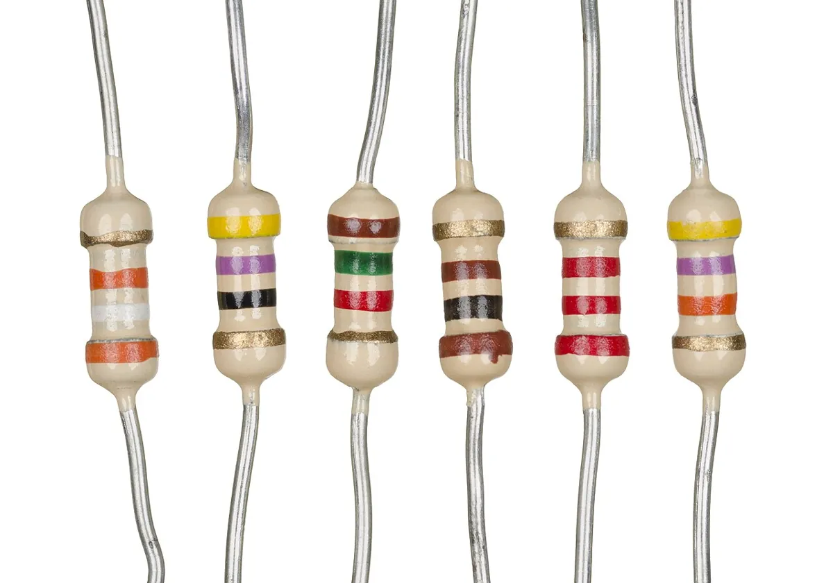
Concept
The big idea: parts with jobs, ratings and a right way round
Think of a robot circuit like a kitchen. The battery is the gas cylinder, the wires are pipes, and each part is a tool with one job. A resistor is the regulator knob that keeps the flame small. An LED is the little indicator lamp on the mixer that shows “ON”. A push button is the switch you press, and a pull-up resistor is the spring that pushes the switch back to a known position when you let go.
| Part | Main job | Polarity? | Rating to check | Robot example |
|---|---|---|---|---|
| Resistor | Limit current, divide voltage, pull an input up or down | No — either way round | Resistance, tolerance, power (W) | 330 Ω in a status-LED loop, 10 kΩ pull-up |
| LED | Turn current into light (a light-emitting diode) | Yes — anode to +, cathode to − | Forward voltage Vf, max current, reverse voltage | “Power on” and “error” lights on every board |
| Push button / switch | Open or close a path on command | Usually no (check the legs that are joined) | Current and voltage rating | Start button, limit switch on an arm |
| Pull-up / pull-down resistor | Give an input a default HIGH or LOW | No | Value (strong vs weak) | Button input, I²C lines |
| Potentiometer | Adjustable resistor / voltage divider | No (but the middle pin is the wiper) | Total resistance, power | Speed knob, joint-angle sensor |
| Buzzer | Turn a signal into sound | Often yes — check the marking | Voltage and current from its datasheet | Low-battery beep |
| Connectors & jumpers | Join parts without solder | Keyed ones only fit one way | Current rating, pitch | Header pins, JST battery plugs |
Resistors: the speed-breakers of a circuit
A resistor has a fixed resistance that limits how much current can flow, exactly like a speed-breaker on a colony road limits how fast cars go. SparkFun lists the three everyday uses: limiting current, dividing voltages and pulling up I/O lines. It has no polarity, so it can go in either way round. Resistance is measured in ohms (Ω); 4,700 Ω is written 4.7 kΩ, and on schematics you may see it written as 4k7.
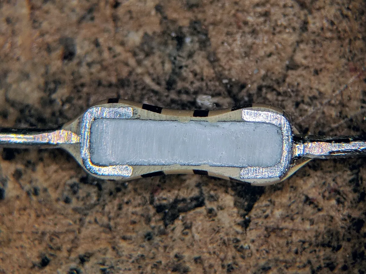
Reading the colour bands
Through-hole resistors are too small to print numbers on, so they wear stripes. The colours follow the international standard IEC 60062 — Vishay’s metal-film datasheet says its “four or five color code rings designate the resistance value and tolerance in accordance with IEC 60062”. On a 4-band resistor, the first two bands are digits, the third is the multiplier (how many zeros), and the last, usually gold (±5 %) or silver (±10 %), is the tolerance. Start reading from the end farthest from the gold or silver band.
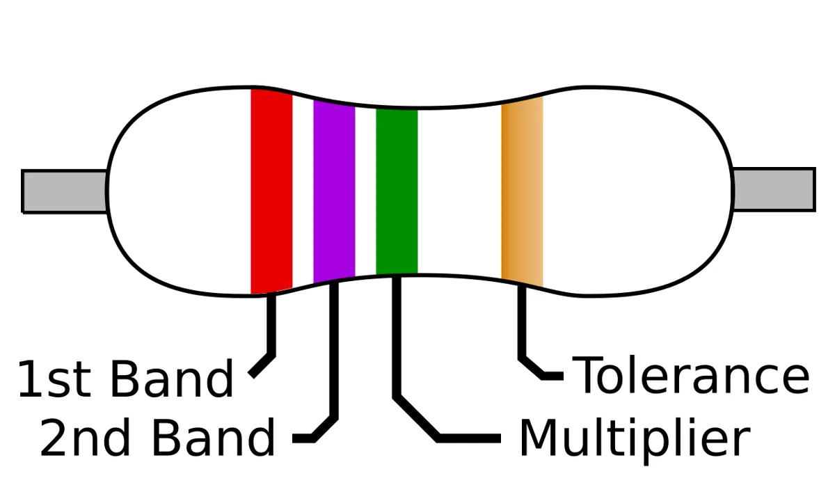
| Colour | Digit | Multiplier | Tolerance |
|---|---|---|---|
| Black | 0 | × 1 | — |
| Brown | 1 | × 10 | ±1 % |
| Red | 2 | × 100 | ±2 % |
| Orange | 3 | × 1 000 | — |
| Yellow | 4 | × 10 000 | — |
| Green | 5 | × 100 000 | ±0.5 % |
| Blue | 6 | × 1 000 000 | ±0.25 % |
| Violet | 7 | × 10 000 000 | ±0.1 % |
| Grey | 8 | × 100 000 000 | — |
| White | 9 | × 1 000 000 000 | — |
| Gold | — | × 0.1 | ±5 % |
| Silver | — | × 0.01 | ±10 % |
Tolerance and standard values
No factory makes a perfect resistor. Tolerance tells you how far off it may be: a 1 kΩ, ±5 % part can measure anywhere from 950 Ω to 1050 Ω (SparkFun’s example). That is why shops sell only certain standard values. Vishay’s datasheet picks values “from E24 series for ±5 %” and from E24/E96 for ±1 %. The shorter E12 series — 10, 12, 15, 18, 22, 27, 33, 39, 47, 56, 68, 82 (times 1, 10, 100 …) — is what most hobby kits contain, which is why you keep seeing 220 Ω, 330 Ω, 4.7 kΩ and 10 kΩ.
Power rating: how much heat a resistor can take
A resistor turns the energy it stops into heat. Its power rating says how much heat it can handle. Most through-hole resistors in kits are ¼ W (about 6.3 mm long) or ½ W (about 9.2 mm), according to SparkFun; tiny SMD parts in 0402 or 0603 size are usually 1/16 W and 0805 about 1/10 W. Ratings also depend on temperature and on the exact part — for example, Vishay rates its 0207-size metal-film resistor at 0.4 W at 70 °C in standard operation. Always read the datasheet of the part you actually bought.
P = V × I = I² × R = V² ÷ R
- P = power turned into heat, in watts (W)
- V = voltage across the resistor (not the whole supply!)
- Good habit: keep P well below the rating — many engineers aim for about half
LEDs: one-way lamps that need a current limit
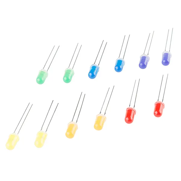
An LED is a diode, a one-way valve for current. Current flows from the anode (+) to the cathode (−) and gives out light. SparkFun’s polarity guide gives two clues: the longer leg is the anode, and if the legs are trimmed, the pin nearest the flat edge of the plastic rim is the cathode. Put it in backwards at low hobby voltages and it simply stays dark — but the datasheet still lists a maximum reverse voltage (5 V for the Kingbright part below), so do not reverse it on higher supplies.
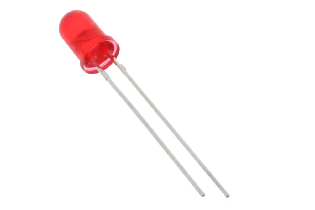
An LED does not limit its own current. Once the voltage reaches its forward voltage (Vf) it conducts more and more, so it needs a series resistor to set a safe current. Vf depends on the colour: SparkFun puts typical values between about 1.7 V and 3.4 V, and says basic LEDs are usually rated around 20 mA continuous. Red LEDs sit at the low end; blue and white at the high end.
| Datasheet line | Value | What it means for you |
|---|---|---|
| Forward voltage VF at IF = 10 mA | 1.9 V typical, 2.3 V max | Use 1.9 V to calculate, check that 2.3 V still works |
| DC forward current (absolute maximum) | 30 mA | Never design at this value — stay comfortably below it |
| Power dissipation (absolute maximum) | 75 mW | Vf × I must stay below this |
| Reverse voltage (absolute maximum) | 5 V | Backwards on a 5 V pin is the limit — never more |
| Peak wavelength at 10 mA | 627 nm | The colour: red |
| Operating temperature | −40 to +85 °C | Fine for indoor robots |
R = (V_supply − Vf) ÷ I_LED
- 5 V pin, Vf = 1.9 V, target 10 mA → R = 3.1 ÷ 0.010 = 310 Ω → next standard value up: 330 Ω
- Check: I = 3.1 ÷ 330 ≈ 9.4 mA (typical) and (5 − 2.3) ÷ 330 ≈ 8.2 mA (worst case) — both far below 30 mA
- Resistor heat: 3.1 V × 9.4 mA ≈ 29 mW — easy for a ¼ W (250 mW) part
Push buttons, pull-ups and pull-downs
A push button only joins two points when you press it. Wire one side to an input pin and the other to GND, and you have a problem: when the button is released, the pin is connected to nothing. SparkFun calls this floating — “there’s no guarantee that a floating pin is either high or low”. It may read HIGH, LOW, or flicker when your hand comes near.
The fix is a pull-up resistor from the pin to VCC (or a pull-down to GND). Released: the resistor gently pulls the pin HIGH. Pressed: the button connects the pin straight to GND, so it reads LOW, and the resistor limits the current so the button does not short VCC to GND. Around 10 kΩ is the usual choice. A low value is a strong pull-up (more current); a high value is a weak one. Fast signals such as USB lines use stronger ones of 1 kΩ to 4.7 kΩ.
Potentiometers, buzzers and connectors
- Potentiometer (pot): two resistors in series with a movable middle tap — an adjustable voltage divider (Lesson 3). Outer pins go to VCC and GND, the middle pin (wiper) goes to an analog input. Robots use pots as speed knobs and as joint-angle sensors inside hobby servos.
- Buzzer: a small sound maker for alerts. Some kinds beep on plain DC, others need a tone signal from the board, and many are polarised — read the module’s datasheet or marking before connecting, and drive anything that needs more current than a pin can safely give through a transistor (Lesson 6).
- Connectors and jumpers: male/female jumper wires, header pins and keyed plugs (the kind that only fit one way) on battery leads. A keyed plug is cheap insurance against reversing a battery.
How it works
How it actually works: bounce, pin limits and why a huge pull-up fails
Switch bounce: one press, many clicks
Inside a push button, two springy metal contacts hit each other. Like a cricket ball dropped on a hard floor, they bounce a few times before settling. The microcontroller is so fast that it can see each bounce as a separate press. Arduino’s official Debounce example solves this by ignoring any change that does not stay steady for 50 ms (“increase if the output flickers”). That is exactly why Ananya’s button counted one press as three.
What a GPIO pin can really give
The ATmega328P datasheet lists 40 mA DC per I/O pin and 200 mA through the VCC and GND pins under *Absolute Maximum Ratings* — values that “may cause permanent damage” if exceeded. Its normal output figures are tested at 20 mA at 5 V. So the right way to think is: about 20 mA is the most you should plan for one pin, and much less is better. A 330 Ω status LED at about 9 mA is a polite load. A motor, a servo or an LED strip is not — those always get their own supply or a driver.
Pin safe
One indicator LED with its own resistor (about 5–15 mA), a button input with a pull-up (well under 1 mA).
Add up the pins
Several LEDs on several pins still share the chip’s total limit. Add the currents (KCL from Lesson 3) and stay well below the totals in the datasheet.
Needs a driver
Motors, servos, relays, LED strips, high-power LEDs and loud buzzers. Use a transistor, MOSFET or driver board with its own supply, and join the grounds (Lesson 6).
Why a 1 MΩ pull-up is too weak
The input pin itself has a very high resistance to ground (SparkFun uses 100 kΩ to 1 MΩ as an example). With a 1 MΩ pull-up you build an accidental voltage divider: the pin sits near half of VCC, about 2.5 V on a 5 V board. The ATmega328P only promises to read HIGH above 0.6 × VCC and LOW below 0.3 × VCC at 5 V, so 2.5 V is a coin toss. Stay in the 10 kΩ–100 kΩ range, or use the built-in pull-up.
Visual
Visualise it: resistor, LED and switch in the Virtual Circuit Builder
Put Battery in the Power source slot and Ground in the Return slot. Build Resistor + LED (valid, the sim LED glows), then remove the Resistor (missing-resistor warning) and tick Flip LED polarity (polarity warning). Add a Switch and untick “Switch closed” to see an open loop. Browser simulation only — it checks paths and part order, not real currents, and never drives hardware.
Interactive · Virtual Circuit Builder
Build a series loop: battery → parts → ground. Detects open circuit, missing resistor, and LED polarity. Simulated only — never drives real hardware from the browser.
Sim LED · educational · not a datasheet substitute
Worked example
Worked example: fixing Ananya’s status panel
Ananya’s robot needs a red “ready” LED and a start button on an Arduino Uno-style 5 V board. Her senior, Kabir, asks her to redo it properly, part by part, with the datasheet open.
Step 1: Read the resistor before using it
- Her “4.7 kΩ” resistor reads yellow–violet–black–gold. Black means × 1, so it is 47 Ω, not 4.7 kΩ (that would be yellow–violet–red).
- 47 Ω on a 5 V pin with a red LED would allow (5 − 1.9) ÷ 47 ≈ 66 mA — over the LED’s 30 mA limit and over the pin’s 40 mA absolute maximum. That explains the first dead LED.
- Lesson: always read the third band carefully, and confirm with a multimeter in Ω mode when unsure.
Step 2: Size the LED resistor from the datasheet
- Kingbright WP7113ID: Vf = 1.9 V typical (2.3 V max) at 10 mA.
- R = (5.0 − 1.9) ÷ 0.010 = 310 Ω → next standard value up is 330 Ω (orange–orange–brown).
- Current ≈ 9.4 mA typical, ≈ 8.2 mA worst case. LED power ≈ 18 mW (limit 75 mW).
- Resistor heat ≈ 29 mW — about one-ninth of a ¼ W rating. Cool and safe.
Step 3: Put the LED the right way round
- D9 → 330 Ω → LED anode (long leg) → LED cathode (flat side) → GND.
- The resistor may go on either side of the LED — it is in series, so the same current flows (Lesson 3).
Step 4: Give the button a pull-up and debounce it
- Button between D2 and GND. Turn on the internal pull-up with
INPUT_PULLUP(20–50 kΩ inside the chip). - Released = HIGH, pressed = LOW. Pressed current = 5 V ÷ 20–50 kΩ = 0.1–0.25 mA.
- In code, accept a change only after it has been steady for 50 ms. One press now counts as one.
| Part | Value / marking | Rating check | Direction | Verdict |
|---|---|---|---|---|
| Old resistor | Yellow–violet–black = 47 Ω | 66 mA through LED — over limits | — | REPLACE |
| LED resistor | Orange–orange–brown = 330 Ω ±5 % | 29 mW of 250 mW | Either way | OK |
| Red LED | WP7113ID, Vf 1.9 V | 9.4 mA of 30 mA max, 18 mW of 75 mW | Long leg to D9 side | OK |
| Start button | Internal pull-up 20–50 kΩ | 0.1–0.25 mA when pressed | Check which legs are joined | OK |
| Debounce | 50 ms in code | — | — | OK |
Code lab
Code lab: a resistor toolkit and a button simulator in Python
No hardware needed. Both scripts only do arithmetic and print. Copy them into a file on your Linux laptop (from Stage 3) and run them with python3. The outputs below were captured by actually running these exact files.
1. Colour bands, SMD codes, heat and a real LED datasheet
This script reads 4- and 5-band colour codes (and shows the real range allowed by the tolerance), decodes SMD markings such as 104, checks whether a resistor will overheat with P = V² ÷ R, and finally repeats Kabir’s LED calculation using the Kingbright WP7113ID datasheet numbers.
# resistor_toolkit.py — read colour bands, check tolerance and heat, size an LED resistor
# from a real datasheet (Stage 4, Lesson 4). Simulation only: plain arithmetic that prints.
# No pins, no ports, no hardware. Colour code per IEC 60062 (as used on Vishay/SparkFun parts).

DIGITS = {"black": 0, "brown": 1, "red": 2, "orange": 3, "yellow": 4,
          "green": 5, "blue": 6, "violet": 7, "grey": 8, "white": 9}
MULTIPLIER = {**{c: 10 ** d for c, d in DIGITS.items()}, "gold": 0.1, "silver": 0.01}
TOLERANCE = {"brown": 1, "red": 2, "green": 0.5, "blue": 0.25, "violet": 0.1,
             "gold": 5, "silver": 10}


def nice(ohm):
    """Show 4700 as 4.7 kOhm, 2700000 as 2.7 MOhm."""
    for limit, unit in ((1e6, "M"), (1e3, "k")):
        if ohm >= limit:
            return f"{ohm / limit:g} {unit}Ohm"
    return f"{ohm:g} Ohm"


def decode(bands):
    """4 bands = 2 digits + multiplier + tolerance; 5 bands = 3 digits + multiplier + tolerance."""
    *digit_bands, mult, tol = bands
    value = 0
    for colour in digit_bands:
        value = value * 10 + DIGITS[colour]
    ohm = round(value * MULTIPLIER[mult], 4)
    pct = TOLERANCE[tol]
    low, high = ohm * (1 - pct / 100), ohm * (1 + pct / 100)
    print(f"  {'-'.join(bands):<34} -> {nice(ohm)} +/-{pct}%  (real part: {nice(round(low, 2))} to {nice(round(high, 2))})")
    return ohm


def smd(code):
    """3-digit SMD code: two digits, then the number of zeros. '104' = 10 x 10^4."""
    ohm = int(code[:2]) * 10 ** int(code[2])
    print(f"  SMD '{code}' -> {nice(ohm)}")


def heat(name, volts_across, ohm, rating_w):
    p = volts_across ** 2 / ohm                      # P = V^2 / R
    verdict = "OK" if p <= rating_w / 2 else ("WARM - pick a bigger rating" if p <= rating_w else "OVER RATING - it will overheat")
    print(f"  {name:<34} P = {p * 1000:7.1f} mW of {rating_w * 1000:.0f} mW rating -> {verdict}")


print("1) Reading colour bands (first band is the one farthest from the gold/silver band)")
print("-" * 78)
decode(["yellow", "violet", "red", "gold"])          # SparkFun's 4.7 k example
decode(["orange", "orange", "brown", "gold"])        # 330 Ohm, the common LED resistor
decode(["brown", "black", "orange", "gold"])         # 10 k pull-up
decode(["red", "violet", "green", "gold"])           # the 2.7 M diagram in this chapter
decode(["brown", "black", "black", "red", "brown"])  # 5-band 10 k, 1 %

print()
print("2) Tiny SMD resistors print numbers instead of bands")
print("-" * 78)
for c in ("104", "331", "472"):
    smd(c)

print()
print("3) Is the resistor going to get hot?  (keep P below about half the rating)")
print("-" * 78)
heat("330 Ohm LED resistor, 3.1 V", 3.1, 330, 0.25)
heat("10 k pull-up, button pressed, 5 V", 5.0, 10_000, 0.25)
heat("47 Ohm across 5 V (wrong part!)", 5.0, 47, 0.25)
heat("10 Ohm across 5 V (very wrong)", 5.0, 10, 0.25)

print()
print("4) Size an LED resistor from a real datasheet: Kingbright WP7113ID (5 mm red)")
print("-" * 78)
VF_TYP, VF_MAX = 1.9, 2.3      # forward voltage at 10 mA (datasheet typ / max)
IF_ABS_MAX = 0.030             # absolute maximum DC forward current, 30 mA
PD_LED_MAX = 0.075             # absolute maximum LED power dissipation, 75 mW
v_supply, target = 5.0, 0.010  # 5 V pin, aim for the datasheet's 10 mA test current
r_exact = (v_supply - VF_TYP) / target
E12 = [10, 12, 15, 18, 22, 27, 33, 39, 47, 56, 68, 82]
r_pick = next(b * d for d in (1, 10, 100, 1000) for b in E12 if b * d >= r_exact)
for label, vf in (("typical LED", VF_TYP), ("worst-case LED", VF_MAX)):
    i = (v_supply - vf) / r_pick
    print(f"  {label:<15} Vf {vf} V -> I = {i * 1000:4.1f} mA (abs max {IF_ABS_MAX * 1000:.0f} mA), "
          f"LED power {vf * i * 1000:4.1f} mW (max {PD_LED_MAX * 1000:.0f} mW)")
print(f"  exact R = {r_exact:.0f} Ohm -> standard E12 part {r_pick} Ohm (orange-orange-brown)")
heat("that resistor", v_supply - VF_TYP, r_pick, 0.25)
Output (run with python3 resistor_toolkit.py)
1) Reading colour bands (first band is the one farthest from the gold/silver band)
------------------------------------------------------------------------------
  yellow-violet-red-gold             -> 4.7 kOhm +/-5%  (real part: 4.465 kOhm to 4.935 kOhm)
  orange-orange-brown-gold           -> 330 Ohm +/-5%  (real part: 313.5 Ohm to 346.5 Ohm)
  brown-black-orange-gold            -> 10 kOhm +/-5%  (real part: 9.5 kOhm to 10.5 kOhm)
  red-violet-green-gold              -> 2.7 MOhm +/-5%  (real part: 2.565 MOhm to 2.835 MOhm)
  brown-black-black-red-brown        -> 10 kOhm +/-1%  (real part: 9.9 kOhm to 10.1 kOhm)

2) Tiny SMD resistors print numbers instead of bands
------------------------------------------------------------------------------
  SMD '104' -> 100 kOhm
  SMD '331' -> 330 Ohm
  SMD '472' -> 4.7 kOhm

3) Is the resistor going to get hot?  (keep P below about half the rating)
------------------------------------------------------------------------------
  330 Ohm LED resistor, 3.1 V        P =    29.1 mW of 250 mW rating -> OK
  10 k pull-up, button pressed, 5 V  P =     2.5 mW of 250 mW rating -> OK
  47 Ohm across 5 V (wrong part!)    P =   531.9 mW of 250 mW rating -> OVER RATING - it will overheat
  10 Ohm across 5 V (very wrong)     P =  2500.0 mW of 250 mW rating -> OVER RATING - it will overheat

4) Size an LED resistor from a real datasheet: Kingbright WP7113ID (5 mm red)
------------------------------------------------------------------------------
  typical LED     Vf 1.9 V -> I =  9.4 mA (abs max 30 mA), LED power 17.8 mW (max 75 mW)
  worst-case LED  Vf 2.3 V -> I =  8.2 mA (abs max 30 mA), LED power 18.8 mW (max 75 mW)
  exact R = 310 Ohm -> standard E12 part 330 Ohm (orange-orange-brown)
  that resistor                      P =    29.1 mW of 250 mW rating -> OK
2. Floating pins, pull-ups and bounce
This script shows what a floating input can read (random numbers stand in for electrical noise), what happens with an external 10 kΩ pull-up and with the internal 20–50 kΩ one, why a 1 MΩ pull-up is too weak, and how a 50 ms debounce turns a bouncy press into exactly one press.
# button_pullup.py — why a push button needs a pull-up (or pull-down) resistor,
# and why one press can look like many (bounce). Stage 4, Lesson 4.
# Simulation only: plain arithmetic and a fake signal. No pins, no ports, no hardware.
import random

VCC = 5.0
V_HIGH_MIN, V_LOW_MAX = 0.6 * VCC, 0.3 * VCC   # ATmega328P-style input thresholds at 5 V


def logic(v):
    if v >= V_HIGH_MIN:
        return "HIGH"
    if v <= V_LOW_MAX:
        return "LOW"
    return "UNKNOWN (could read either!)"


print("1) Button on an input pin, three ways")
print("-" * 70)
random.seed(1)           # fixed seed so the output below repeats exactly
print("  a) No resistor (floating) — the pin picks up noise from fingers, wires, the air:")
for _ in range(5):
    v = random.uniform(0.0, VCC)      # random numbers stand in for noise: a floating pin has no defined voltage
    print(f"     reads {v:4.2f} V -> {logic(v)}")
print("  b) 10 k pull-up to 5 V, button to GND:")
print(f"     released: pin = {VCC:.1f} V -> {logic(VCC)}   pressed: pin = 0.0 V -> {logic(0.0)}")
print(f"     current when pressed = 5 V / 10 k = {VCC / 10_000 * 1000:.2f} mA (tiny, safe)")
print("  c) Internal pull-up (INPUT_PULLUP), datasheet range 20 k to 50 k:")
for r in (20_000, 50_000):
    print(f"     R = {r // 1000} k -> current when pressed = {VCC / r * 1000:.2f} mA")
print("     Logic is inverted: released = HIGH, pressed = LOW.")

print()
print("2) Why a huge pull-up fails: it forms a divider with the pin's input resistance")
print("-" * 70)
R_INPUT = 1_000_000                  # SparkFun's example input impedance, ~1 MOhm
for r_pull in (10_000, 100_000, 1_000_000):
    v_pin = VCC * R_INPUT / (r_pull + R_INPUT)
    print(f"  pull-up {r_pull // 1000:>5} k -> pin sits at {v_pin:4.2f} V -> {logic(v_pin)}")

print()
print("3) Bounce: one press, many edges. Ignore changes that do not last 50 ms")
print("-" * 70)
# One sample per millisecond. 1 = released (pull-up), 0 = pressed. Contacts chatter for a few ms.
raw = [1] * 20 + [0, 1, 0, 0, 1, 0, 1, 0] + [0] * 120 + [1, 0, 1] + [1] * 80
edges = sum(1 for a, b in zip(raw, raw[1:]) if a != b)
stable, last_change, candidate, presses = 1, 0, 1, 0
for t, s in enumerate(raw):
    if s != candidate:
        candidate, last_change = s, t
    if t - last_change >= 50 and candidate != stable:
        stable = candidate
        if stable == 0:
            presses += 1
            print(f"  t = {t:3d} ms  press accepted")
print(f"  raw signal changed {edges} times; debounced presses counted = {presses}")
Output (run with python3 button_pullup.py)
1) Button on an input pin, three ways
----------------------------------------------------------------------
  a) No resistor (floating) — the pin picks up noise from fingers, wires, the air:
     reads 0.67 V -> LOW
     reads 4.24 V -> HIGH
     reads 3.82 V -> HIGH
     reads 1.28 V -> LOW
     reads 2.48 V -> UNKNOWN (could read either!)
  b) 10 k pull-up to 5 V, button to GND:
     released: pin = 5.0 V -> HIGH   pressed: pin = 0.0 V -> LOW
     current when pressed = 5 V / 10 k = 0.50 mA (tiny, safe)
  c) Internal pull-up (INPUT_PULLUP), datasheet range 20 k to 50 k:
     R = 20 k -> current when pressed = 0.25 mA
     R = 50 k -> current when pressed = 0.10 mA
     Logic is inverted: released = HIGH, pressed = LOW.

2) Why a huge pull-up fails: it forms a divider with the pin's input resistance
----------------------------------------------------------------------
  pull-up    10 k -> pin sits at 4.95 V -> HIGH
  pull-up   100 k -> pin sits at 4.55 V -> HIGH
  pull-up  1000 k -> pin sits at 2.50 V -> UNKNOWN (could read either!)

3) Bounce: one press, many edges. Ignore changes that do not last 50 ms
----------------------------------------------------------------------
  t =  77 ms  press accepted
raw signal changed 10 times; debounced presses counted = 1Simulator
Try it in the simulator
Simulator · Electronics
Ohm's law & LED resistor calculator
Pick a supply, LED forward voltage and target current; get the resistor, the nearest standard value and the power.
Loading simulator…
Formulas used
- V = I·R
- R = (Vs − Vf) / I
- I_actual = (Vs − Vf) / R_E12
- P_R = I²·R
Model & limits
LED modelled as a constant forward voltage Vf (real Vf changes a little with current and temperature; check the datasheet).
Want to draft this circuit? Open Station Engine (a drafting workbench, no simulation yet).
Real world
Where these parts live on real robots
- Status LEDs on every board: Arduino boards, motor drivers and robot controllers use small LEDs with series resistors to show power, communication and errors — the first thing to check when a robot “does nothing”.
- Limit switches on arms and 3D printers: a switch with a pull-up tells the controller when a joint or axis reaches its end, so it can stop or home itself.
- Start/stop buttons on competition robots: a debounced start button with a pull-up is standard on line followers and sumo bots at college tech fests.
- Pull-ups on communication lines: I²C sensor buses rely on pull-up resistors on their data and clock lines (the ATmega328P datasheet notes the TWI bus needs “a single pull-up resistor for each of the TWI bus lines”).
- Potentiometers as sensors: hobby servos use a pot inside to measure their own angle — a voltage divider you will meet again in control lessons.
- Current-limiting everywhere: from phone indicator lights to industrial panel lamps, an LED always has something limiting its current — a resistor or a dedicated driver.
On the bench
On a real bench: wiring an LED and a button safely
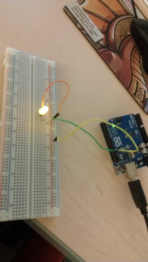
When you have a board, a breadboard and the parts, build the status panel in this order. The sketch below is for a real Arduino Uno-style board and is not run inside the browser.
Power off while wiring
Unplug USB before adding or moving wires. Wire, check, then power.
Measure the resistor
Before it goes in, put the multimeter in Ω mode across the resistor. 330 Ω ±5 % should read between about 313 Ω and 347 Ω.
LED loop
D9 → 330 Ω → LED long leg (anode). LED short leg / flat side (cathode) → GND rail. Each LED gets its own resistor.
Button
Place the button across the breadboard’s centre gap. Use a continuity test to find which legs are joined when pressed, then wire one side to D2 and the other to GND.
Power and test
Plug in USB, upload
led_button.ino, open the Serial Monitor at 9600 baud and press the button. Each press should toggle the LED and print exactly one line.
// led_button.ino — status LED + push button on an Arduino Uno (Stage 4, Lesson 4)
// For a REAL board on your bench. This sketch is not run inside the browser.
// Wiring: D9 -> 330 ohm -> LED anode (long leg); LED cathode (flat side) -> GND.
//         D2 -> one side of the push button; other side of the button -> GND.
// The internal pull-up (INPUT_PULLUP) keeps D2 HIGH until the button pulls it LOW.

const int LED_PIN = 9;
const int BUTTON_PIN = 2;
const unsigned long DEBOUNCE_MS = 50;   // same idea as Arduino's Debounce example

int stableState = HIGH;         // released = HIGH because of the pull-up
int lastReading = HIGH;
unsigned long lastChange = 0;
bool ledOn = false;

void setup() {
  pinMode(LED_PIN, OUTPUT);
  pinMode(BUTTON_PIN, INPUT_PULLUP);
  Serial.begin(9600);
}

void loop() {
  int reading = digitalRead(BUTTON_PIN);
  if (reading != lastReading) {          // contacts moved (or bounced)
    lastChange = millis();
    lastReading = reading;
  }
  if (millis() - lastChange > DEBOUNCE_MS && reading != stableState) {
    stableState = reading;
    if (stableState == LOW) {            // a real, settled press
      ledOn = !ledOn;
      digitalWrite(LED_PIN, ledOn ? HIGH : LOW);
      Serial.println(ledOn ? "LED ON" : "LED OFF");
    }
  }
}| Check | Meter mode | Power | What you expect |
|---|---|---|---|
| Resistor value | Ω | OFF (part out of circuit) | Within tolerance of the colour-band value |
| LED direction | Diode test | OFF | Glows faintly / shows a reading one way only |
| Button legs | Continuity | OFF | Beep only while pressed, between the legs you wired |
| Voltage across the 330 Ω | DC volts | ON, LED lit | About 3 V on a 5 V board → I ≈ 3 V ÷ 330 Ω ≈ 9 mA |
| D2 with button released | DC volts | ON | Close to 5 V (pull-up working) |
Mistakes
Common mistakes and confusions
Debugging
Debugging: when it doesn’t work
| Symptom | Likely cause | Fix |
|---|---|---|
| LED stays off | LED reversed (flat side / short leg = cathode to GND) | Turn it round |
| Button reads random HIGH/LOW | Input floating — no pull-up | Use INPUT_PULLUP or a 10 kΩ pull-up |
| Button reads “pressed” all the time | Button legs on the same internal side, or wired across the wrong pair | Rotate the button 90° on the breadboard |
| Resistor value doesn’t match colour code | Read from the wrong end (gold/silver band goes on the right) | Re-read; confirm with the meter |
Think
Think about it
Think
Rohan wires three LEDs — red, green and blue — in parallel from one 5 V pin through a single shared 100 Ω resistor. Only the red one glows brightly, the blue one hardly glows, and after a while the board resets when all are on. Using today’s ideas (Vf, series resistors, pin limits), explain what is happening and how you would rewire it.
Experiment
Try it in the lab: the polarity and resistor drill
Fifteen minutes with the Virtual Circuit Builder and your notebook. You will build a correct LED loop, then break it in the ways beginners usually do, and write down what would happen on a real bench.
Experiment
Polarity and resistor drill
You will need
- Virtual Circuit Builder (below, runs in your browser)
- Notebook or a text file for a results table
- Optional: your Linux laptop to run `resistor_toolkit.py` and `button_pullup.py`
Steps
- Set **Power source = Battery (+)** and **Return / ground = Ground**. Set Series slot 1 = **Resistor**, Series slot 2 = **LED**. The status should be valid and the sim LED glows. Write: “330 Ω limits the current to about 9 mA (Kingbright example)”.
- Tick **Flip LED polarity**. Note the polarity warning. In your notebook write which leg (long or short) should face the + side. Untick it again.
- Clear Series slot 1 so only the LED remains. Read the missing-resistor warning. Use `resistor_toolkit.py` thinking to write what current a 47 Ω or 0 Ω path would allow on 5 V.
- Put the Resistor back. Set Series slot 3 = **Switch** and untick **Switch closed**. The loop opens. Write how a pull-up would make an *input* pin read when this switch is open.
- Tick Switch closed again. Now write a one-line part check for each part in the loop: job, value/rating, direction.
- Optional: run `button_pullup.py`, then change the debounce window to 2 ms and record how many presses it counts.
Interactive · Virtual Circuit Builder
Build a series loop: battery → parts → ground. Detects open circuit, missing resistor, and LED polarity. Simulated only — never drives real hardware from the browser.
Sim LED · educational · not a datasheet substitute
A working LED circuit needs three things at once: a closed loop, the LED the right way round, and something sensible limiting the current. The simulator checks the first two and warns about the resistor; the numbers — and the datasheet — are your job.
Knowledge check
Check your understanding
Knowledge check
1. LEDs need a series resistor mainly to…
2. On a new 5 mm LED, which leg is the anode (+)?
3. A resistor has bands yellow–violet–red–gold. What is it?
4. A 1 kΩ, ±5 % resistor can actually measure…
5. Using the Kingbright WP7113ID (Vf 1.9 V) on a 5 V pin at about 10 mA, which standard resistor is the best choice?
6. A 47 Ω, ¼ W resistor is placed directly across 5 V. What happens?
7. A pull-up resistor on a button input is used to…
8. With `pinMode(2, INPUT_PULLUP)` and a button from pin 2 to GND, what does `digitalRead(2)` return while the button is pressed?
9. Why might one button press be counted three times?
10. Which of these may you safely power directly from an Arduino Uno GPIO pin?
Mini assignment
Hands-on assignment
Mini assignment
Robot parts card set + status panel plan
Make a part card for each basic component and design a safe LED + button status panel for a small robot, with numbers from real datasheets.
Deliverables
- Five part cards (resistor, LED, push button, pull-up, potentiometer): for each, the job, the value or marking, the rating to check, the direction (if any) and one robot use.
- Decode at least four resistors from your own kit (or the photo in this chapter) by colour bands, then confirm each with a multimeter if you have one. Note the tolerance range.
- Find the datasheet of one LED you own (or use the Kingbright WP7113ID). Copy its Vf, maximum DC current and reverse voltage, then calculate a resistor for a 5 V and a 3.3 V board. Show the heat in the resistor.
- A wiring diagram of a status panel: two LEDs (different colours, each with its own resistor) and one start button with a pull-up. Mark anode/cathode and which pin each part uses.
- Run `resistor_toolkit.py` and `button_pullup.py` with one change each (from the Play with it tips) and paste the new output.
- Notes from the experiment: valid, polarity-flipped, missing-resistor and open-switch cases, with one sentence each on what would happen on a real bench.
Do this, step by step
- Decode four resistors from your kit (or the photo) by colour, then measure each with a meter. Write value, tolerance and measured value.
- Look up one LED datasheet (Kingbright WP7113ID is fine). Copy Vf, max DC current and reverse voltage.
- Calculate the resistor for that LED on 5 V and on 3.3 V, and the resistor heat.
- Draw the status panel: two LEDs with their own resistors + one start button with a pull-up.
- Run
resistor_toolkit.pyandbutton_pullup.pywith one change each and paste the output.
Stuck? Hints, one at a time
- Hint 1: Read colour bands with the gold/silver tolerance band on the right. Brown-black-red = 1 kΩ, red-red-brown = 220 Ω.
- Hint 2: A measured value is fine if it sits inside the tolerance — a 5% 1 kΩ can read 950–1050 Ω.
- Hint 3: With
INPUT_PULLUPthe pin reads HIGH when the button is released and LOW when pressed — your code should treat LOW as “pressed”. - Hint 4: Each LED needs its own resistor; sharing one resistor between LEDs in parallel makes one hog the current.
Challenges (pick by level)
- 🟢 Easy: Decode brown–black–orange–gold and red–red–brown–gold. Which one would you use as a pull-up and which for an LED?
- 🟢 Easy: What does the SMD code 222 mean? And 101?
- 🟡 Medium: A 3.3 V board drives a red Kingbright WP7113ID. Choose a standard resistor for about 5 mA and check the worst-case current with Vf = 2.3 V.
- 🟡 Medium: Add a
pull_downcase tobutton_pullup.py(resistor to GND, button to VCC) and print released/pressed logic levels. - 🔴 Hard: Extend
resistor_toolkit.pysodecode()also prints the E12 or E24 neighbours of any value, and flags band combinations that are not standard values. - 🔴 Hard: Modify
led_button.ino(on a real board) so a long press (over 1 second) blinks the LED three times and a short press toggles it.
Next step
You can now read, choose and safely wire the small parts in every robot loop. In Lesson 5 — Capacitors & Power Stability you will meet the part that smooths the sudden dips when servos and motors start — the reason Meera’s board kept resetting in Lesson 3.
Tip: explain today’s chapter with the kitchen picture. If you can say “the resistor is the regulator knob, the LED is a one-way indicator lamp with a long + leg, and the pull-up is the spring that keeps the switch in a known position” — and then size Ananya’s 330 Ω resistor from a datasheet — you have understood basic components.
Look back: Lesson 3: DC Circuits & Circuit Thinking. Next: Lesson 5: Capacitors & Power Stability. Related: Stage 0 — Sensors and Stage 2 — Python + Sensors.
Sources
- Kingbright WP7113ID 5 mm red LED datasheet — Vf, maximum current, power, reverse voltage, wavelength.
- Vishay MBA/SMA 0204, MBB/SMA 0207, MBE/SMA 0414 metal film resistor datasheet — IEC 60062 colour code, tolerance, E-series, rated dissipation.
- Microchip ATmega48A/PA/88A/PA/168A/PA/328/P datasheet — 40 mA per I/O pin absolute maximum, 20–50 kΩ pull-ups, input thresholds.
- SparkFun Learn: Resistors — uses, colour bands, SMD codes, power ratings, pull-ups.
- SparkFun Learn: Light-Emitting Diodes (LEDs) — polarity, forward voltage, current limiting, reading LED datasheets.
- SparkFun Learn: Pull-up Resistors — floating inputs, strong vs weak pull-ups, input impedance.
- SparkFun Learn: Polarity — LED anode/cathode, longer leg and flat edge.
- Arduino example: Input Pull-up Serial —
INPUT_PULLUP, inverted button logic. - Arduino example: Debounce — 50 ms debounce delay.
- Photos and diagram: Wikimedia Commons (credits under each image).
Self-attested for now — keep artifacts in your lab notebook.
Complete
Today's goal
0 of 1 done today
Mark this lesson complete when you have worked the experiment, knowledge check, and assignment (even roughly).