
Electronics & Embedded Systems · Lesson 05
Capacitors & Power Stability
Est. 45–60 min
Why
Why your robot resets the moment a servo moves
In Lessons 2–4 you learnt voltage, current, loops and the small parts inside them. Every circuit so far assumed the supply was a perfect, steady 5 V. Real supplies are not. Motors and servos draw current in sudden bursts, digital chips switch millions of times a second, and every wire has a little resistance. Power stability is the art of keeping the voltage steady at the place where it is used. Capacitors are the most important tool for that job — and knowing their limits is just as important.
By the end of this chapter you will be able to explain what a capacitor stores, read its value and voltage rating, tell a polarised electrolytic from a ceramic, calculate charge, energy and the RC time constant, place decoupling and bulk capacitors correctly on a servo board, pick a safe voltage rating, and — most importantly — tell when a problem needs a capacitor and when it needs a better power supply.
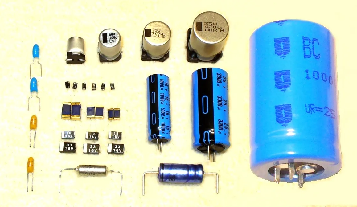
Concept
The big idea: a capacitor is a small local water tank for charge
Think of the water supply in an Indian apartment. The municipal pipeline is the power supply. The long pipe up the building is the wire, with its own friction (resistance). The overhead tank on your floor is the capacitor. When everyone opens their taps at 7 a.m., the tank keeps the pressure steady for a while because it is close by and already full. But if the pipeline is too weak for the whole building, the tank empties and the taps go dry anyway. A capacitor does exactly this for electric charge: it is a small, local store that covers short gulps of current. It cannot replace a supply that is too small.
What is inside a capacitor
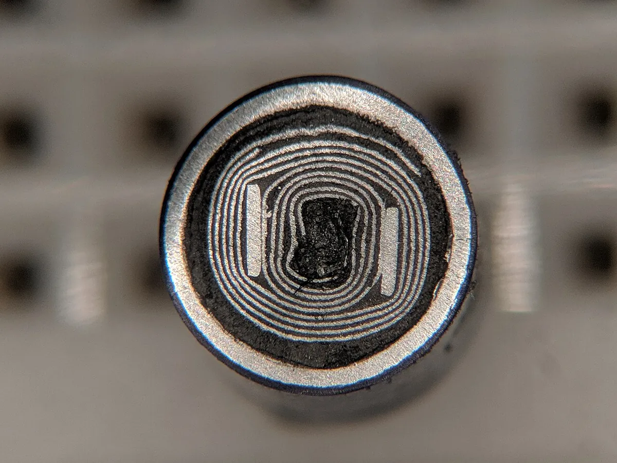
SparkFun’s tutorial describes the classic build: two metal plates placed very close together with an insulating dielectric between them so they never touch. Charge cannot cross the dielectric, so it piles up — negative on one plate, positive on the other. The electric field between the plates stores energy. More plate area and a thinner gap give more capacitance; the dielectric material matters too.
Capacitance, charge and energy
Capacitance (C) is measured in farads (F). One farad is huge, so robot boards use picofarads (pF), nanofarads (nF) and microfarads (µF): 1 µF = 1000 nF = 1 000 000 pF. The charge stored grows with the voltage across the plates:
Q = C × V and E = ½ × C × V²
- Q = charge in coulombs (C), V = voltage across the capacitor, C = capacitance in farads
- E = energy stored in joules (OpenStax: U = ½CV²)
- Example: 1000 µF at 6 V stores 6 mC of charge and only 18 mJ of energy — tiny compared with a battery
The one rule that explains everything: capacitors resist sudden voltage change
SparkFun gives the key relation in words: the current through a capacitor depends on its capacitance and on how quickly the voltage is rising or falling (I = C × dV/dt). If the voltage is steady, no current flows through it. So for steady DC a capacitor behaves like an open gap, but the moment the rail tries to drop quickly, the capacitor pushes charge out to fight that change. That is why SparkFun calls them “stubborn components” that “always try to resist sudden changes in voltage”.
I = C × dV/dt
- Rail falling fast (big dV/dt) → the capacitor supplies a big current
- Rail steady (dV/dt = 0) → no current, the capacitor just sits there, charged
- Turned around: ΔV ≈ I × Δt ÷ C — a bigger C means a smaller dip for the same gulp of current
Charging and discharging take time: the RC time constant
A capacitor charged through a resistor does not fill instantly. OpenStax derives Vc = V₀(1 − e^(−t/RC)) and names τ = R × C the time constant. After one τ the capacitor reaches about 63.2 % of the final voltage; after about five τ it is practically full (99.3 %). Discharging follows the same curve downwards. This one idea tells you how fast a bulk capacitor can refill, and how long to wait after switching off before you touch a board.
| Time | Charged to | What it means |
|---|---|---|
| 1 τ | 63.2 % | Most of the way there |
| 2 τ | 86.5 % | Nearly full |
| 3 τ | 95.0 % | Good enough for most timing |
| 5 τ | 99.3 % | Treat as full (or fully discharged, going the other way) |
The two capacitors every robot board has
| Property | Ceramic (MLCC / disc) | Aluminium electrolytic |
|---|---|---|
| Typical values | pF up to about 10 µF (SparkFun: rarely much larger) | About 1 µF to 1 mF and more |
| Polarity | None — fit either way | Polarised — stripe/− marks the negative lead |
| Strength | Very low ESR and leakage; great at high frequency | Lots of capacitance in a small can |
| Typical job | Decoupling right at chip power pins (0.1 µF) | Bulk storage on a servo or motor rail (100s of µF) |
| Watch out for | Value drops with DC voltage on X5R/X7R types (Murata: DC bias) | Reverse voltage, over-voltage, heat, ageing |
| Tolerance | Depends on type | ±20 % is common (Nichicon UVR: ±20 % at 120 Hz) |
Reading capacitor markings
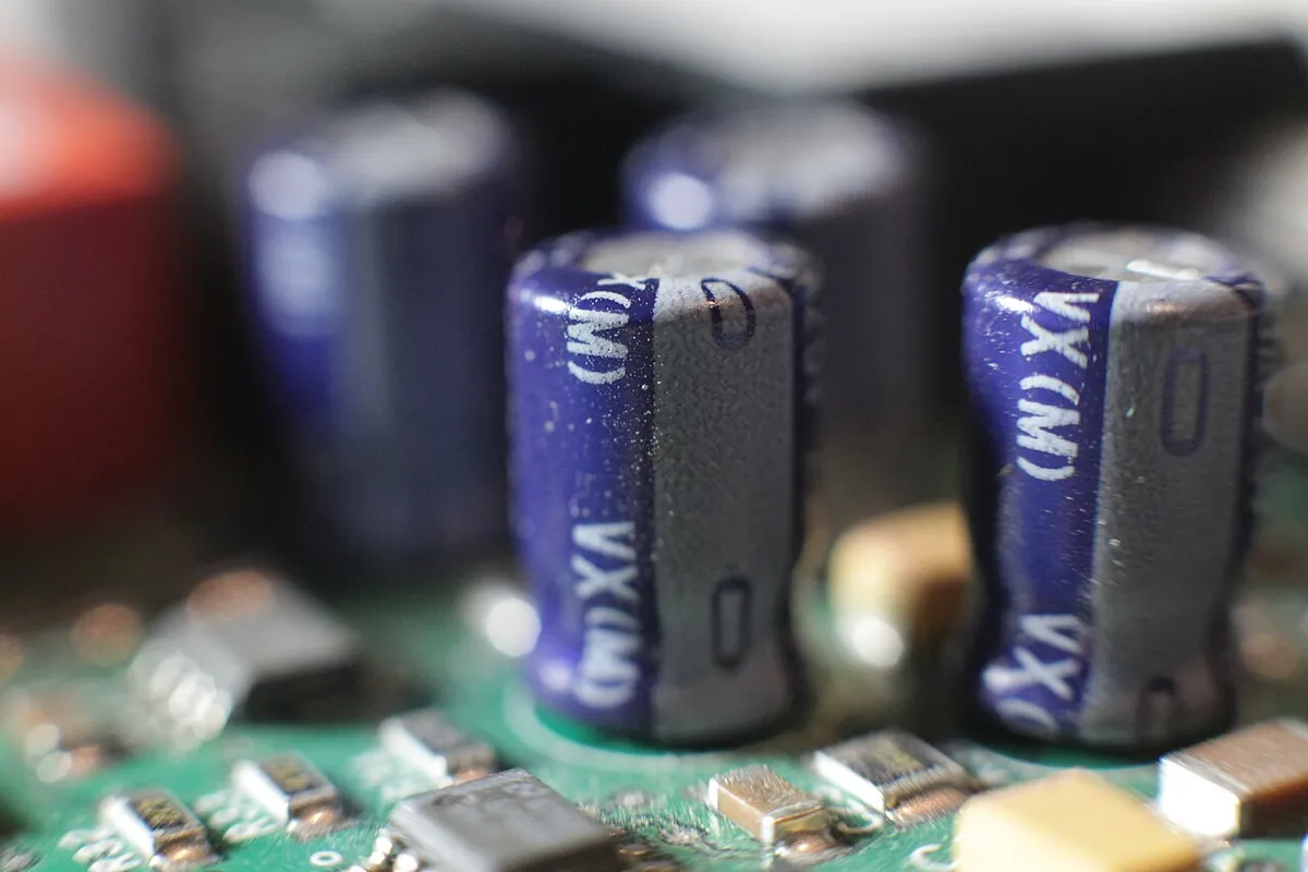
- Electrolytics print the value and voltage plainly, e.g. “1000 µF 16 V”, plus a stripe with − signs on the negative side. SparkFun notes the anode (+) leg may also be slightly longer on a new part.
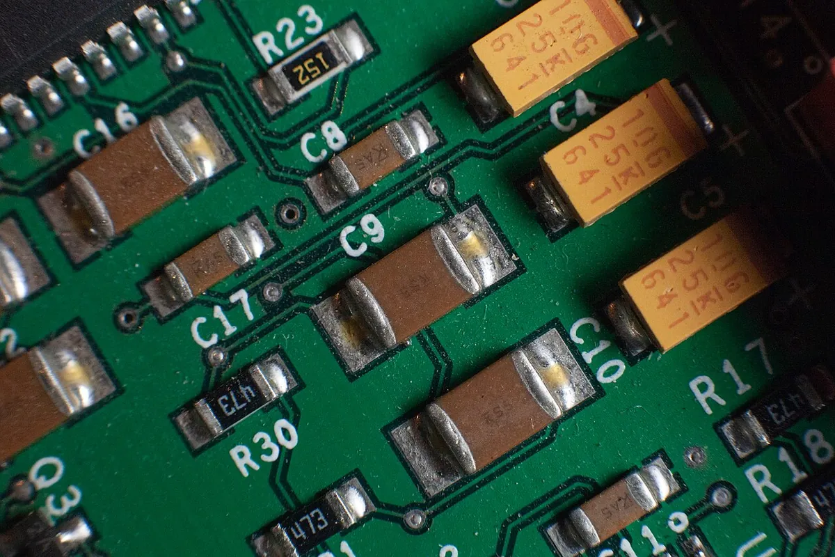
- Small ceramics use a three-digit code in picofarads: two digits then the number of zeros. 104 = 10 × 10⁴ pF = 100 000 pF = 100 nF = 0.1 µF. 103 = 10 nF, 105 = 1 µF, 220 = 22 pF.
- Voltage rating is the most important number on the part. SparkFun warns that exceeding it “will usually result in destroying the capacitor”.
How it works
How it actually works: decoupling, bulk storage and brown-outs
Why the rail dips at all
Every supply has some internal resistance, and every jumper wire, breadboard strip and connector adds a little more. By Ohm’s law (Lesson 2), a current I through that total path resistance R drops a voltage I × R before power reaches the load. Adafruit’s servo driver guide says even micro servos “draw several hundred mA when moving” and some high-torque servos draw “more than 1A each under load”. With 0.5 Ω of path, a 1.5 A gulp costs 0.75 V — a 5 V rail becomes 4.25 V for as long as the gulp lasts.
Why a dip upsets the microcontroller
The ATmega328P datasheet gives a speed grade of 0–20 MHz at 4.5–5.5 V but only 0–10 MHz at 2.7–5.5 V. An Uno runs at 16 MHz, so when its supply sags well below 4.5 V it is outside the comfortable zone and may misbehave. The chip also has a brown-out detector (BOD) that holds it in reset when VCC falls below a set level. Arduino’s own board file programs the Uno’s extended fuse to 0xFD, which selects the BODLEVEL setting the datasheet lists as 2.5–2.9 V (2.7 V typical). So a deep dip causes a clean reset; a smaller one can still cause strange glitches.
Decoupling capacitors: tiny tanks right at the chip
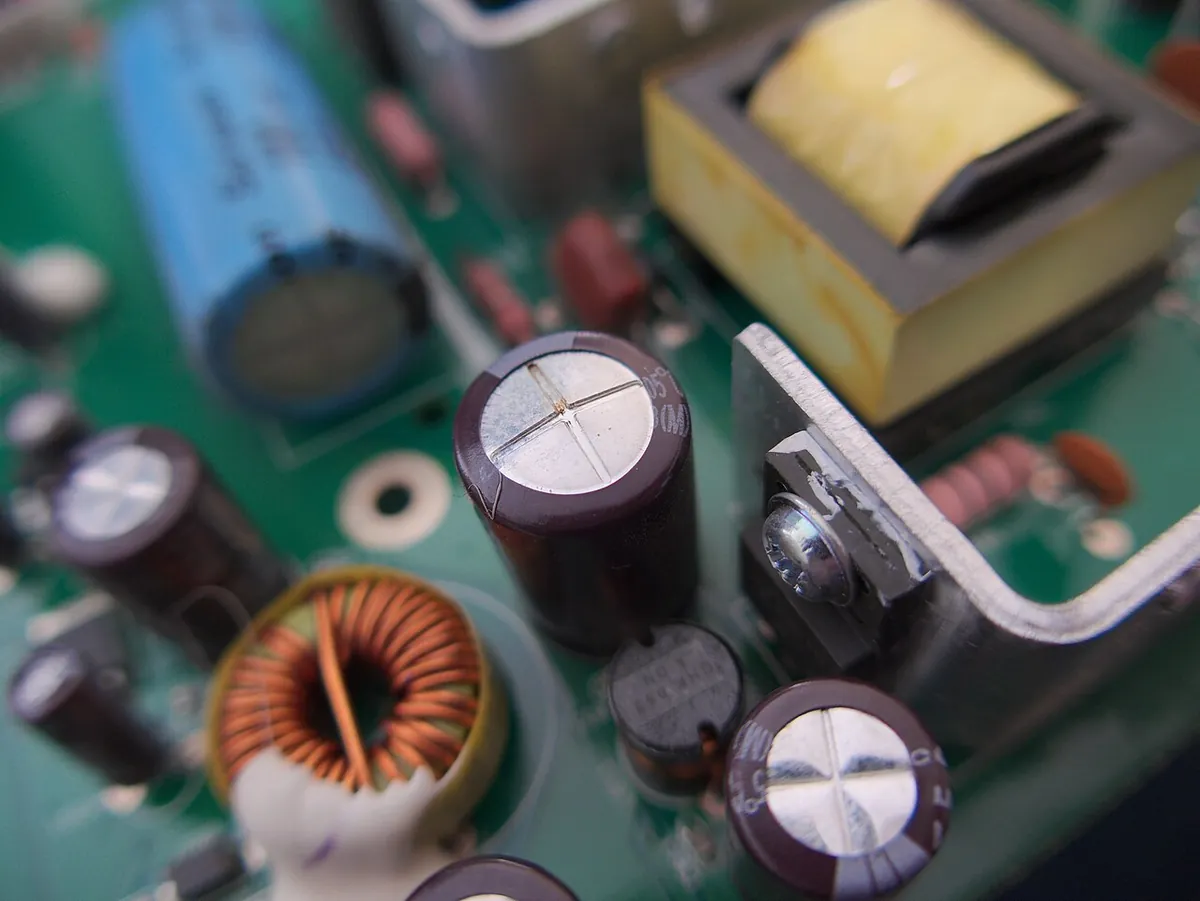
Digital chips draw current in very short, very fast pulses each time they switch. SparkFun describes decoupling (bypass) capacitors as a “very small, local power supply for ICs” that takes out fast ripples, and advises at least one per IC — 0.1 µF is a good choice — placed “as close as possible” to the chip, because the further away they are, the less effective they are. That is why every chip on a good board has a little ceramic capacitor hugging its power pins.
Bulk capacitors: bigger tanks on the motor rail
Servos and motors take bigger gulps that last longer. Here you add a bulk electrolytic of hundreds of µF across the servo power rail, close to the servos. Adafruit’s PCA9685 board even has a spot for one and suggests n × 100 µF (n = number of servos) as a starting point — for example 470 µF or more for 5 servos — while honestly adding that there is “no one magic capacitor value”, because it depends on the servos, the load and the supply.
The honest limit: what a capacitor cannot fix
Use ΔV ≈ I × Δt ÷ C. A 2 A spike lasting 0.2 ms taken entirely from a 1000 µF capacitor would drop it by 2 × 0.0002 ÷ 0.001 = 0.4 V (in practice less, because the supply also helps). But a servo stalled against a hard stop for 60 ms at 1.5 A would need 1.5 × 0.06 ÷ 0.001 = 90 V worth of droop from the same capacitor — impossible. Once the capacitor is drained, the rail sits at Vsupply − I × R, exactly as if it were not there. For long surges you need a supply rated for the stall current, thicker and shorter wires, and a separate servo supply with a common ground.
Decoupling (every chip)
0.1 µF ceramic from VCC to GND at each chip’s power pins. Handles the fastest, smallest spikes.
Local bulk (each servo board / driver)
A few hundred to about a thousand µF electrolytic across the servo V+ and GND near the connectors. Handles servo start-up spikes.
Power path (the real fix for big loads)
A supply rated above the total stall current, short thick wires, a separate servo supply from the logic supply, and one common ground.
Ratings
Reading a real electrolytic datasheet and choosing a safe voltage rating
Let us read the Nichicon UVR series — a standard, widely sold aluminium electrolytic family. The values below are copied from its datasheet.
| Datasheet line | Value | What it means for you |
|---|---|---|
| Rated voltage range | 6.3 to 450 V | Pick the rating per part — the series covers many |
| Category temperature range | −40 to +85 °C (6.3–400 V parts) | Keep it away from hot regulators and motor drivers |
| Capacitance tolerance | ±20 % at 120 Hz, 20 °C | A “1000 µF” part may be anywhere from 800 to 1200 µF |
| Leakage current (6.3–100 V) | ≤ 0.01 CV µA after 2 minutes | 1000 µF × 16 V → at most 160 µA; small but not zero |
| Endurance | 2000 hours at 85 °C, rated voltage | Heat shortens life — cooler is longer |
| Example part | UVR1C102MPD: 1000 µF, 16 V, 10 × 16 mm, 790 mA rms ripple (85 °C, 120 Hz) | A good bulk capacitor for a 5–6 V servo board |
Nichicon’s *Application Guidelines* add the rules that keep you safe: aluminium electrolytics are polarised — make sure no reverse voltage or AC voltage is applied; make sure the peak voltage (DC plus ripple) never exceeds the rated voltage; keep ripple current and temperature within the specification; and note that capacitors used beyond their conditions “may be damaged, catch fire, or vent”. The same guide even mentions servomotor control circuits as places where rapid charging and discharging can happen.
Visual
Visualise it: where stability parts sit in a robot power system
Think “supply → power path → bulk capacitor → servo, plus 0.1 µF at every chip” as you tick each block. Tick the dedicated actuator PSU and the common ground first, then the MCU, driver, actuator, sensor and signal paths until you reach Embedded Robot Ready. Then tick the GPIO-to-motor hazard and read what the checker says. Browser simulation only — it checks the architecture, not real voltages, and never drives hardware.
Interactive · Robot Electronics Wiring Lab
Assemble a full educational architecture: power, common ground, MCU, driver, actuators, sensors, and clean signal paths. Unlock Embedded Robot Ready.
- Missing: Dedicated low-voltage PSU for actuators
- Missing: Common ground MCU ↔ driver ↔ sensors
- Missing: MCU / embedded brain present
- Missing: Motor/servo driver between MCU and actuator
- …+3 more
Low-voltage educational sim · sims ≠ datasheets · never access real hardware from the browser.
Worked example
Worked example: fixing Meera’s resetting arm
Meera’s arm: an Uno-style board, a PCA9685 servo driver and six hobby servos. Arjun and Meera redo the power system step by step with Mrs. Kulkarni.
Step 1: Separate logic power from servo power
- Adafruit is clear: the PCA9685’s VCC pin is “power for the BREAKOUT only, NOT the servo power”. Servos get their own 5–6 V supply on the board’s V+ terminal.
- The Uno stays on USB (or its own regulator). Its pins only send signals — never servo current. (Lesson 4: 40 mA per pin is an absolute maximum.)
- All grounds join: Uno GND, PCA9685 GND and servo-supply (−). Without a common ground the signals have no reference (Lesson 3).
Step 2: Size the supply for the worst case
- Measure (or read from the servo’s datasheet) the stall current. Suppose each servo can pull about 1 A when pushing hard (Adafruit: high-torque servos may exceed 1 A each).
- Six servos rarely stall together, but a shoulder lift can load three at once: plan for at least 3–4 A, and a 5 V, 5 A or larger supply is sensible.
- Use short, thick wires for servo power. Halving the path resistance halves the dip.
Step 3: Add bulk and decoupling capacitors
- Bulk: Adafruit’s starting point is n × 100 µF → 6 × 100 = 600 µF → use a 1000 µF, 16 V electrolytic (e.g. Nichicon UVR1C102MPD) at the PCA9685’s capacitor slot / V+ terminal.
- Voltage check: highest rail ≈ 6.4 V → 1.5 × 6.4 = 9.6 V → 10 V minimum; 16 V gives extra margin.
- Decoupling: the PCA9685 breakout and the Uno already have 0.1 µF parts at their chips. For a home-made board, add one 0.1 µF ceramic at every IC.
- Polarity: stripe (−) to GND, the other lead to V+. Check twice before power-on.
| Item | Before | After | Why |
|---|---|---|---|
| Servo power source | Same pack as the board, thin jumpers | Separate 5 V 5 A supply, short thick leads | Smaller I × R dip |
| Common ground | Missing | Uno GND ↔ PCA9685 GND ↔ supply (−) | Signals need a shared reference |
| Bulk capacitor | None | 1000 µF 16 V at servo V+ | Covers start-up spikes |
| Decoupling | Breakout defaults | 0.1 µF at every IC (already on modules) | Covers fast chip spikes |
| Result | Reset on every shoulder move | Rail stays above 4.5 V in the simulator | Board no longer browns out |
Code lab
Code lab: a capacitor toolkit and a servo-rail simulator in Python
No hardware needed. Both scripts only do arithmetic and print. Copy them into a file on your Linux laptop (from Stage 3) and run them with python3. The outputs below were captured by actually running these exact files.
1. Markings, charge, energy, RC timing and voltage ratings
This script decodes ceramic codes like 104, computes Q = CV and E = ½CV², combines capacitors in parallel and series, prints the RC charging curve (watch for 63.2 % at one τ), works out how long a 1000 µF bulk capacitor takes to discharge through 1 kΩ, picks a voltage rating with 1.5× headroom, and suggests a bulk capacitor for a PCA9685 board from real Nichicon UVR part numbers.
# cap_toolkit.py — capacitor numbers every robot builder needs (Stage 4, Lesson 5)
# Pure arithmetic: it never touches real pins, ports or hardware.
import math

def fmt_cap(c):
    """Show a capacitance in the most readable unit."""
    for unit, scale in (("F", 1), ("uF", 1e-6), ("nF", 1e-9), ("pF", 1e-12)):
        if c >= scale:
            return f"{c / scale:g} {unit}"
    return f"{c:g} F"

# 1) Ceramic markings like "104" = 10 x 10^4 pF
def decode_marking(code):
    return int(code[:2]) * 10 ** int(code[2]) * 1e-12

print("1) Reading ceramic capacitor codes (value in pF)")
for code in ("104", "105", "103", "220"):
    print(f"   {code} -> {fmt_cap(decode_marking(code))}")

# 2) Charge and energy: Q = C*V, E = 1/2 * C * V^2
print("\n2) Charge and energy stored (Q = C x V, E = 1/2 x C x V^2)")
for c, v in ((100e-9, 5.0), (1000e-6, 6.0), (1000e-6, 12.0)):
    q, e = c * v, 0.5 * c * v ** 2
    print(f"   {fmt_cap(c):>8} at {v:4.1f} V -> Q = {q * 1e6:8.2f} uC, E = {e * 1e3:7.3f} mJ")

# 3) Parallel adds, series is product-over-sum
def parallel(*cs):
    return sum(cs)

def series(*cs):
    return 1 / sum(1 / c for c in cs)

print("\n3) Combining capacitors")
print(f"   10 uF + 1 uF + 0.1 uF in parallel = {fmt_cap(parallel(10e-6, 1e-6, 0.1e-6))}")
print(f"   two 10 uF in series              = {fmt_cap(series(10e-6, 10e-6))}")

# 4) RC charging: Vc = V0 * (1 - e^(-t/RC))
R, C, V0 = 10e3, 100e-6, 5.0
tau = R * C
print(f"\n4) Charging 100 uF through 10 kOhm from 5 V (tau = R x C = {tau:.1f} s)")
for n in range(1, 6):
    vc = V0 * (1 - math.exp(-n))
    print(f"   after {n} tau ({n * tau:3.0f} s): {vc:4.2f} V = {100 * vc / V0:5.1f} % charged")

# 5) Safe discharge with a 1 kOhm resistor (as Nichicon's guidelines advise)
def time_to_reach(v_start, v_end, r, c):
    return r * c * math.log(v_start / v_end)

print("\n5) Discharging a 1000 uF bulk cap through 1 kOhm before touching the board")
for v_start in (6.0, 12.0):
    t = time_to_reach(v_start, 0.5, 1e3, 1000e-6)
    print(f"   from {v_start:4.1f} V down to 0.5 V takes {t:4.2f} s (tau = 1 s; waiting 5 tau = 5 s leaves under 1 %)")

# 6) Voltage rating check with headroom (course habit: rating >= 1.5 x the highest rail voltage)
RATINGS = (6.3, 10, 16, 25, 35, 50)

def pick_rating(rail_max, headroom=1.5):
    need = rail_max * headroom
    return next(r for r in RATINGS if r >= need)

print("\n6) Choosing an electrolytic voltage rating (rating >= 1.5 x highest rail voltage)")
for name, vmax in (("5 V logic rail", 5.25), ("6 V servo pack (fresh 4xAA)", 6.4), ("7.4 V 2S Li-ion (full)", 8.4), ("12 V motor rail", 12.6)):
    print(f"   {name:28} max {vmax:5.2f} V -> use a {pick_rating(vmax)} V part")

# 7) Bulk cap for a servo board: Adafruit's starting point is n x 100 uF
UVR_16V = {330: "UVR1C331MPD 8x11.5 mm, ripple 370 mA", 470: "UVR1C471MPD 8x11.5 mm, ripple 440 mA",
           1000: "UVR1C102MPD 10x16 mm, ripple 790 mA", 2200: "UVR1C222MHD 12.5x20 mm, ripple 1300 mA"}
print("\n7) Bulk capacitor for a PCA9685 servo board (start with n x 100 uF)")
for n in (2, 4, 6):
    need = n * 100
    pick = min(v for v in UVR_16V if v >= need)
    print(f"   {n} servos -> at least {need} uF -> Nichicon UVR 16 V {pick} uF ({UVR_16V[pick]})")
Output (run with python3 cap_toolkit.py)
1) Reading ceramic capacitor codes (value in pF)
   104 -> 100 nF
   105 -> 1 uF
   103 -> 10 nF
   220 -> 22 pF

2) Charge and energy stored (Q = C x V, E = 1/2 x C x V^2)
     100 nF at  5.0 V -> Q =     0.50 uC, E =   0.001 mJ
    1000 uF at  6.0 V -> Q =  6000.00 uC, E =  18.000 mJ
    1000 uF at 12.0 V -> Q = 12000.00 uC, E =  72.000 mJ

3) Combining capacitors
   10 uF + 1 uF + 0.1 uF in parallel = 11.1 uF
   two 10 uF in series              = 5 uF

4) Charging 100 uF through 10 kOhm from 5 V (tau = R x C = 1.0 s)
   after 1 tau (  1 s): 3.16 V =  63.2 % charged
   after 2 tau (  2 s): 4.32 V =  86.5 % charged
   after 3 tau (  3 s): 4.75 V =  95.0 % charged
   after 4 tau (  4 s): 4.91 V =  98.2 % charged
   after 5 tau (  5 s): 4.97 V =  99.3 % charged

5) Discharging a 1000 uF bulk cap through 1 kOhm before touching the board
   from  6.0 V down to 0.5 V takes 2.48 s (tau = 1 s; waiting 5 tau = 5 s leaves under 1 %)
   from 12.0 V down to 0.5 V takes 3.18 s (tau = 1 s; waiting 5 tau = 5 s leaves under 1 %)

6) Choosing an electrolytic voltage rating (rating >= 1.5 x highest rail voltage)
   5 V logic rail               max  5.25 V -> use a 10 V part
   6 V servo pack (fresh 4xAA)  max  6.40 V -> use a 10 V part
   7.4 V 2S Li-ion (full)       max  8.40 V -> use a 16 V part
   12 V motor rail              max 12.60 V -> use a 25 V part

7) Bulk capacitor for a PCA9685 servo board (start with n x 100 uF)
   2 servos -> at least 200 uF -> Nichicon UVR 16 V 330 uF (UVR1C331MPD 8x11.5 mm, ripple 370 mA)
   4 servos -> at least 400 uF -> Nichicon UVR 16 V 470 uF (UVR1C471MPD 8x11.5 mm, ripple 440 mA)
6 servos -> at least 600 uF -> Nichicon UVR 16 V 1000 uF (UVR1C102MPD 10x16 mm, ripple 790 mA)2. Simulating a servo rail: spikes vs stalls
This script steps through time one microsecond at a time. A 5 V supply feeds the servo through 0.5 Ω of wires, and an optional bulk capacitor sits at the servo. Case A is a moving servo with short 2 A spikes; case B is a servo stalled for 60 ms. Case C shows what a better power path does. The load numbers are illustrative, not from a datasheet — the lesson is in the pattern.
# servo_rail_sim.py — why a servo rail dips, and what a bulk capacitor can (and cannot) fix
# Stage 4, Lesson 5. A tiny time-step simulation; it never touches real hardware.
#
# Model: an ideal 5.0 V supply -> path resistance R_PATH (supply + wires + connectors)
#        -> the rail node, where an optional bulk capacitor C sits next to the servo load.
# Each step: current from the supply = (V_SUPPLY - v) / R_PATH
#            the capacitor takes (or gives) whatever the load does not use:
#            dv/dt = (i_supply - i_load) / C
# The load numbers below are ILLUSTRATIVE (not from a servo datasheet) — measure your own.

V_SUPPLY = 5.0      # volts
R_PATH = 0.5        # ohms: thin long jumpers + connectors + supply, an honest beginner value
MCU_OK = 4.5        # ATmega328P datasheet: 0-20 MHz needs 4.5-5.5 V
BOD = 2.7           # Arduino Uno fuse setting -> brown-out reset at about 2.7 V (typical)
DT = 1e-6           # 1 microsecond time step

def spiky_load(t):
    """Moving servo: 0.15 A average plus 2.0 A spikes for 0.2 ms every 1 ms."""
    return 0.15 + (2.0 if (t % 1e-3) < 0.2e-3 else 0.0)

def stall_load(t):
    """Servo pushing against a hard stop: 1.5 A for 60 ms, then back to 0.15 A."""
    return 1.5 if 10e-3 <= t < 70e-3 else 0.15

def simulate(load, cap, t_end=0.1):
    v, t, v_min = V_SUPPLY - load(0) * R_PATH, 0.0, V_SUPPLY
    while t < t_end:
        i_load = load(t)
        if cap == 0:
            v = V_SUPPLY - i_load * R_PATH          # no storage: the rail follows the load instantly
        else:
            i_supply = (V_SUPPLY - v) / R_PATH
            v += (i_supply - i_load) / cap * DT
        if t > 5e-3:                                  # ignore the first 5 ms while things settle
            v_min = min(v_min, v)
        t += DT
    return v_min

def verdict(v_min):
    if v_min >= MCU_OK:
        return "OK"
    if v_min >= BOD:
        return "RISK: below 4.5 V, MCU may glitch"
    return "BROWN-OUT RESET"

print(f"Supply {V_SUPPLY} V through {R_PATH} ohm path; MCU comfort line {MCU_OK} V, brown-out {BOD} V\n")
for title, load in (("A) Moving servo with fast 2 A spikes", spiky_load),
                    ("B) Servo stalled for 60 ms at 1.5 A", stall_load)):
    print(title)
    for cap in (0, 100e-6, 470e-6, 1000e-6, 2200e-6):
        v_min = simulate(load, cap)
        label = "no capacitor" if cap == 0 else f"{cap * 1e6:6.0f} uF bulk"
        tau_ms = R_PATH * cap * 1e3
        print(f"   {label:>14}  (R x C = {tau_ms:5.2f} ms)  lowest rail = {v_min:4.2f} V  -> {verdict(v_min)}")
    print()

print("C) Same stall, but with a better power path (thicker, shorter wires: 0.15 ohm)")
R_PATH = 0.15
for cap in (0, 1000e-6):
    v_min = simulate(stall_load, cap)
    label = "no capacitor" if cap == 0 else f"{cap * 1e6:6.0f} uF bulk"
    print(f"   {label:>14}  lowest rail = {v_min:4.2f} V  -> {verdict(v_min)}")
print("\nLesson: capacitors smooth short spikes; long surges need a stronger supply and a better power path.")
Output (run with python3 servo_rail_sim.py)
Supply 5.0 V through 0.5 ohm path; MCU comfort line 4.5 V, brown-out 2.7 V

A) Moving servo with fast 2 A spikes
     no capacitor  (R x C =  0.00 ms)  lowest rail = 3.92 V  -> RISK: below 4.5 V, MCU may glitch
      100 uF bulk  (R x C =  0.05 ms)  lowest rail = 3.94 V  -> RISK: below 4.5 V, MCU may glitch
      470 uF bulk  (R x C =  0.23 ms)  lowest rail = 4.34 V  -> RISK: below 4.5 V, MCU may glitch
     1000 uF bulk  (R x C =  0.50 ms)  lowest rail = 4.54 V  -> OK
     2200 uF bulk  (R x C =  1.10 ms)  lowest rail = 4.64 V  -> OK

B) Servo stalled for 60 ms at 1.5 A
     no capacitor  (R x C =  0.00 ms)  lowest rail = 4.25 V  -> RISK: below 4.5 V, MCU may glitch
      100 uF bulk  (R x C =  0.05 ms)  lowest rail = 4.25 V  -> RISK: below 4.5 V, MCU may glitch
      470 uF bulk  (R x C =  0.23 ms)  lowest rail = 4.25 V  -> RISK: below 4.5 V, MCU may glitch
     1000 uF bulk  (R x C =  0.50 ms)  lowest rail = 4.25 V  -> RISK: below 4.5 V, MCU may glitch
     2200 uF bulk  (R x C =  1.10 ms)  lowest rail = 4.25 V  -> RISK: below 4.5 V, MCU may glitch

C) Same stall, but with a better power path (thicker, shorter wires: 0.15 ohm)
     no capacitor  lowest rail = 4.78 V  -> OK
     1000 uF bulk  lowest rail = 4.78 V  -> OK

Lesson: capacitors smooth short spikes; long surges need a stronger supply and a better power path.Real world
Where capacitors keep real robots alive
- Servo driver boards: PCA9685 breakouts provide a spot for a bulk electrolytic on the servo V+ rail (Adafruit suggests about 100 µF per servo as a start).
- Every microcontroller board: Arduino, ESP32 and STM32 boards carry 0.1 µF ceramics beside the chip power pins — look for the tiny beige chips near the processor.
- Voltage regulators: linear regulators and buck converters need input and output capacitors to stay stable; their datasheets specify them.
- Power adapters and chargers: SparkFun’s teardown of a 9 V wall adapter found four electrolytics from 47 µF to 1000 µF smoothing the output — never open one yourself.
- Drones and RC cars: look at a speed controller and you will usually find electrolytic capacitors across its battery input, doing the same bulk job for the motor’s current spikes.
- Camera flash and defibrillators: capacitors charged slowly and dumped quickly (OpenStax) — the same “fast release” property that steadies a servo rail.
On the bench
On a real bench: a servo rail with a bulk capacitor and a voltage logger
When you have an Uno-style board, one hobby servo, a 5–6 V supply (adapter or 4×AA pack), a 470–1000 µF 16 V electrolytic, a 0.1 µF ceramic and two 10 kΩ resistors, build this in order. The sketch is for a real board and is not run inside the browser.
Power off while wiring
Unplug USB and the servo supply before adding or moving any wire. Wire, check, then power.
Servo power — never from the Arduino
Servo red → servo supply (+). Servo brown/black → supply (−). Servo signal (orange/yellow) → D9. Never feed the servo from a GPIO pin or the Uno’s 5V header.
Common ground
One wire from servo-supply (−) to Uno GND. Without it, the D9 signal has no reference.
Bulk capacitor at the servo
Electrolytic across servo V+ and GND, as close to the servo connector as you can. Stripe (−) to GND. Add the 0.1 µF ceramic in parallel (either way round).
Voltage divider to A0
Servo V+ → 10 kΩ → A0 → 10 kΩ → GND. This halves the rail so A0 never sees more than 5 V.
Power and log
Plug in USB, upload
rail_logger.ino, open the Serial Monitor at 9600 baud, then switch on the servo supply. Note the lowest rail voltage. Power off, discharge, remove the bulk capacitor and repeat. Compare.
// rail_logger.ino — sweep one servo and log the lowest servo-rail voltage (Stage 4, Lesson 5)
// For a REAL board on your bench. This sketch is not run inside the browser.
// Power:  servo red wire -> external 5-6 V supply (+); servo brown/black wire -> supply (-).
//         Supply (-) -> Arduino GND (common ground). NEVER power the servo from an Arduino pin or its 5V pin.
// Bulk:   470-1000 uF, 16 V electrolytic right at the servo connector, stripe (-) side to GND.
// Sense:  servo rail (+) -> 10 kOhm -> A0 -> 10 kOhm -> GND  (halves the voltage, keeps A0 below 5 V)
#include <Servo.h>

const int SERVO_PIN = 9;
const int SENSE_PIN = A0;
const float VREF = 5.0;      // the Uno's ADC reference is its own 5 V — measure yours and edit this
const float DIVIDER = 2.0;   // two equal 10 kOhm resistors

Servo joint;

float readRail() {
  int raw = analogRead(SENSE_PIN);          // 0..1023
  return raw * VREF / 1023.0 * DIVIDER;
}

float lowestDuringMove(int angle, unsigned long ms) {
  float lowest = 99.0;
  joint.write(angle);
  unsigned long start = millis();
  while (millis() - start < ms) {           // keep sampling while the servo travels
    float v = readRail();
    if (v < lowest) lowest = v;
  }
  return lowest;
}

void setup() {
  Serial.begin(9600);
  joint.attach(SERVO_PIN);
  joint.write(90);
  delay(1000);
}

void loop() {
  float a = lowestDuringMove(30, 800);
  float b = lowestDuringMove(150, 800);
  Serial.print("lowest servo rail while moving: ");
  Serial.print(min(a, b), 2);
  Serial.println(" V");
}| Check | Meter mode | Power | What you expect |
|---|---|---|---|
| Capacitor polarity | Look, then look again | OFF | Stripe (−) side on the GND rail |
| Supply voltage | DC volts | ON, servo idle | Close to the adapter/pack value (e.g. 5.0–6.4 V) |
| Rail at the servo while moving | DC volts (or the logger) | ON | A small dip; with the bulk capacitor it should dip less |
| A0 reading | Serial Monitor | ON | About half the rail voltage × 2 = rail (check against your meter) |
| Capacitor after switch-off | DC volts | OFF | Falls towards 0 V; discharge with 1 kΩ before touching |
Mistakes
Common mistakes and confusions
Debugging
Debugging: when it doesn’t work
| Symptom | Likely cause | Fix |
|---|---|---|
| MCU resets when servos start moving | Supply sags under servo inrush / stall current | Bigger supply, bulk capacitor near the servo rail, separate logic supply |
| Servos jitter at rest | Noisy rail or missing decoupling near the driver | Add 100 µF bulk + 100 nF ceramic close to the driver |
| Electrolytic cap gets warm or bulges | Wrong polarity or voltage rating too low | Power off, replace it; stripe (−) to GND; rating ≥ 1.5–2× rail |
| Reading on the rail looks fine but the robot still resets | Meter is too slow to see the dip | Log the minimum with rail_logger.ino or a scope |
Think
Think about it
Think
Arjun says: “Easy fix — I’ll just put a 10 000 µF capacitor on the battery and keep the thin jumper wires.” Meera’s arm then works when it waves, but still resets when the shoulder lifts a 500 g load for two seconds. Using ΔV ≈ I × Δt ÷ C and Ohm’s law, explain why, and what Arjun should change.
Experiment
Try it in the lab: plan a stable power system
Twenty minutes with the Robot Electronics Wiring Lab, the two Python scripts and your notebook. You will build a safe architecture, then mark exactly where each capacitor goes and prove with numbers why.
Experiment
Power stability plan
You will need
- Robot Electronics Wiring Lab (below, runs in your browser)
- Notebook or a text file
- Optional: your Linux laptop to run `cap_toolkit.py` and `servo_rail_sim.py`
Steps
- In the lab, tick **Dedicated low-voltage PSU for actuators** and **Common ground**. In your notebook write the servo supply voltage you would use (5–6 V) and its current rating (above the total stall current).
- Tick the MCU, driver, actuator, sensor and signal blocks until the lab shows **Embedded Robot Ready**. Draw the same blocks on paper.
- On your drawing, mark a **0.1 µF ceramic** at the MCU and at the driver chip, and a **bulk electrolytic** at the driver’s servo V+ terminal. Write the value (n × 100 µF, rounded up) and the voltage rating (≥ 1.5 × highest rail).
- Tick the **GPIO wired straight to motor** hazard. Read the warning, untick it, and write one sentence on why this also wrecks power stability.
- Run `servo_rail_sim.py`. Copy the lowest rail voltage for no capacitor, 470 µF and 1000 µF in case A, and for case B. Circle which case a capacitor fixes.
- Change `R_PATH` to 0.25 and run again. Write which helps the stall case more: doubling the capacitor or halving the path resistance.
Interactive · Robot Electronics Wiring Lab
Assemble a full educational architecture: power, common ground, MCU, driver, actuators, sensors, and clean signal paths. Unlock Embedded Robot Ready.
- Missing: Dedicated low-voltage PSU for actuators
- Missing: Common ground MCU ↔ driver ↔ sensors
- Missing: MCU / embedded brain present
- Missing: Motor/servo driver between MCU and actuator
- …+3 more
Low-voltage educational sim · sims ≠ datasheets · never access real hardware from the browser.
A stable robot needs both: a strong power path for long surges and capacitors placed close to the loads for short spikes. The lab checks the architecture; the scripts show the numbers; the datasheet gives the ratings.
Knowledge check
Check your understanding
Knowledge check
1. Decoupling capacitors mainly…
2. A servo stalls and pulls 1.5 A for two seconds. What must handle that?
3. Aluminium electrolytic capacitors…
4. A ceramic capacitor is marked 104. Its value is…
5. A capacitor charges through a resistor. After one time constant (τ = RC) it reaches about…
6. Which voltage rating is a sensible choice for a bulk capacitor on a 6 V servo battery pack?
7. Where should the bulk capacitor for six servos on a PCA9685 board go?
8. How much energy does a 1000 µF capacitor store at 6 V?
9. Why might an Uno glitch even before its 2.7 V brown-out reset triggers?
10. You have just switched off a servo board with a 1000 µF capacitor. What is the safe next step?
Mini assignment
Hands-on assignment
Mini assignment
Power stability report for your robot
Design and justify the power system of a small servo robot — supply, power path, bulk and decoupling capacitors — with numbers from real datasheets and from this chapter’s scripts.
Deliverables
- A block diagram: logic supply, servo supply, PCA9685 (or driver), servos, MCU, common ground. Mark every capacitor with its value, type, voltage rating and polarity.
- A power budget table: idle, moving and stall current for each servo (from the datasheet or your own measurement), and the supply rating you chose.
- Bulk capacitor choice: n × 100 µF starting point, the real part number you would buy (for example from the Nichicon UVR table), its voltage rating with headroom and its ripple rating.
- Output of `cap_toolkit.py` and `servo_rail_sim.py` with at least one change each (from the Play with it and Debugging tips), with one sentence on what changed and why.
- A safety checklist: polarity, rating, placement, discharge before touching, no servo power from GPIO.
- Half a page in your own words: “bulk vs decoupling vs just buy a bigger power supply” — when each one is the right answer.
Do this, step by step
- Draw your power block diagram: logic supply, servo supply, driver, servos, MCU, common ground. Mark each capacitor’s value, type, rating and polarity.
- Fill a power budget table (idle, moving, stall per servo) and pick a supply with headroom.
- Choose a real bulk capacitor part (value, voltage rating, ripple rating).
- Run
cap_toolkit.pyandservo_rail_sim.pywith one change each; paste outputs. - Write the safety checklist (polarity, rating, placement, discharge, no servo power from GPIO).
Stuck? Hints, one at a time
- Hint 1: Stall current is the number that resets robots — use it, not the idle number, to size the supply.
- Hint 2: A common starting point in the lesson is about 100 µF of bulk capacitance per servo on the servo rail, plus 100 nF ceramic next to each chip.
- Hint 3: For voltage rating, give headroom: a 6 V servo rail → a 10 V or 16 V electrolytic.
- Hint 4: In
servo_rail_sim.py, raise the capacitance and watch the minimum rail voltage rise — then change the stall current and see which matters more.
Challenges (pick by level)
- 🟢 Easy: Decode the ceramic codes 223, 474 and 101. Which one is a typical decoupling value?
- 🟢 Easy: Two 470 µF capacitors in parallel, then in series. What totals do you get, and which arrangement doubles the voltage rating?
- 🟡 Medium: A 220 µF capacitor charges through 4.7 kΩ from 5 V. Compute τ and the time to reach 4.5 V. Check it with a small change to
cap_toolkit.py. - 🟡 Medium: Choose a voltage rating and a Nichicon UVR part for a 3S Li-ion pack (12.6 V full).
- 🟠 Hard-ish: In
servo_rail_sim.py, add awave_loadwith 1 A pulses lasting 2 ms every 20 ms. Find the smallest standard capacitor that keeps the rail above 4.5 V. - 🔴 Hard: Add a simple ESR (series resistance) to the capacitor in the simulator — the capacitor current also drops voltage across ESR. Compare 0.01 Ω and 0.5 Ω. Why do low-ESR capacitors matter near motors?
- ⚫ Expert: On a real bench, use
rail_logger.inoto log the lowest rail with no capacitor, 470 µF and 1000 µF (power off and discharge between changes). Plot the results and explain any difference from the simulator.
Next step
Your robot’s power is now steady. In Lesson 6 — Diodes, MOSFETs & Electronic Switching you will learn how a tiny GPIO signal can safely switch a big motor current, and why a diode is needed when a motor or relay coil switches off.
Tip: explain today’s chapter with the water-tank picture. If you can say “the supply is the pipeline, the wires are the long pipe, the capacitor is the overhead tank near the tap” — and then size a 1000 µF, 16 V bulk capacitor for six servos and explain why it still cannot fix a stall — you have understood power stability.
Look back: Lesson 4: Resistors, LEDs & Basic Components. Next: Lesson 6: Diodes, MOSFETs & Electronic Switching. Related: Stage 0 — Power & Communication and Stage 6 — 6DOF Arm.
Sources
- SparkFun Learn: Capacitors — construction, Q = CV, I = C dV/dt, ceramic vs electrolytic, polarity, decoupling, derating.
- Nichicon UVR series aluminium electrolytic capacitor datasheet — tolerance, temperature range, leakage, endurance, UVR1C102MPD ratings.
- Nichicon: Application Guidelines for Aluminum Electrolytic Capacitors — polarity, no reverse/AC voltage, peak voltage, discharge through 1 kΩ.
- Murata Capacitors FAQ: capacitance change with DC voltage — DC bias in X5R/X7R vs C0G ceramics.
- OpenStax University Physics Vol. 2, 10.5 RC Circuits — τ = RC, 63.2 % after one time constant.
- OpenStax University Physics Vol. 2, 8.3 Energy Stored in a Capacitor — U = ½CV².
- Adafruit PCA9685 16-Channel Servo Driver: Hooking it Up — VCC is logic only, servo current, n × 100 µF bulk capacitor.
- Microchip ATmega48A/PA/88A/PA/168A/PA/328/P datasheet — speed grades vs supply voltage, brown-out levels.
- Arduino AVR core boards.txt — Uno extended fuse 0xFD (brown-out level).
- Photos: Wikimedia Commons (credits under each image).
Self-attested for now — keep artifacts in your lab notebook.
Complete
Today's goal
0 of 1 done today
Mark this lesson complete when you have worked the experiment, knowledge check, and assignment (even roughly).