
Electronics & Embedded Systems · Lesson 07
Digital Signals & GPIO
Est. 45–60 min
Why
Why your robot needs to know exactly when a wire is HIGH
Every robot is full of yes/no questions: Is the gripper closed? Did the joint hit its limit? Is the stop button pressed? Should the motor driver be enabled? Is the LED on? A microcontroller answers them with GPIO — general-purpose input/output pins. In Lesson 4 you met the push button and the pull-up resistor; in Lesson 6 you used a pin to drive a MOSFET. This chapter looks at the pin itself: what voltages it accepts as HIGH and LOW, how much it can safely give, how two boards with different voltages can talk, and how to turn changing pin readings into reliable robot events.
By the end you will be able to: explain the three pin modes (INPUT, INPUT_PULLUP, OUTPUT), read the HIGH/LOW thresholds from the ATmega328P datasheet, calculate noise margins, connect a 3.3 V board and a 5 V board safely, choose a series resistor for an LED, detect rising and falling edges in code, build a latching stop with active-LOW switches, and explain why a GPIO pin must never power a motor or servo.
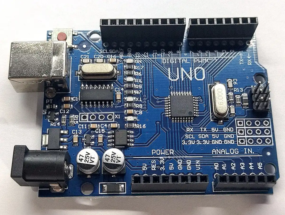
pinMode().Photo: JrawX · CC0 1.0 · Source: Wikimedia Commons · resized, converted to WebPConcept
Digital signals and GPIO pins in plain words
Think of a railway signal at an Indian station. The driver doesn’t care if the lamp is a little dim or a little bright — it is either red or green. If the lamp were somewhere in between, a careful driver would stop and ask. A digital pin is the same: it only wants HIGH or LOW, and there is a grey zone in the middle where the answer is not guaranteed. Good robot wiring keeps every signal far away from that grey zone.
Three modes of a GPIO pin
| Mode | What the pin does | Typical robot use |
|---|---|---|
| INPUT | High-impedance: it only listens. Arduino describes it as like a 100 MΩ resistor in front of the pin, so it draws almost nothing — and floats if nothing drives it. | Sensor outputs that actively drive HIGH and LOW |
| INPUT_PULLUP | Listens, with a built-in pull-up resistor to VCC (20–50 kΩ on the ATmega328P). Unpressed reads HIGH, pressed-to-GND reads LOW. | Buttons, limit switches, stop buttons |
| OUTPUT | Drives the pin to VCC (HIGH) or 0 V (LOW). Can source or sink current, up to the absolute maximum of 40 mA. | LEDs with resistors, driver ENABLE/DIR inputs, MOSFET gates |
Arduino’s Digital Pins guide also reminds us that pins default to inputs at power-up, and that the analog pins A0–A5 can be used as digital pins too. If you call digitalWrite(pin, HIGH) without setting OUTPUT, the digitalWrite() reference warns that you are only turning on the internal pull-up — an LED on that pin will glow dimly. That is a very common beginner bug.
What counts as HIGH and LOW
The ATmega328P datasheet (the chip on the Uno R3) gives the input thresholds as fractions of its supply VCC: an input is guaranteed LOW below 0.3 × VCC and guaranteed HIGH above 0.6 × VCC. At 5 V that is LOW below 1.5 V and HIGH above 3.0 V. SparkFun’s logic-levels tutorial calls the gap in between the invalid region — on an Arduino it is 1.5 V to 3.0 V. Meera’s 2 V wire sat right in it.
LOW ≤ 0.3 × VCC HIGH ≥ 0.6 × VCC
- VCC = 5 V → LOW ≤ 1.5 V, HIGH ≥ 3.0 V
- VCC = 3.3 V → LOW ≤ 0.99 V, HIGH ≥ 1.98 V
- Between the two lines the chip may read either value — never design for that zone
The inputs also have a small built-in Schmitt trigger with hysteresis (the datasheet shows about 0.05 × VCC), so a slowly changing voltage doesn’t make the input flicker right at the threshold. It helps, but it does not rescue a floating pin.
What an OUTPUT pin really gives
A pin set HIGH is not a perfect 5 V source. The ATmega328P datasheet promises at least 4.2 V while sourcing 20 mA, and at most 0.9 V while sinking 20 mA (VCC = 5 V). The more current you pull, the more the voltage sags. The absolute maximum is 40 mA per pin and 200 mA through the chip’s VCC and GND pins altogether — absolute maximum means “damage may happen here”, not “safe to use”. Arduino’s guide says 40 mA is enough for an LED with its resistor, but not enough for most relays, solenoids or motors.
| Quantity | Value | Source |
|---|---|---|
| Input LOW guaranteed | ≤ 0.3 × VCC (1.5 V) | ATmega328P datasheet |
| Input HIGH guaranteed | ≥ 0.6 × VCC (3.0 V) | ATmega328P datasheet |
| Output HIGH at 20 mA | ≥ 4.2 V | ATmega328P datasheet |
| Output LOW at 20 mA | ≤ 0.9 V | ATmega328P datasheet |
| Internal pull-up | 20–50 kΩ | ATmega328P datasheet |
| Absolute max per pin | 40 mA | ATmega328P datasheet |
| Absolute max VCC/GND pins | 200 mA total | ATmega328P datasheet |
| Pin voltage absolute max | −0.5 V to VCC + 0.5 V | ATmega328P datasheet |
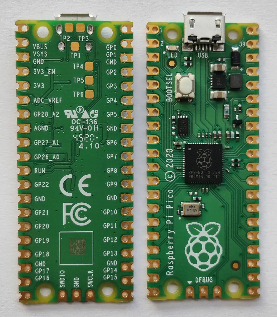
3.3 V and 5 V boards talking to each other
SparkFun’s rule of thumb: a 3.3 V output can usually drive a 5 V input, because 3.3 V is above the 5 V Uno’s 3.0 V HIGH threshold — but only just. The opposite direction is dangerous: a 5 V output into a 3.3 V-only input can permanently damage some chips (SparkFun warns that on certain 3.3 V devices anything above 3.6 V does). Knock the signal down with a voltage divider such as 1 kΩ and 2 kΩ, or use a logic-level shifter board. Some chips have 5 V-tolerant pins; trust only the datasheet for that.
How it works
How it actually works: noise margins, active-LOW and edges
Noise margin: the safety gap of a signal
Long wires next to motors pick up electrical noise. The noise margin is how many volts of noise a signal can tolerate before the receiver might misread it. For a HIGH it is (sender’s minimum HIGH output) − (receiver’s minimum HIGH input). For an Uno driving another Uno: 4.2 V − 3.0 V = 1.2 V of margin. For a 3.3 V board driving an Uno: about 3.3 V − 3.0 V = 0.3 V. It works on a short wire; it is fragile along a buzzing robot arm.
NM(high) = VOH(min) − VIH(min) NM(low) = VIL(max) − VOL(max)
- VOH = output HIGH voltage of the sender, VIH = input HIGH threshold of the receiver
- VOL = output LOW voltage of the sender, VIL = input LOW threshold of the receiver
- Bigger margin = more noise the wire can pick up before a bit flips
Active-LOW: why robots like switches to ground
With INPUT_PULLUP, an untouched switch reads HIGH and a pressed switch reads LOW. This is called active-LOW logic. Arduino’s guide points out the inverted logic; robots use it a lot because the switch only needs a wire to ground, the pull-up is free, and a broken wire to the switch reads HIGH — which you can design to mean “not safe, stop”.
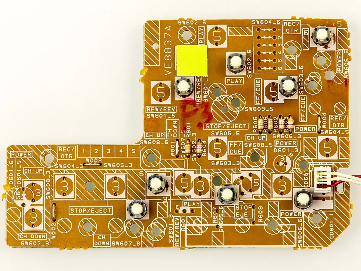
Levels and edges
A level is what the pin is right now (HIGH or LOW). An edge is the moment it changes: falling (HIGH → LOW) or rising (LOW → HIGH). Robots need both. “Is the limit switch pressed?” is a level — check it every loop and keep the motor off while it is LOW. “How many times has the gripper button been pressed?” is an edge — count it once, when the reading changes. To find an edge, remember the previous reading and compare. Lesson 4’s debounce idea still applies to mechanical switches.
Read
int now = digitalRead(pin);once per loop.Compare
if (last == HIGH && now == LOW)→ falling edge (pressed, for an active-LOW switch).Remember
last = now;at the end, ready for the next loop.Act on levels for safety
Motor enable = not stopped AND limit not pressed — checked every loop, not just on edges.
Safe pins
A safe pin plan: what may and may not touch a GPIO pin
| Connection | Safe on a GPIO pin? | Do this instead / note |
|---|---|---|
| LED | Yes, with a series resistor | 220 Ω–1 kΩ at 5 V (see the script) |
| Button / limit switch to GND | Yes | INPUT_PULLUP; active-LOW |
| Sensor digital output (same voltage) | Yes | INPUT; check the sensor’s supply matches the board |
| 5 V signal into a 3.3 V board | Not directly | Divider (1 kΩ / 2 kΩ) or a level shifter |
| MOSFET gate / driver ENABLE or DIR input | Yes — it’s a signal | Gate resistor and pull-down (Lesson 6) |
| Servo signal wire | Yes — signal only | Servo power from a separate supply, common ground |
| DC motor, relay coil, solenoid | NEVER | MOSFET or driver, separate supply, flyback diode |
| Servo power (red wire) | NEVER | Separate 5–6 V supply sized for stall current |
Visual
Visualise it: one pin as input, output and PWM
Toggle **D7** and watch the status line change between HIGH and LOW — the note reminds you that a digital output is good for LEDs and logic, not motors. The lab labels HIGH as 3.3 V to remind you that many modern boards run at 3.3 V; an Uno R3’s HIGH is 5 V. The A0 slider and D9 PWM duty belong to Lessons 8 and 9; peek at them now. Browser simulation only — no real pins are touched.
Interactive · GPIO / ADC / PWM Lab
Fake MCU board for digital out, analog in, and PWM duty. Browser-only — never talks to real USB/serial/hardware.
GPIO D7
Good for LEDs / logic — not motors.
ADC A0 (10-bit)
raw 512 → 2.50 V
Pot / distance proxy → robot perception.
PWM D9
duty 40%
PWM → driver → motor — never GPIO-direct.
board@sim ~ pins: D7=0 A0=512 D9=40% · educational MCU only
Code lab
Code lab: thresholds, safe level shifting and robot events in Python
1. Logic levels, noise margins, dividers and LED resistors
This script computes the ATmega328P thresholds at 5 V and 3.3 V, classifies voltages, compares noise margins for two links, checks divider choices for a 5 V → 3.3 V signal, and prints LED currents for common resistors.
# logic_levels.py — what voltage counts as HIGH or LOW, and can two boards talk safely?
# Stage 4, Lesson 7. Simulation only: arithmetic and prints. No pins, no ports, no hardware.

def avr_input(vcc):
    """ATmega328P input thresholds (datasheet): LOW below 0.3 x VCC, HIGH above 0.6 x VCC."""
    return 0.3 * vcc, 0.6 * vcc


def read_as(v, vil_max, vih_min):
    if v <= vil_max:
        return "LOW"
    if v >= vih_min:
        return "HIGH"
    return "?? undefined zone"


print("1) ATmega328P input thresholds at two supply voltages")
print("-" * 70)
for vcc in (5.0, 3.3):
    lo, hi = avr_input(vcc)
    print(f"  VCC {vcc:.1f} V: LOW if <= {lo:.2f} V, HIGH if >= {hi:.2f} V, between = undefined")

print()
print("2) Classify some voltages on a 5 V Uno input pin")
print("-" * 70)
lo, hi = avr_input(5.0)
for v in (0.0, 0.4, 1.2, 1.8, 2.5, 2.9, 3.3, 4.2, 5.0):
    print(f"  {v:3.1f} V -> {read_as(v, lo, hi)}")

print()
print("3) Noise margin = how much junk a wire can pick up before a bit flips")
print("-" * 70)
links = [
    # (name, VOH_min of sender, VOL_max of sender, VIH_min of receiver, VIL_max of receiver)
    ("5 V Uno -> 5 V Uno", 4.2, 0.9, 3.0, 1.5),
    ("3.3 V board -> 5 V Uno", 3.3, 0.0, 3.0, 1.5),   # ideal 3.3 V output, no load
]
for name, voh, vol, vih, vil in links:
    nm_h, nm_l = voh - vih, vil - vol
    print(f"  {name:<24} high margin {nm_h:4.2f} V, low margin {nm_l:4.2f} V")
print("  The 3.3 V -> 5 V link works, but with only ~0.3 V of HIGH margin. Short wires!")

print()
print("4) 5 V signal into a 3.3 V-only pin: divide it down first")
print("-" * 70)
for r1, r2 in ((1_000, 2_000), (10_000, 20_000), (2_200, 3_300), (1_000, 10_000)):
    v_out = 5.0 * r2 / (r1 + r2)
    flag = "OK for a 3.3 V pin" if v_out <= 3.4 else "TOO HIGH: will hurt a 3.3 V-only pin"
    print(f"  R1 {r1/1000:4.1f} k (top), R2 {r2/1000:4.1f} k (bottom) -> {v_out:4.2f} V  {flag}")
print("  Dividers are fine for slow one-way signals; fast or two-way buses need a level shifter.")

print()
print("5) OUTPUT pin: series resistor for an LED (Uno at 5 V)")
print("-" * 70)
for led, vf in (("red", 2.0), ("green", 2.2), ("blue/white", 3.0)):
    for r in (220, 470, 1000):
        i_ma = (5.0 - vf) / r * 1000
        print(f"  {led:<10} VF {vf:.1f} V, R {r:4d} ohm -> {i_ma:5.1f} mA")
Output (run with python3 logic_levels.py)
1) ATmega328P input thresholds at two supply voltages
----------------------------------------------------------------------
  VCC 5.0 V: LOW if <= 1.50 V, HIGH if >= 3.00 V, between = undefined
  VCC 3.3 V: LOW if <= 0.99 V, HIGH if >= 1.98 V, between = undefined

2) Classify some voltages on a 5 V Uno input pin
----------------------------------------------------------------------
  0.0 V -> LOW
  0.4 V -> LOW
  1.2 V -> LOW
  1.8 V -> ?? undefined zone
  2.5 V -> ?? undefined zone
  2.9 V -> ?? undefined zone
  3.3 V -> HIGH
  4.2 V -> HIGH
  5.0 V -> HIGH

3) Noise margin = how much junk a wire can pick up before a bit flips
----------------------------------------------------------------------
  5 V Uno -> 5 V Uno       high margin 1.20 V, low margin 0.60 V
  3.3 V board -> 5 V Uno   high margin 0.30 V, low margin 1.50 V
  The 3.3 V -> 5 V link works, but with only ~0.3 V of HIGH margin. Short wires!

4) 5 V signal into a 3.3 V-only pin: divide it down first
----------------------------------------------------------------------
  R1  1.0 k (top), R2  2.0 k (bottom) -> 3.33 V  OK for a 3.3 V pin
  R1 10.0 k (top), R2 20.0 k (bottom) -> 3.33 V  OK for a 3.3 V pin
  R1  2.2 k (top), R2  3.3 k (bottom) -> 3.00 V  OK for a 3.3 V pin
  R1  1.0 k (top), R2 10.0 k (bottom) -> 4.55 V  TOO HIGH: will hurt a 3.3 V-only pin
  Dividers are fine for slow one-way signals; fast or two-way buses need a level shifter.

5) OUTPUT pin: series resistor for an LED (Uno at 5 V)
----------------------------------------------------------------------
  red        VF 2.0 V, R  220 ohm ->  13.6 mA
  red        VF 2.0 V, R  470 ohm ->   6.4 mA
  red        VF 2.0 V, R 1000 ohm ->   3.0 mA
  green      VF 2.2 V, R  220 ohm ->  12.7 mA
  green      VF 2.2 V, R  470 ohm ->   6.0 mA
  green      VF 2.2 V, R 1000 ohm ->   2.8 mA
  blue/white VF 3.0 V, R  220 ohm ->   9.1 mA
  blue/white VF 3.0 V, R  470 ohm ->   4.3 mA
  blue/white VF 3.0 V, R 1000 ohm ->   2.0 mA
2. From readings to robot events
This script plays back a list of fake readings — one per pass of loop() — for an active-LOW limit switch, a stop button and a reset button. It prints the edges it finds, latches the stop, and shows when the motor-driver ENABLE line would be ON. The same logic is in the Arduino sketch further down.
# gpio_events.py — turn raw pin readings into robot events: edges, active-LOW switches, a latched e-stop.
# Stage 4, Lesson 7. Simulation only: a list of fake readings, one per loop pass. No hardware.

# A limit switch wired with INPUT_PULLUP: 1 = not touched, 0 = touched (active LOW).
limit = [1, 1, 1, 0, 0, 0, 0, 1, 1, 1, 0, 0, 1, 1, 1, 1]
# An e-stop button, also INPUT_PULLUP: pressed once at pass 5, released at pass 7.
estop = [1, 1, 1, 1, 1, 0, 0, 1, 1, 1, 1, 1, 1, 1, 1, 1]
# Operator presses RESET at pass 12 (active LOW too).
reset = [1] * 12 + [0] + [1] * 3

print("pass | limit estop reset | event                                       | motor enable")
print("-" * 90)
prev_limit = 1
latched = False
for n, (lim, es, rs) in enumerate(zip(limit, estop, reset)):
    events = []
    if prev_limit == 1 and lim == 0:
        events.append("FALLING edge: joint hit limit")
    if prev_limit == 0 and lim == 1:
        events.append("RISING edge: left the limit")
    prev_limit = lim
    if es == 0 and not latched:
        latched = True
        events.append("E-STOP latched")
    if rs == 0 and latched and es == 1:
        latched = False
        events.append("reset accepted")
    enable = (not latched) and lim == 1
    print(f" {n:3d} |   {lim}     {es}     {rs}   | {', '.join(events) or '-':<43} | "
          f"{'ON ' if enable else 'OFF'}")

print()
print("Notes:")
print("  * The e-stop stays latched after the button is released, until RESET.")
print("  * Edges happen once; levels last. Count edges, act on levels.")
Output (run with python3 gpio_events.py)
pass | limit estop reset | event                                       | motor enable
------------------------------------------------------------------------------------------
   0 |   1     1     1   | -                                           | ON
   1 |   1     1     1   | -                                           | ON
   2 |   1     1     1   | -                                           | ON
   3 |   0     1     1   | FALLING edge: joint hit limit               | OFF
   4 |   0     1     1   | -                                           | OFF
   5 |   0     0     1   | E-STOP latched                              | OFF
   6 |   0     0     1   | -                                           | OFF
   7 |   1     1     1   | RISING edge: left the limit                 | OFF
   8 |   1     1     1   | -                                           | OFF
   9 |   1     1     1   | -                                           | OFF
  10 |   0     1     1   | FALLING edge: joint hit limit               | OFF
  11 |   0     1     1   | -                                           | OFF
  12 |   1     1     0   | RISING edge: left the limit, reset accepted | ON
  13 |   1     1     1   | -                                           | ON
  14 |   1     1     1   | -                                           | ON
  15 |   1     1     1   | -                                           | ON

Notes:
  * The e-stop stays latched after the button is released, until RESET.
  * Edges happen once; levels last. Count edges, act on levels.
Real world
Where GPIO pins run real robots
- Limit and home switches: 3D printers, CNC machines and robot arms use switches on GPIO inputs to find their starting position and to stop before a crash.
- Motor-driver control lines: ENABLE, DIR and STEP inputs on driver boards are GPIO outputs from the microcontroller — signals only, never power.
- Status LEDs: every board’s “power”, “TX/RX” or “error” LED is a GPIO output with a resistor.
- Bumpers and line sensors: a robot vacuum’s bumper switch or a line follower’s digital sensor output lands on a GPIO input.
- Mixed-voltage robots: a 3.3 V board reading 5 V sensors uses dividers or level-shifter boards like the ones SparkFun describes.
- Debugging tools: logic analysers record GPIO edges over time so you can see exactly what your code did and when.
Bench build
Bench build: limit switch, stop button and an ENABLE signal
You need an Uno (or compatible 5 V board), two push buttons, one micro limit switch (or a third button), jumper wires, and a breadboard. No motor is needed: the on-board LED on pin 13 shows what the motor driver’s ENABLE line would do. Connect a real driver only after Lesson 9.
Wire the inputs
Pin 2 → limit switch → GND. Pin 3 → STOP button → GND. Pin 4 → RESET button → GND. No external resistors: the sketch uses INPUT_PULLUP.
Leave pin 8 free
Later it goes to a driver’s ENABLE input (a signal, never power). Today the LED on pin 13 mirrors it.
Upload and open the Serial Monitor
At 9600 baud. The LED should be ON.
Test the limit
Press the limit switch: you should see one FALLING edge and the LED goes OFF; release: one RISING edge and the LED returns.
Test the latch
Press and release STOP: the LED stays OFF. Press RESET: the LED returns.
Measure
With a multimeter on DC volts, measure pin 2 to GND with the switch released (about 5 V) and pressed (about 0 V).
// limit_estop.ino — read a limit switch and a latching stop button, drive a status LED and a
// motor-driver ENABLE signal (Stage 4, Lesson 7).
// For a REAL board on your bench. This sketch is not run inside the browser.
// Wiring: pin 2 -> limit switch -> GND, pin 3 -> STOP button -> GND, pin 4 -> RESET button -> GND
//         (all three use INPUT_PULLUP: untouched = HIGH, pressed = LOW).
//         pin 13 -> on-board LED (status).  pin 8 -> motor driver's ENABLE/logic input ONLY.
// Power:  the motor and its driver have their OWN supply; driver GND -> Arduino GND (common ground).
//         NEVER connect a motor, relay coil or servo power to a GPIO pin.
// Note:   this is a software stop for learning. A real emergency stop must cut actuator power in hardware.

const int LIMIT_PIN = 2;
const int STOP_PIN = 3;
const int RESET_PIN = 4;
const int LED_PIN = 13;
const int ENABLE_PIN = 8;

bool stopped = false;
int lastLimit = HIGH;

void setup() {
  pinMode(LIMIT_PIN, INPUT_PULLUP);
  pinMode(STOP_PIN, INPUT_PULLUP);
  pinMode(RESET_PIN, INPUT_PULLUP);
  pinMode(LED_PIN, OUTPUT);
  pinMode(ENABLE_PIN, OUTPUT);
  digitalWrite(ENABLE_PIN, LOW);           // start disabled, always
  Serial.begin(9600);
}

void loop() {
  int limit = digitalRead(LIMIT_PIN);
  if (lastLimit == HIGH && limit == LOW) Serial.println("FALLING edge: joint hit limit");
  if (lastLimit == LOW && limit == HIGH) Serial.println("RISING edge: left the limit");
  lastLimit = limit;

  if (digitalRead(STOP_PIN) == LOW && !stopped) {
    stopped = true;                        // latch: stays stopped after the button is released
    Serial.println("STOP latched");
  }
  if (stopped && digitalRead(RESET_PIN) == LOW && digitalRead(STOP_PIN) == HIGH) {
    stopped = false;
    Serial.println("reset accepted");
    delay(200);                            // crude debounce for the reset button
  }

  bool enable = !stopped && limit == HIGH;
  digitalWrite(ENABLE_PIN, enable ? HIGH : LOW);
  digitalWrite(LED_PIN, enable ? HIGH : LOW);
  delay(5);                                // about 200 checks per second is plenty for buttons
}Debugging
Debugging: when the pin says something strange
| Symptom | Likely cause | Fix |
|---|---|---|
| Input changes by itself when you wave a hand nearby | Floating input (INPUT with nothing driving it) | Use INPUT_PULLUP or a 10 kΩ pull-up/pull-down |
| LED is very dim | Pin never set to OUTPUT, so HIGH only enables the pull-up | Add pinMode(pin, OUTPUT) in setup() |
| Button seems backwards | Active-LOW wiring with INPUT_PULLUP | Pressed = LOW. Compare with LOW, or name it pressed = !digitalRead(pin) |
| One press counts several times | Contact bounce | Debounce (Lesson 4), or detect the edge and ignore changes for 20–50 ms |
| Readings random only when motors run | Noise on long wires; small noise margin | Shorter or twisted wires, stronger pull-up (e.g. 4.7 kΩ), keep signal wires away from motor wires, common ground |
| 3.3 V board stopped working after joining a 5 V sensor | 5 V into a 3.3 V-only pin | Divider or level shifter; check the datasheet for 5 V tolerance |
| Board resets when an output switches | Pin powering a load it can’t handle | Move the load to a MOSFET or driver with its own supply |
Think
Think about it
Think
Arjun wires a limit switch from the pin to **5 V** (instead of to GND) and uses plain `INPUT` with no resistor. On the bench it reads HIGH when pressed. In the robot, it sometimes reads HIGH when not pressed. Why? Give two different fixes.
Experiment
Try it in the lab: build a safe pin plan
Twenty minutes with the GPIO / ADC / PWM lab, the two Python scripts and your notebook. You will assign every pin of a small robot arm and prove the plan is safe.
Experiment
Safe pin plan for a robot arm
You will need
- GPIO / ADC / PWM lab (below, runs in your browser)
- Notebook or a text file
- Optional: your laptop to run `logic_levels.py` and `gpio_events.py`
Steps
- In the lab, toggle **D7** a few times. Copy the status line for HIGH and for LOW, and the note under the GPIO card, into your notebook.
- Make a pin table for a 6-DOF arm: 6 servo signal pins, 2 limit switches, 1 stop button, 1 reset button, 1 gripper-motor driver ENABLE, 2 status LEDs. For each pin write: mode (INPUT_PULLUP / OUTPUT), active-HIGH or active-LOW, and what it connects to.
- Mark every connection that must NOT come from a pin (servo power, motor power) and write where it comes from instead.
- Run `logic_levels.py`. Write the noise margins for both links and say which one you would trust on a 1-metre wire next to a motor.
- Run `gpio_events.py`. Count the FALLING edges of the limit switch and write the pass numbers where ENABLE is OFF and why.
- Change the reset pass in `gpio_events.py` so RESET is pressed while STOP is still held. Run it and write what happens.
Interactive · GPIO / ADC / PWM Lab
Fake MCU board for digital out, analog in, and PWM duty. Browser-only — never talks to real USB/serial/hardware.
GPIO D7
Good for LEDs / logic — not motors.
ADC A0 (10-bit)
raw 512 → 2.50 V
Pot / distance proxy → robot perception.
PWM D9
duty 40%
PWM → driver → motor — never GPIO-direct.
board@sim ~ pins: D7=0 A0=512 D9=40% · educational MCU only
A reliable robot never leaves a pin floating, never asks a pin for power, keeps every signal far from the 1.5–3.0 V grey zone, and acts on levels for safety while counting edges for events.
Knowledge check
Check your understanding
Knowledge check
1. On a 5 V ATmega328P, which input voltage is guaranteed to read HIGH?
2. What does `INPUT_PULLUP` do?
3. An LED on a pin glows very dimly when you call `digitalWrite(pin, HIGH)`. The most likely bug?
4. What is the absolute maximum current per I/O pin on the ATmega328P?
5. A 5 V sensor output must go into a 3.3 V-only input. What is a simple safe fix for a slow signal?
6. A 3.3 V board drives a 5 V Uno input. What is the HIGH noise margin, roughly?
7. With `INPUT_PULLUP` and a switch to GND, what does `digitalRead()` return when the switch is pressed?
8. You want to count how many times a button was pressed. What should your code detect?
9. Which of these may be connected directly to a GPIO pin?
10. Ten LEDs each draw 15 mA from the same ATmega328P. Which limit do you need to check besides the per-pin limit?
Mini assignment
Hands-on assignment
Mini assignment
Pin plan and event logic for your robot
Make a complete, safe GPIO plan for a small robot arm and prove the input logic works — in simulation, and on a real board if you have one.
Deliverables
- A pin table: pin, mode, active-HIGH/LOW, connected to, current drawn (outputs), and a ✔ for “signal only — no power”.
- A wiring sketch for one limit switch, one stop button and one LED, with the pull-up and the series resistor marked.
- Output of `logic_levels.py` and `gpio_events.py` with at least one change each from the Play with it tips, and one sentence on what changed.
- If you have a board: a video or Serial Monitor screenshot of `limit_estop.ino` showing edges, the latched stop and the reset, plus your two meter readings.
- If your robot mixes 3.3 V and 5 V parts: which signals cross between them and how you protect each one.
- Half a page in your own words: “levels for safety, edges for events”.
Do this, step by step
- Make the pin table for a small arm: pin, mode, active-HIGH/LOW, connected to, current, and ✔ signal-only.
- Draw one limit switch, one stop button and one LED, marking the pull-up and series resistor.
- Run
logic_levels.pyandgpio_events.py, each with one change, and paste outputs. - If you have a board, upload
limit_estop.ino, press the switch and stop button, and screenshot the Serial Monitor. - List every signal that crosses between 3.3 V and 5 V parts and how you protect it.
Stuck? Hints, one at a time
- Hint 1: Wire switches from the pin to GND and use
INPUT_PULLUP: released = HIGH, pressed = LOW (active-LOW). - Hint 2: Limit switches and e-stops should be read as levels every loop (is it pressed now?), buttons for user commands as edges (did it just change?).
- Hint 3: A 5 V output into a 3.3 V input needs a divider or level shifter; a 3.3 V output into a 5 V Uno input usually reads as HIGH (Uno VIH ≈ 3 V), but check the datasheet.
- Hint 4: If the stop latch never resets in
limit_estop.ino, check that the reset only works when the stop button is released.
Challenges (pick by level)
- 🟢 Easy: Work out the guaranteed LOW and HIGH thresholds for an ATmega328P running at 3.3 V. *Hint:* 0.3 × VCC and 0.6 × VCC. *Check:*
logic_levels.pypart 1. - 🟢 Easy: What LED current do you get with a 1 kΩ resistor and a red LED on a 5 V pin? *Hint:* (5 − 2) ÷ 1000.
- 🟡 Medium: Design a divider to bring a 5 V signal to about 3 V using standard values. *Hint 1:* Vout = 5 × R2 ÷ (R1 + R2). *Hint 2:* try 2.2 kΩ and 3.3 kΩ.
- 🟡 Medium: Add a second limit switch to
gpio_events.pyand stop the motor if either is pressed. *Hint:*enable = not latched and lim1 == 1 and lim2 == 1. - 🟠 Hard-ish: Add debounce to
gpio_events.py: accept a change only if it lasts 3 passes in a row. *Hint:* reuse the idea from Lesson 4’sbutton_pullup.py. - 🔴 Hard: Calculate the noise margins (high and low) for a 3.3 V board driving a 5 V Uno, using a real 3.3 V board’s datasheet VOH and VOL at its rated current. *Hint:* look for the DC characteristics table in the datasheet.
- ⚫ Expert: Design a “fail-safe” limit switch circuit where a broken wire stops the robot, and explain it. *Hint 1:* which state does a broken wire produce with INPUT_PULLUP? *Hint 2:* look at normally-closed (NC) switch contacts.
Next step
Digital pins answer yes/no. In Lesson 8 — Analog Signals & ADC you will measure “how much”: turning a knob, a light level or a battery voltage into a number with the analog-to-digital converter, and cleaning up noisy readings so your robot can trust them.
Tip: explain today’s chapter with the railway signal — red, green, and a grey zone where a careful driver stops. If you can also say why a pin is a signal lamp and not a power line, you have it.
Look back: Lesson 6: Diodes, MOSFETs & Electronic Switching. Next: Lesson 8: Analog Signals & ADC. Related: Stage 0 — The Robot Brain and Stage 2 — Python + Sensors.
Sources
- Microchip ATmega48A/PA/88A/PA/168A/PA/328/P datasheet — VIL/VIH (0.3/0.6 × VCC), VOH/VOL at 20 mA, pull-up 20–50 kΩ, hysteresis, absolute maximum ratings.
- Arduino: Digital Pins — pins default to inputs, high-impedance inputs, INPUT_PULLUP, 40 mA limit, what pins can’t drive.
- Arduino reference: pinMode() — INPUT, OUTPUT, INPUT_PULLUP; analog pins as digital.
- Arduino reference: digitalWrite() — HIGH/LOW voltages, dim LED without OUTPUT mode.
- Arduino reference: digitalRead() — an unconnected pin can return HIGH or LOW, changing randomly.
- SparkFun Learn: Logic Levels — invalid region, Arduino’s 1.5–3.0 V gap, 3.3 V ↔ 5 V, divider and level shifters.
- SparkFun Learn: Pull-up Resistors — why an input needs a pull-up or pull-down so it never floats.
- Raspberry Pi Pico datasheet — GPIO fixed at 3.3 V.
- Photos: Wikimedia Commons (credits under each image).
Self-attested for now — keep artifacts in your lab notebook.
Complete
Today's goal
0 of 1 done today
Mark this lesson complete when you have worked the experiment, knowledge check, and assignment (even roughly).