
Electronics & Embedded Systems · Lesson 10
Microcontrollers (MCUs)
Est. 45–60 min
Why
Why every robot has a small, dependable brain
Every lesson so far — reading a button (Lesson 7), reading a knob (Lesson 8), making PWM (Lesson 9) — was done by one small chip: a microcontroller, or MCU. It is a complete computer on a single chip: a processor, memory to keep the program, memory to work in, a clock, and a set of built-in peripherals (GPIO, ADC, timers/PWM, serial ports) wired straight to its pins. It runs one program, starts in a moment, and does the same thing at the same speed every time.
By the end you will be able to: name the blocks inside an MCU and what each does in a robot; read a datasheet’s feature list (flash, SRAM, EEPROM, clock, ADC bits, timers, supply range); compare the ATmega328P, the UNO R4’s RA4M1, a PIC18, an STM32, an RP2040 and an ESP32 using their real datasheets; explain why steady timing belongs on an MCU and heavy thinking on a PC; check whether firmware fits; and avoid the classic 3.3 V versus 5 V mistake.
Concept
A microcontroller in plain words: a whole computer on one chip
Think of a small chai stall run by one very reliable person. The recipe card on the wall never changes (that is flash: the program). A small tray on the counter holds today’s cups and change (that is SRAM: working memory, wiped when the stall closes). A notebook under the counter keeps the regular customers’ orders even overnight (that is EEPROM). A wall clock keeps the rhythm (the clock). And the stall has hatches to the street — a bell to ring, a window to watch, a tap to open (the peripherals and pins). A laptop is a whole restaurant with many cooks and a manager; the chai stall is tiny, but it serves every cup on time.
What is inside: the ATmega328P as an example
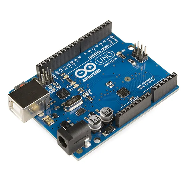
The Microchip datasheet’s first page is a feature list. For the ATmega328P it includes: 32 KB of in-system self-programmable flash, 1 KB EEPROM, 2 KB internal SRAM; 131 instructions, most of them single-clock, giving up to 20 MIPS at 20 MHz; two 8-bit and one 16-bit timer/counter; six PWM channels; a 6-channel 10-bit ADC in the through-hole (SPDIP) package; a USART, an SPI port and an I2C-compatible two-wire interface; a watchdog timer; 23 programmable I/O lines; and an operating voltage of 1.8–5.5 V (full 20 MHz speed needs 4.5–5.5 V). It uses a Harvard architecture — separate paths for program and data.
| Block | What it is | Robot job | Lesson |
|---|---|---|---|
| CPU + clock | Runs instructions at a fixed, known rate | Runs your control loop | 10–11 |
| Flash | Non-volatile program memory | Holds the firmware (your sketch) | 11 |
| SRAM | Fast working memory, lost at power-off | Variables, buffers, the stack | 11 |
| EEPROM | Small non-volatile data memory | Calibration values, servo end points | 11 |
| GPIO | Digital pins in and out | Buttons, limit switches, LEDs, driver enable | 7 |
| ADC | Voltage → number | Knobs, light, battery level | 8 |
| Timers / PWM | Hardware counters and waveforms | Motor speed, servo pulses, steady timing | 9 |
| USART / SPI / I2C | Serial communication blocks | Talk to a PC, sensors, servo drivers | 13 |
| Watchdog | A timer that resets a stuck chip | Recovers firmware that hangs | — |
Arduino’s memory guide puts it simply: flash is where the compiled sketch is stored and executed from; SRAM holds temporary, run-time data such as the variables your functions create; EEPROM keeps data even without power. On the ATmega328P the 2 KB of SRAM is shared between global variables, the heap and the stack — which is why a big array or lots of text can crash an Uno long before the 32 KB of flash is full.
Peripherals work in parallel
The magic of an MCU is that its peripherals are hardware. Once you start PWM on a pin, the timer keeps producing the waveform by itself while the CPU does other work — Arduino’s delay() reference even notes that PWM values and pin states are maintained during a delay. The ADC converts while the CPU waits or does something else; the serial port shifts bits out on its own. Your code’s job is to set up the peripherals, then make decisions.
MCU family tour
Meet the family: six microcontrollers from their datasheets
There are thousands of MCUs. Here are six you will meet in robot labs, with numbers taken from each manufacturer’s datasheet or board page. Read the table like an engineer: not “which is best?” but “which fits this job?”
| Chip (board) | Core, max clock | Flash / SRAM | ADC | Supply / logic |
|---|---|---|---|---|
| ATmega328P (UNO R3) | 8-bit AVR, 20 MHz (16 MHz on the Uno) | 32 KB / 2 KB (+1 KB EEPROM) | 10-bit | 1.8–5.5 V; 5 V on the Uno |
| RA4M1 (UNO R4 WiFi) | Arm Cortex-M4 with FPU, 48 MHz | 256 kB / 32 kB (+8 kB EEPROM) | 14-bit (+12-bit DAC) | 5 V fixed; 8 mA per GPIO |
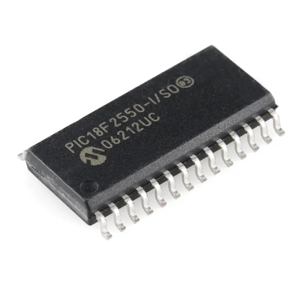
| PIC18F2550 | 8-bit PIC18, up to 48 MHz clock | 32 KB / 2 KB (+256 B EEPROM) | 10-bit, 10 channels | 2.0–5.5 V; on-chip USB |
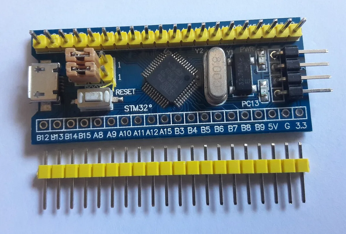
| STM32F103C8 (Blue Pill) | Arm Cortex-M3, 72 MHz | 64 or 128 KB / 20 KB | 2 × 12-bit | 2.0–3.6 V; almost all I/O 5 V-tolerant |
| RP2040 (Raspberry Pi Pico) | Dual Arm Cortex-M0+, up to 133 MHz | 2 MB on the board / 264 kB | 12-bit | 3.3 V I/O |
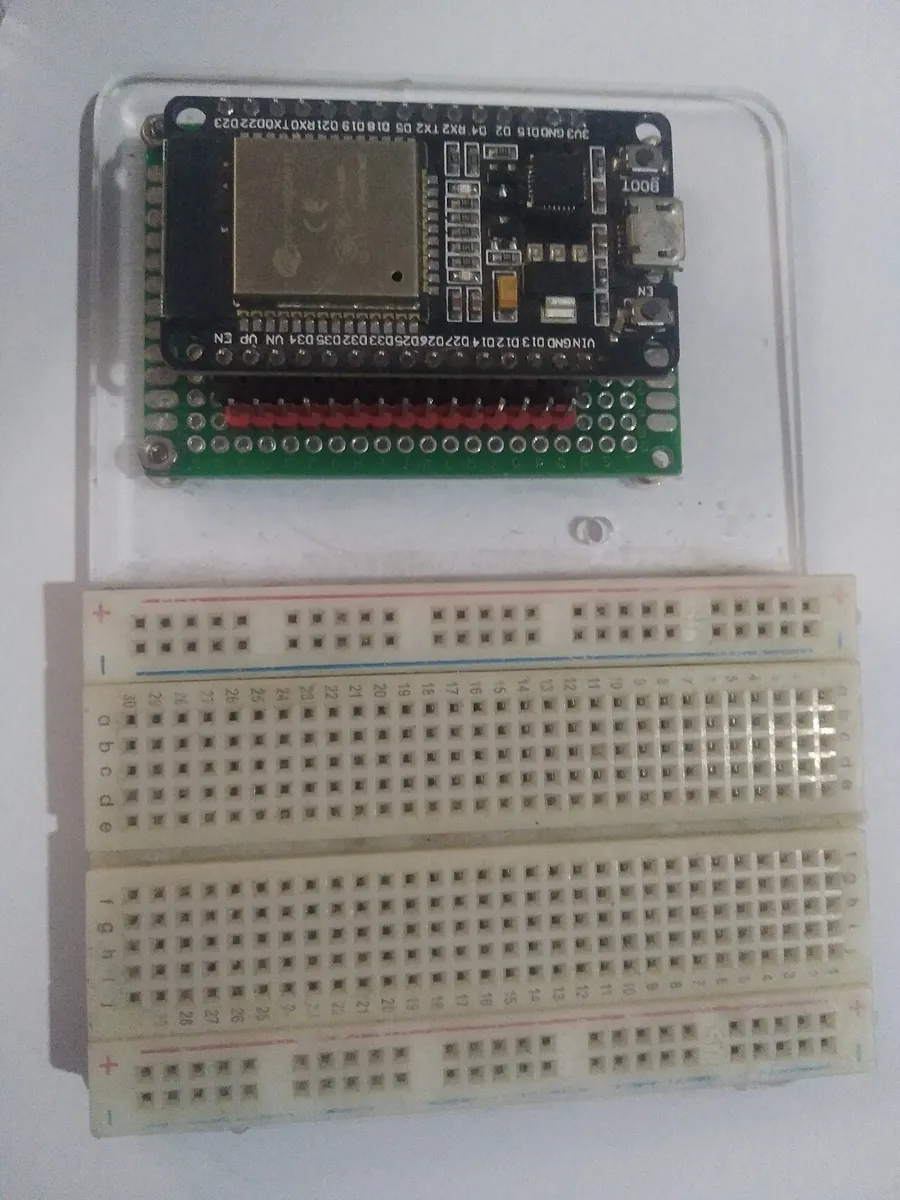
| ESP32 | 1 or 2 Xtensa LX6 cores, 240 MHz | External or in-package / 520 KB | 12-bit, up to 18 channels | 3.3 V class; Wi-Fi + Bluetooth |
MCU vs SBC
MCU or single-board computer? Usually both
A single-board computer (SBC) such as a Raspberry Pi or a Jetson runs a full operating system like Linux. That makes it great for cameras, AI models, ROS, Wi-Fi dashboards and maths-heavy planning. But an operating system juggles many tasks, so the exact moment your code runs can wander — that is jitter. An MCU runs one program with no operating system in the way, and its timers make waveforms in hardware, so its timing is steady.
| Microcontroller (MCU) | Single-board computer (SBC) / PC | |
|---|---|---|
| Starts up | In a moment, straight into your program | Boots an operating system first |
| Timing | Steady; hardware timers for PWM and pulses | Can jitter when the OS is busy |
| Memory | KB to a few hundred KB of SRAM | GB of RAM |
| Good at | Pins, PWM, reading sensors, safety checks, reflexes | Vision, AI, kinematics, planning, user interfaces |
| Pins | Many, with ADC, PWM, timers built in | Fewer; usually no built-in ADC |
| If it crashes | Watchdog can reset it in milliseconds | Restart can take a while |
Visual
Visualise it: three peripherals, one chip
This fake board shows three peripherals that live **inside one microcontroller**: toggle **D7** (GPIO, Lesson 7), drag **A0** (the ADC, Lesson 8) and set the **D9** duty (a timer making PWM, Lesson 9). On a real MCU all three run at the same time, in hardware, while the CPU decides what to do next. Browser simulation only — no real pins or USB devices are touched.
Interactive · GPIO / ADC / PWM Lab
Fake MCU board for digital out, analog in, and PWM duty. Browser-only — never talks to real USB/serial/hardware.
GPIO D7
Good for LEDs / logic — not motors.
ADC A0 (10-bit)
raw 512 → 2.50 V
Pot / distance proxy → robot perception.
PWM D9
duty 40%
PWM → driver → motor — never GPIO-direct.
board@sim ~ pins: D7=0 A0=512 D9=40% · educational MCU only
Code lab
Code lab: compare chips and model loop timing in Python
1. Compare microcontrollers like an engineer
This script holds the datasheet numbers from the table above, prints each chip’s clock period and SRAM compared with the ATmega328P, filters the list for two different robot jobs, and checks whether an example firmware fits in flash and SRAM.
# mcu_compare.py — compare real microcontrollers from their datasheets and pick one for a job.
# Stage 4, Lesson 10. Simulation only: a table and some filters. No pins, no hardware.
# Every number below comes from the manufacturer's datasheet or board page (see the lesson's Sources).

mcus = [
    # name, core, max MHz, flash kB, SRAM kB, ADC bits, supply (datasheet), runs at 5 V?, Wi-Fi
    ("ATmega328P (Uno R3)",     "8-bit AVR",         20,   32,   2, 10, "1.8-5.5 V", True,  False),  # Uno clocks it at 16 MHz
    ("RA4M1 (UNO R4 WiFi)",     "Cortex-M4 + FPU",   48,  256,  32, 14, "5 V fixed", True,  True),   # Wi-Fi via on-board ESP32-S3
    ("PIC18F2550",              "8-bit PIC18",       48,   32,   2, 10, "2.0-5.5 V", True,  False),
    ("STM32F103C8 (Blue Pill)", "Cortex-M3",         72,   64,  20, 12, "2.0-3.6 V", False, False),
    ("RP2040 (Pico)",           "2x Cortex-M0+",    133, 2048, 264, 12, "3.3 V IO",  False, False),  # 2 MB flash is on the Pico board
    ("ESP32",                   "1-2x Xtensa LX6",  240,    0, 520, 12, "2.3-3.6 V", False, True),   # flash is external/in-package
]

print("1) Datasheet snapshot")
print("-" * 86)
print(f"  {'chip':<26}{'core':<17}{'MHz':>5}{'flash kB':>9}{'SRAM kB':>8}{'ADC':>5}  {'supply':<11}{'WiFi':>4}")
for n, core, mhz, fl, ram, adc, sup, _, wifi in mcus:
    fl_s = str(fl) if fl else "ext."
    print(f"  {n:<26}{core:<17}{mhz:>5}{fl_s:>9}{ram:>8}{adc:>5}  {sup:<11}{('yes' if wifi else 'no'):>4}")

print()
print("2) Clock period at maximum speed, and SRAM compared with the ATmega328P")
print("-" * 86)
base_ram = mcus[0][4]
for n, _, mhz, _, ram, *_ in mcus:
    print(f"  {n:<26} one clock = {1000/mhz:6.2f} ns   SRAM x{ram/base_ram:6.1f}")
print("  (The Uno R3 runs its ATmega328P at 16 MHz = 62.5 ns per clock, below the 20 MHz maximum.)")
print("  Clock speed is not the whole story: cores do different amounts of work per clock.")

print()
print("3) Pick a chip: robot needs >= 12-bit ADC, 5 V logic (old shields), no Wi-Fi needed")
print("-" * 86)
for n, _, _, _, _, adc, _, five_v, _ in mcus:
    ok = adc >= 12 and five_v
    print(f"  {n:<26} {'MATCH' if ok else '-'}")

print()
print("4) Pick a chip: wireless teach pendant, 3.3 V sensors, big SRAM for buffers")
print("-" * 86)
for n, _, _, _, ram, _, _, five_v, wifi in mcus:
    ok = wifi and ram >= 256 and not five_v
    print(f"  {n:<26} {'MATCH' if ok else '-'}")

print()
print("5) Does my firmware fit? (example sizes from a compile report)")
print("-" * 86)
need_flash_kB, need_ram_kB = 18.4, 1.7
for n, _, _, fl, ram, *_ in mcus[:2]:
    print(f"  {n:<26} flash {need_flash_kB/fl*100:5.1f}% used, SRAM {need_ram_kB/ram*100:5.1f}% used"
          + ("   <- SRAM tight!" if need_ram_kB / ram > 0.75 else ""))
Output (run with python3 mcu_compare.py)
1) Datasheet snapshot
--------------------------------------------------------------------------------------
  chip                      core               MHz flash kB SRAM kB  ADC  supply     WiFi
  ATmega328P (Uno R3)       8-bit AVR           20       32       2   10  1.8-5.5 V    no
  RA4M1 (UNO R4 WiFi)       Cortex-M4 + FPU     48      256      32   14  5 V fixed   yes
  PIC18F2550                8-bit PIC18         48       32       2   10  2.0-5.5 V    no
  STM32F103C8 (Blue Pill)   Cortex-M3           72       64      20   12  2.0-3.6 V    no
  RP2040 (Pico)             2x Cortex-M0+      133     2048     264   12  3.3 V IO     no
  ESP32                     1-2x Xtensa LX6    240     ext.     520   12  2.3-3.6 V   yes

2) Clock period at maximum speed, and SRAM compared with the ATmega328P
--------------------------------------------------------------------------------------
  ATmega328P (Uno R3)        one clock =  50.00 ns   SRAM x   1.0
  RA4M1 (UNO R4 WiFi)        one clock =  20.83 ns   SRAM x  16.0
  PIC18F2550                 one clock =  20.83 ns   SRAM x   1.0
  STM32F103C8 (Blue Pill)    one clock =  13.89 ns   SRAM x  10.0
  RP2040 (Pico)              one clock =   7.52 ns   SRAM x 132.0
  ESP32                      one clock =   4.17 ns   SRAM x 260.0
  (The Uno R3 runs its ATmega328P at 16 MHz = 62.5 ns per clock, below the 20 MHz maximum.)
  Clock speed is not the whole story: cores do different amounts of work per clock.

3) Pick a chip: robot needs >= 12-bit ADC, 5 V logic (old shields), no Wi-Fi needed
--------------------------------------------------------------------------------------
  ATmega328P (Uno R3)        -
  RA4M1 (UNO R4 WiFi)        MATCH
  PIC18F2550                 -
  STM32F103C8 (Blue Pill)    -
  RP2040 (Pico)              -
  ESP32                      -

4) Pick a chip: wireless teach pendant, 3.3 V sensors, big SRAM for buffers
--------------------------------------------------------------------------------------
  ATmega328P (Uno R3)        -
  RA4M1 (UNO R4 WiFi)        -
  PIC18F2550                 -
  STM32F103C8 (Blue Pill)    -
  RP2040 (Pico)              -
  ESP32                      MATCH

5) Does my firmware fit? (example sizes from a compile report)
--------------------------------------------------------------------------------------
  ATmega328P (Uno R3)        flash  57.5% used, SRAM  85.0% used   <- SRAM tight!
  RA4M1 (UNO R4 WiFi)        flash   7.2% used, SRAM   5.3% used
2. Why steady timing belongs on an MCU
This script uses a seeded random model (so the output repeats exactly) to compare 500 servo updates from a hardware timer, from an MCU loop and from a busy desktop script. It then counts how much work fits in one loop on a 16 MHz Uno, using Arduino’s figure of about 100 µs per analogRead(). The jitter numbers are illustrations, not measurements — the bench sketch below lets you measure a real board.
# loop_timing.py — why steady timing belongs on a microcontroller.
# Stage 4, Lesson 10. Simulation only: a seeded random model, no real OS or hardware is measured.
import random

random.seed(10)
PERIOD_MS = 20.0     # a hobby servo expects a fresh pulse about every 20 ms (50 Hz)
N = 500              # 10 seconds of updates


def run(name, jitter):
    """jitter() returns extra delay in ms added to each update."""
    late, worst, t_prev, gaps = 0, 0.0, 0.0, []
    for i in range(1, N + 1):
        t = i * PERIOD_MS + jitter()
        gap = t - t_prev
        gaps.append(gap)
        t_prev = t
        worst = max(worst, gap)
        if gap > PERIOD_MS * 1.25:
            late += 1
    mean = sum(gaps) / len(gaps)
    print(f"  {name:<34} mean gap {mean:6.2f} ms, worst {worst:6.2f} ms, late updates {late:3d}/{N}")


print("1) 500 servo updates, ideal period 20 ms (illustrative jitter models)")
print("-" * 80)
run("MCU hardware timer", lambda: random.uniform(-0.002, 0.002))
run("MCU loop() with small work", lambda: random.uniform(0.0, 0.3))
run("Desktop script, busy machine", lambda: random.expovariate(1 / 2.0) + (35 if random.random() < 0.02 else 0))

print()
print("2) How much work fits in one loop on a 16 MHz Uno?")
print("-" * 80)
F = 16_000_000
for loop_ms in (1, 5, 20):
    cycles = F * loop_ms / 1000
    adc_reads = int(loop_ms * 1000 / 100)   # Arduino: about 100 us per analogRead() on an Uno
    print(f"  {loop_ms:2d} ms loop = {cycles:9,.0f} clock cycles, or about {adc_reads:3d} analogRead() calls and nothing else")

print()
print("3) The split most robot arms use")
print("-" * 80)
for job, where in (("Servo pulses, PWM, encoder counting", "MCU timers / interrupts"),
                   ("Read sensors, soft limits, e-stop", "MCU loop, every few ms"),
                   ("Inverse kinematics, path planning", "PC / SBC (Linux, ROS)"),
                   ("Camera, AI, user interface", "PC / SBC")):
    print(f"  {job:<38} -> {where}")
Output (run with python3 loop_timing.py)
1) 500 servo updates, ideal period 20 ms (illustrative jitter models)
--------------------------------------------------------------------------------
  MCU hardware timer                 mean gap  20.00 ms, worst  20.00 ms, late updates   0/500
  MCU loop() with small work         mean gap  20.00 ms, worst  20.29 ms, late updates   0/500
  Desktop script, busy machine       mean gap  20.00 ms, worst  56.95 ms, late updates  33/500

2) How much work fits in one loop on a 16 MHz Uno?
--------------------------------------------------------------------------------
   1 ms loop =    16,000 clock cycles, or about  10 analogRead() calls and nothing else
   5 ms loop =    80,000 clock cycles, or about  50 analogRead() calls and nothing else
  20 ms loop =   320,000 clock cycles, or about 200 analogRead() calls and nothing else

3) The split most robot arms use
--------------------------------------------------------------------------------
  Servo pulses, PWM, encoder counting    -> MCU timers / interrupts
  Read sensors, soft limits, e-stop      -> MCU loop, every few ms
  Inverse kinematics, path planning      -> PC / SBC (Linux, ROS)
  Camera, AI, user interface             -> PC / SBC
Real world
Where microcontrollers sit in real robots
- Robot arms: an MCU or servo driver produces the joint pulses and checks limit switches, while a PC plans the motion.
- 3D printers and CNC machines: an MCU reads the G-code line by line and steps the motors with precise timing.
- Drones: a flight controller MCU reads motion sensors and updates the motors many times a second.
- Wireless gadgets: ESP32-class chips combine an MCU with Wi-Fi and Bluetooth — remote controls, sensor nodes, teach pendants.
- Motor drives: chips like the STM32F103 include motor-control PWM timers with dead time and an emergency-stop input (ST product page).
- USB devices: chips with built-in USB, like the PIC18F2550 or the ATmega16U2 on the UNO R3, become keyboards, adapters and programmers.
Bench build
Bench build: measure your own microcontroller
You need only a board and its USB cable — nothing is connected to any pin. The sketch counts how many times loop() runs per second, records the slowest pass, and blinks the on-board LED as a heartbeat without using delay().
Read the board
Find the main chip and read its markings. Look up its datasheet and write down flash, SRAM, clock and supply voltage.
Upload
Upload
loop_timer.ino(Lesson 11 covers uploading step by step). Open the Serial Monitor at 9600 baud.Watch
Write down loops per second and the worst pass in microseconds for ten seconds.
Add work
Add a second
analogRead()and then adelay(5)insideloop(). Upload again. What happens to loops/s and the worst pass?Compare
If you have two boards (an UNO R3 and an UNO R4, say), run the same sketch on both and compare.
// loop_timer.ino — measure how fast (and how steadily) your microcontroller runs loop()
// (Stage 4, Lesson 10). For a REAL board on your bench. This sketch is not run inside the browser.
//
// Needs nothing but the board and its USB cable. The on-board LED (pin 13 on an Uno) blinks as a
// heartbeat. Nothing is connected to any pin, so nothing can be damaged.
// If you later add parts: a pin only SIGNALS. Motors, servos and relays need a driver and their own
// supply with a common ground (Lessons 6 and 9). Never put 5 V on a 3.3 V board's pins.

const int LED_PIN = LED_BUILTIN;
const int SENSOR_PIN = A0;               // left unconnected here: we only time the read

unsigned long lastReport = 0;
unsigned long lastBlink = 0;
unsigned long loops = 0;
unsigned long slowLoops = 0;             // passes that took longer than 1000 us
unsigned long worstUs = 0;
unsigned long prevUs = 0;
bool ledOn = false;

void setup() {
  pinMode(LED_PIN, OUTPUT);
  Serial.begin(9600);
  prevUs = micros();
}

void loop() {
  unsigned long nowUs = micros();        // resolution is 4 us on 16 MHz boards
  unsigned long passUs = nowUs - prevUs; // unsigned subtraction: safe across rollover
  prevUs = nowUs;
  if (passUs > worstUs) worstUs = passUs;
  if (passUs > 1000) slowLoops++;
  loops++;

  analogRead(SENSOR_PIN);                // some real work: about 100 us on an Uno

  if (millis() - lastBlink >= 500) {     // heartbeat without delay()
    lastBlink = millis();
    ledOn = !ledOn;
    digitalWrite(LED_PIN, ledOn ? HIGH : LOW);
  }

  if (millis() - lastReport >= 1000) {   // once a second, print and reset the counters
    lastReport = millis();
    Serial.print("loops/s "); Serial.print(loops);
    Serial.print("  worst pass "); Serial.print(worstUs); Serial.print(" us");
    Serial.print("  passes > 1 ms "); Serial.println(slowLoops);
    loops = 0; slowLoops = 0; worstUs = 0;
  }
}Debugging
Debugging: when the microcontroller misbehaves
| Symptom | Likely cause | Fix |
|---|---|---|
| Board resets when a motor or servo moves | Brownout: the load is on the board’s supply | Separate load supply, common ground (Lesson 9) |
| Sketch behaves strangely after adding a big array or many messages | SRAM is full (stack and globals collide) | Check the IDE’s memory report; shrink buffers; use F() for text (Lesson 11) |
| A 3.3 V board stopped responding after connecting a 5 V sensor | Over-voltage on a non-tolerant pin | Level shifter or divider (Lesson 7); check the datasheet first |
| Timing drifts or a loop runs slowly | Blocking delay() or slow code inside loop() | Measure with micros(); make the loop non-blocking |
| Readings or PWM change when switching boards | Different ADC bits, PWM pins or frequencies | Read each board’s reference pages; don’t assume UNO R3 behaviour |
| Board gets warm with nothing connected | Possible short or damaged chip | Unplug at once; inspect for solder bridges or stray wires |
Think
Think about it
Think
Meera wants to move her arm project from an UNO R3 to an ESP32 board “because it is 15 times faster”. Her arm uses 5 V servos on a separate supply, a 5 V ultrasonic sensor and a potentiometer on the board’s 5 V. What must she check before she swaps boards?
Experiment
Try it in the lab: compare chips and time a loop
Twenty minutes with the GPIO / ADC / PWM lab, the two Python scripts and your notebook. You will read MCUs the way engineers do — by their datasheets — and see why steady timing matters.
Experiment
Compare chips and time a loop
You will need
- GPIO / ADC / PWM lab (below, runs in your browser)
- Notebook or a text file
- Optional: your laptop to run `mcu_compare.py` and `loop_timing.py`
Steps
- In the lab, toggle D7, move A0 and change D9. For each, write the MCU block that does the work (GPIO, ADC, timer/PWM).
- Run `mcu_compare.py`. Copy the one-clock time for the ATmega328P at its 16 MHz Uno speed and for the ESP32. Write one sentence on why clock speed alone doesn’t decide.
- Write which chip from the table you would choose for (a) a 5 V shield-based arm, (b) a wireless teach pendant, (c) a motor controller with an emergency-stop input. Give one datasheet reason for each.
- Run `loop_timing.py`. Copy the late-update counts for the MCU timer and the busy desktop.
- Draw a box diagram of your robot with two boxes, “MCU” and “PC/SBC”, and put each job from part 3 of the script in the right box.
Interactive · GPIO / ADC / PWM Lab
Fake MCU board for digital out, analog in, and PWM duty. Browser-only — never talks to real USB/serial/hardware.
GPIO D7
Good for LEDs / logic — not motors.
ADC A0 (10-bit)
raw 512 → 2.50 V
Pot / distance proxy → robot perception.
PWM D9
duty 40%
PWM → driver → motor — never GPIO-direct.
board@sim ~ pins: D7=0 A0=512 D9=40% · educational MCU only
An MCU is a small computer whose peripherals do the timing-critical work in hardware. Choose one by the job — pins, ADC, timers, memory, voltage and connectivity — and let a bigger computer do the heavy thinking.
Knowledge check
Check your understanding
Knowledge check
1. A microcontroller typically puts which of these on one chip?
2. On an Arduino, where is your compiled sketch stored?
3. How much SRAM does the ATmega328P on an UNO R3 have?
4. Why is a servo pulse train usually produced by an MCU’s timer rather than a desktop script?
5. The UNO R4 WiFi’s main microcontroller is…
6. How much current can each UNO R4 GPIO safely handle, according to its datasheet?
7. An ESP32’s supply pins are rated about 2.3–3.6 V. What does that mean for a 5 V sensor output?
8. Which job belongs on the PC/SBC rather than the MCU in a typical robot arm?
9. What does a watchdog timer do?
10. Which feature from ST’s STM32F103C8 page is especially useful for motor control?
Mini assignment
Hands-on assignment
Mini assignment
Choose the microcontroller for your robot
Pick an MCU (or a board) for your robot using datasheets, not guesses — and write down which jobs it does and which jobs a bigger computer does.
Deliverables
- A requirements list: number of servos/motors, sensors (digital, analog, serial), logic voltage of each part, wireless or not, memory you expect to need.
- A comparison of at least three MCUs or boards with numbers from their datasheets (and the page or section for each number).
- Your choice and three reasons, plus one risk (for example 3.3 V logic or 8 mA per pin) and how you will handle it.
- A role card: MCU jobs vs PC/SBC jobs, as boxes and arrows.
- Output of `mcu_compare.py` with your own chips added, and `loop_timing.py` with your own loop period.
- If you have a board: the Serial Monitor output from `loop_timer.ino`, before and after adding `delay(5)`.
Do this, step by step
- List your robot’s needs: servos/motors, sensors (digital, analog, serial), logic voltages, wireless, memory.
- Compare three boards (e.g. Uno R3, ESP32, Pico) using numbers from their datasheets, with page/section noted.
- Pick one, give three reasons and one risk with how you’ll handle it.
- Draw a role card: MCU jobs vs PC/SBC jobs.
- Add your chips to
mcu_compare.py, runloop_timing.pywith your loop period, and (if you have a board) runloop_timer.inobefore and afterdelay(5).
Stuck? Hints, one at a time
- Hint 1: Count pins honestly: 6 servos + 4 sensors + 2 LEDs + 1 e-stop already needs about 13 I/O.
- Hint 2: The classic Uno R3 runs at 16 MHz with 32 kB flash and 2 kB SRAM; ESP32 and Pico are 3.3 V boards — note that as a risk if your sensors are 5 V.
- Hint 3: Real-time pin work (PWM, encoders, e-stop) belongs on the MCU; vision and planning belong on the PC/SBC.
- Hint 4: After
delay(5),loop_timer.inoshould show the loop period jump by about 5 ms — that is time the MCU was not listening.
Challenges (pick by level)
- 🟢 Easy: How long is one clock cycle at 16 MHz? *Hint:* 1 ÷ 16 000 000 s. *Check:* the note under part 2 of
mcu_compare.py. - 🟢 Easy: Name the three kinds of memory on the ATmega328P and one thing each would store in a robot arm.
- 🟡 Medium: A sketch needs 1.9 KB of SRAM. Which chips in the table can run it comfortably (under 75%)? *Hint:* edit part 5.
- 🟡 Medium: List three differences you must check before moving a sketch from an UNO R3 to an UNO R4 WiFi. *Hint:* per-pin current, ADC bits, the main chip.
- 🟠 Hard-ish: Measure
loop_timer.inoon a real board, then addSerial.println()of a long message every pass. Explain the change in loops/s. - 🔴 Hard: Read the ATmega328P datasheet’s watchdog chapter and describe how a watchdog could stop an arm if the firmware hangs. *Hint:* what should the outputs do on reset?
- ⚫ Expert: Compare the ESP32’s LED PWM and motor PWM peripherals in its datasheet with the ATmega328P’s timers. Which would you use for six servos, and why? *Hint:* channel count and resolution.
Next step
You know what the chip is. In Lesson 11 — Arduino & Embedded Programming you will program it properly: the shape of a sketch, setup() and loop(), uploading with the IDE, the Serial Monitor, non-blocking timing with millis(), and saving precious SRAM.
Tip: explain today’s chapter with the chai stall — the recipe card is flash, the counter tray is SRAM, the notebook is EEPROM, the hatches are peripherals, and the stall never closes for an update.
Look back: Lesson 9: PWM & Motor/Servo Control. Next: Lesson 11: Arduino & Embedded Programming. Related: Stage 0 — The Robot Brain, Stage 3 — Linux and later Stage 10 — ROS 2.
Sources
- Microchip ATmega48A/PA/88A/PA/168A/PA/328/P datasheet — feature list: 32 KB flash, 1 KB EEPROM, 2 KB SRAM, 131 instructions, 20 MIPS at 20 MHz, timers, six PWM, 10-bit ADC, USART/SPI/I2C, watchdog, 23 I/O lines, 1.8–5.5 V, Harvard architecture, 40 mA per pin.
- Arduino UNO R3 and its datasheet (PDF) — ATmega328P and ATmega16U2, 16 MHz, 32 kB / 2 kB / 1 kB, VIN maximum 6–20 V.
- Arduino UNO R4 WiFi and its datasheet (PDF) — RA4M1 48 MHz Cortex-M4, 256 kB / 32 kB / 8 kB, 14-bit ADC, 12-bit DAC, 5 V, ESP32-S3 at 3.3 V via a level translator, 8 mA per GPIO, VIN 6–24 V.
- Arduino Memory Guide — flash, SRAM, EEPROM; SRAM sections; board memory table.
- Arduino reference: delay() and micros() — PWM and pin states kept during delay(); 4 µs micros() resolution on 16 MHz boards.
- Arduino reference: analogRead() — about 100 µs per read on ATmega boards.
- Microchip PIC18F2455/2550/4455/4550 datasheet (DS39632E) — USB 2.0, 32 KB flash, 2048 B SRAM, 256 B EEPROM, 10-bit ADC, up to 48 MHz, 2.0–5.5 V.
- Wikipedia — STM32 (F1 series table) and the STMicroelectronics STM32F103C8 product page (st.com blocks automated checks) — 72 MHz Cortex-M3, 64/128 KB flash, 20 KB SRAM, 2 × 12-bit ADC, motor-control PWM timer with dead time and emergency stop, 2.0–3.6 V, almost all I/O 5 V-tolerant.
- Espressif ESP32 Series datasheet (PDF) — Xtensa LX6 single/dual core up to 240 MHz, 520 KB SRAM, Wi-Fi + Bluetooth, 34 GPIOs, 12-bit SAR ADC up to 18 channels, LED PWM up to 16 channels, 2.3–3.6 V supply pins.
- Raspberry Pi Pico datasheet (PDF) — RP2040 dual Cortex-M0+ up to 133 MHz, 264 kB SRAM, 2 MB flash on the board, 3.3 V I/O.
- SparkFun Learn: What is an Arduino? — board plus IDE, no separate programmer needed, the Uno’s 14 digital pins (6 PWM) and 6 analog inputs.
- Photos: Wikimedia Commons (credits under each image).
Self-attested for now — keep artifacts in your lab notebook.
Complete
Today's goal
0 of 1 done today
Mark this lesson complete when you have worked the experiment, knowledge check, and assignment (even roughly).