
Electronics & Embedded Systems · Lesson 15
Capstone: Build a Virtual Robot Circuit
Est. 90–120 min
Why
Why a capstone: everything at once
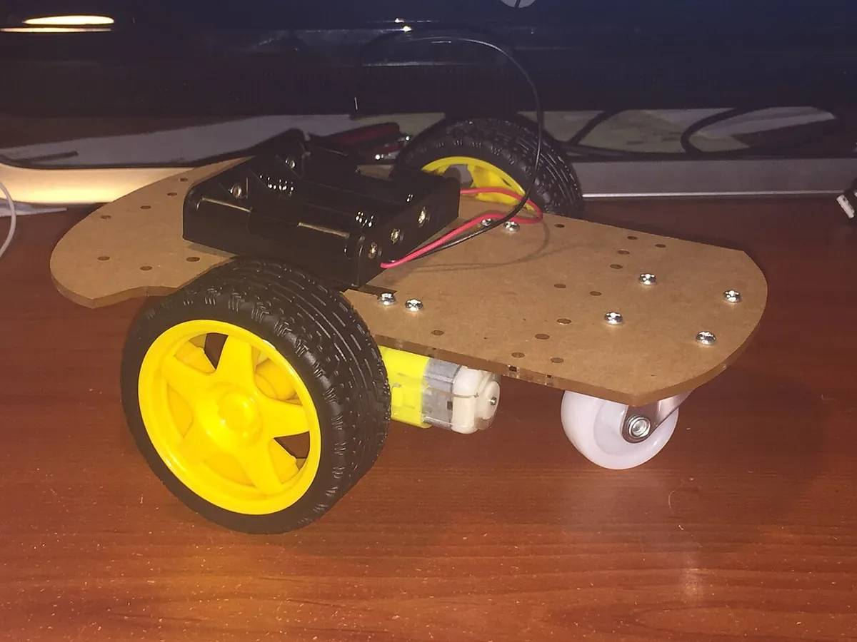
This capstone uses every lesson of Stage 4. You will design a small rover's complete electronics — a range sensor, a drive motor through a driver, a steering servo on an I²C servo driver, telemetry over serial, separate power rails and a hardware stop — then review it with a checker and run it in a simulation. Only then is it worth building.
By the end you will be able to: turn a brief into a pin map and parts list; check pins against the UNO R3's serial, I²C, SPI and PWM pins; budget every rail with margin; design sense → decide → act logic that treats “no reading” as unsafe; convert a servo angle into PCA9685 ticks; and present your design with a review score, a simulation log and a safety case.
Concept
The brief: a small rover that won't hit the wall
| Requirement | How | Lessons |
|---|---|---|
| Measure distance ahead | HC-SR04 on pins 7/8, 60 ms cycle, timeout, 0 = unknown | 12 |
| Drive forward at variable speed | Motor driver: PWM on pin 5 (~), direction on pin 4 | 6, 9 |
| Steer | Servo on a PCA9685 I²C driver (A4/A5, address 0x40) | 9, 13 |
| Report status | Telemetry at 115200 8N1 over USB; pins 0/1 left free | 11, 13 |
| Stay responsive | Non-blocking loop; safety check every pass | 11 |
| Power safely | Logic rail + actuator rail, 25% margin, common ground | 2, 5, 14 |
| Stop safely | Hardware e-stop cuts actuator rail; pin 2 lets code know | 14 |
Rules the design must pass
- Arduino's UNO R3 page: PWM only on pins 3, 5, 6, 9, 10, 11; I²C on A4 (SDA) / A5 (SCL); SPI on 10–13; pins 0/1 are the USB serial port.
- No pin used twice; no two I²C devices at the same address (PCA9685 default 0x40, LSM6DS3 0x6B).
- No servo or motor on the logic rail; every rail's load × 1.25 within its supply.
- 3.3 V parts level-shifted from 5 V logic (Lesson 12).
- Common ground between MCU, drivers, sensors and actuator supply.
- The e-stop cuts actuator power in hardware.
From angle to PCA9685 ticks
Adafruit's PCA9685 library sets each channel with an on and off tick between 0 and 4095 — a 12-bit counter across one PWM period. At 50 Hz the period is 20 ms, so one tick is about 4.9 µs. If your servo moves 0–180° for 1.0–2.0 ms pulses (check its datasheet — ranges vary), 90° is 1.5 ms ≈ 307 ticks.
ticks = pulse (µs) ÷ 20 000 µs × 4096
- 1000 µs → 205 ticks, 1500 µs → 307 ticks, 2000 µs → 410 ticks
- 120° → 1667 µs → 341 ticks; 150° → 1833 µs → 375 ticks
Design review
Step 1: review the design on paper
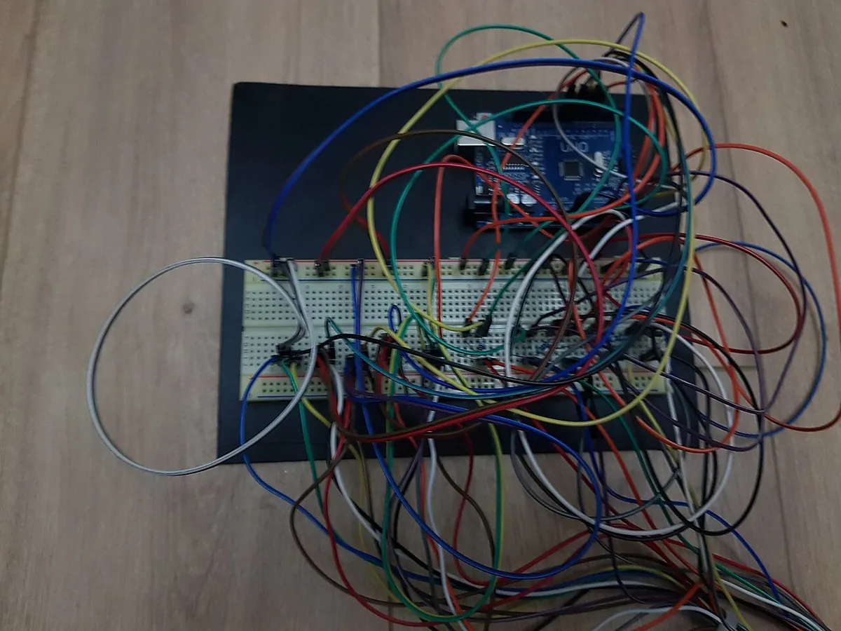
The checker reads the pin map, parts and rails and tests every rule above. Fix all FAIL lines before you simulate — try breaking it on purpose to see each check fire.
"""capstone_review.py - design review for the Stage 4 capstone circuit (Lesson 15).

Pure Python checker. It reads a pin map and parts list for an Arduino UNO R3-style board and
checks it against what Stage 4 taught: pins 0/1 are the USB serial port, A4/A5 are I2C,
10-13 are SPI, PWM only on pins 3, 5, 6, 9, 10, 11 (UNO R3 docs), 40 mA absolute max per pin,
actuators on their own supply with a common ground, I2C addresses unique, a real e-stop.
"""
import re

PWM_PINS = {3, 5, 6, 9, 10, 11}
SERIAL_PINS = {0, 1}
I2C_PINS = {"A4", "A5"}
SPI_PINS = {10, 11, 12, 13}

pin_map = {
    "TRIG (HC-SR04)": 7,
    "ECHO (HC-SR04)": 8,
    "Motor driver PWM": 5,
    "Motor driver DIR": 4,
    "Stop-button sense": 2,
    "Status LED": 13,
    "PCA9685 SDA": "A4",
    "PCA9685 SCL": "A5",
}
parts = [
    {"name": "PCA9685 servo driver", "i2c": 0x40, "rail": "logic 5V"},
    {"name": "LSM6DS3 IMU", "i2c": 0x6B, "rail": "3.3V", "level_shifted": True},
    {"name": "3 x servo (on PCA9685 V+)", "ma": 2100, "rail": "actuator 6V"},
    {"name": "Gear motor via driver", "ma": 600, "rail": "actuator 6V"},
    {"name": "HC-SR04", "ma": 15, "rail": "logic 5V"},
]
rails = {"logic 5V": 500, "3.3V": 50, "actuator 6V": 4000}   # supply capability in mA
common_ground = True
estop_cuts_actuator_rail = True

checks = []


def check(ok, text):
    checks.append((ok, text))


used = {}
for signal, pin in pin_map.items():
    check(pin not in used, f"pin {pin} used once ({signal})" if pin not in used else f"pin {pin} clash: {used[pin]} / {signal}")
    used[pin] = signal
check(not any(p in SERIAL_PINS for p in pin_map.values()), "pins 0/1 left free for USB serial upload + telemetry")
check(pin_map["Motor driver PWM"] in PWM_PINS, f"motor PWM on a PWM pin (~{pin_map['Motor driver PWM']})")
check({pin_map["PCA9685 SDA"], pin_map["PCA9685 SCL"]} == I2C_PINS, "I2C on A4 (SDA) / A5 (SCL)")
spi_hits = [s for s, p in pin_map.items() if p in SPI_PINS]
check(True, f"SPI pins 10-13 in use by: {', '.join(spi_hits) or 'none'} (fine while no SPI device is fitted)")
addrs = [p["i2c"] for p in parts if "i2c" in p]
check(len(addrs) == len(set(addrs)), "I2C addresses unique: " + ", ".join(f"0x{a:02X}" for a in addrs))
check(all(p.get("level_shifted") for p in parts if p["rail"] == "3.3V"), "3.3 V parts level-shifted from 5 V logic")
for rail, cap in rails.items():
    load = sum(p.get("ma", 0) for p in parts if p["rail"] == rail)
    check(load * 1.25 <= cap, f"{rail}: {load} mA x 1.25 = {load * 1.25:.0f} mA <= {cap} mA")
check(not any(re.search(r"x servo|motor", p["name"]) and p["rail"] != "actuator 6V" for p in parts), "no servo or motor on the logic rail")
check(common_ground, "common ground: MCU, drivers, sensors, actuator supply")
check(estop_cuts_actuator_rail, "e-stop cuts actuator power (software stop is extra, not the e-stop)")

passed = sum(ok for ok, _ in checks)
for ok, text in checks:
    print(f"   [{'PASS' if ok else 'FAIL'}] {text}")
print(f"\nScore: {passed}/{len(checks)} checks passed")
print("Verdict:", "ready for the virtual build" if passed == len(checks) else "fix the FAIL lines first")
Output (run with python3 capstone_review.py)
   [PASS] pin 7 used once (TRIG (HC-SR04))
   [PASS] pin 8 used once (ECHO (HC-SR04))
   [PASS] pin 5 used once (Motor driver PWM)
   [PASS] pin 4 used once (Motor driver DIR)
   [PASS] pin 2 used once (Stop-button sense)
   [PASS] pin 13 used once (Status LED)
   [PASS] pin A4 used once (PCA9685 SDA)
   [PASS] pin A5 used once (PCA9685 SCL)
   [PASS] pins 0/1 left free for USB serial upload + telemetry
   [PASS] motor PWM on a PWM pin (~5)
   [PASS] I2C on A4 (SDA) / A5 (SCL)
   [PASS] SPI pins 10-13 in use by: Status LED (fine while no SPI device is fitted)
   [PASS] I2C addresses unique: 0x40, 0x6B
   [PASS] 3.3 V parts level-shifted from 5 V logic
   [PASS] logic 5V: 15 mA x 1.25 = 19 mA <= 500 mA
   [PASS] 3.3V: 0 mA x 1.25 = 0 mA <= 50 mA
   [PASS] actuator 6V: 2700 mA x 1.25 = 3375 mA <= 4000 mA
   [PASS] no servo or motor on the logic rail
   [PASS] common ground: MCU, drivers, sensors, actuator supply
   [PASS] e-stop cuts actuator power (software stop is extra, not the e-stop)

Score: 20/20 checks passed
Verdict: ready for the virtual build
Visual
Visualise it: validate the full architecture
Final architecture validation: build your capstone in the lab until it reads Embedded Robot Ready — and leave it green. Then tick the unsafe GPIO-to-motor block once to remind yourself why the driver is there. Browser simulation only.
Interactive · Robot Electronics Wiring Lab
Assemble a full educational architecture: power, common ground, MCU, driver, actuators, sensors, and clean signal paths. Unlock Embedded Robot Ready.
- Missing: Dedicated low-voltage PSU for actuators
- Missing: Common ground MCU ↔ driver ↔ sensors
- Missing: MCU / embedded brain present
- Missing: Motor/servo driver between MCU and actuator
- …+3 more
Low-voltage educational sim · sims ≠ datasheets · never access real hardware from the browser.
Simulation
Step 2: run the virtual robot
The simulation drives the rover towards a wall, every 60 ms: cruise above 40 cm, slow and steer between 20 and 40 cm, stop and turn below 20 cm, stop on no echo, and latch everything off when the e-stop is pressed. The servo column shows the PCA9685 ticks for each angle.
"""capstone_sim.py - a virtual robot running sense -> decide -> act (Stage 4, Lesson 15).

Pure Python simulation of the capstone circuit: HC-SR04-style range sensor, one steering
servo on a PCA9685-style driver (4096 ticks per period at 50 Hz), one drive motor through a
driver (PWM 0-255), a stop latch and serial telemetry. No hardware is touched.
"""

import random

random.seed(4)                       # same "random" world every run, so the output is repeatable

PERIOD_US = 20000                    # 50 Hz servo frame
TICKS = 4096                         # PCA9685: 12-bit counter per period
STOP_CM, SLOW_CM = 20, 40


def servo_ticks(angle):
    pulse_us = 1000 + angle / 180 * 1000          # 1.0 ms .. 2.0 ms (check your servo's range)
    return round(pulse_us / PERIOD_US * TICKS)


def sense(t):
    """Distance the robot 'sees' at step t: a wall getting closer, then a timeout glitch."""
    if t == 7:
        return 0                                  # pulseIn() timed out -> 0
    return max(5, 90 - t * 9 + random.randint(-2, 2))


def decide(dist_cm, estop):
    if estop:
        return "STOPPED (e-stop)", 0, 90
    if dist_cm == 0:
        return "NO ECHO -> stop", 0, 90           # treat 'no reading' as unsafe, never as 'far away'
    if dist_cm < STOP_CM:
        return "TOO CLOSE -> stop + turn", 0, 150
    if dist_cm < SLOW_CM:
        return "SLOW", 90, 120
    return "CRUISE", 180, 90


print(f"{'t(ms)':>6} {'dist':>6}  {'decision':<24} {'motor':>5} {'servo':>5} {'ticks':>5}")
estop = False
for step in range(12):
    t_ms = step * 60                              # 60 ms loop = the HC-SR04 cycle
    if step == 10:
        estop = True                              # someone hits the red button
    d = sense(step)
    state, motor_pwm, angle = decide(d, estop)
    print(f"{t_ms:>6} {d:>4}cm  {state:<24} {motor_pwm:>5} {angle:>4}d {servo_ticks(angle):>5}")

print("\nTelemetry line format (115200 8N1): t,dist,state,motor,servo")
print("   example -> 360,34,SLOW,90,120")
print("E-stop latched: actuator power relay OFF, restart needs a human reset.")
Output (run with python3 capstone_sim.py)
 t(ms)   dist  decision                 motor servo ticks
     0   89cm  CRUISE                     180   90d   307
    60   81cm  CRUISE                     180   90d   307
   120   70cm  CRUISE                     180   90d   307
   180   64cm  CRUISE                     180   90d   307
   240   55cm  CRUISE                     180   90d   307
   300   44cm  CRUISE                     180   90d   307
   360   34cm  SLOW                        90  120d   341
   420    0cm  NO ECHO -> stop              0   90d   307
   480   16cm  TOO CLOSE -> stop + turn     0  150d   375
   540    7cm  TOO CLOSE -> stop + turn     0  150d   375
   600    5cm  STOPPED (e-stop)             0   90d   307
   660    5cm  STOPPED (e-stop)             0   90d   307

Telemetry line format (115200 8N1): t,dist,state,motor,servo
   example -> 360,34,SLOW,90,120
E-stop latched: actuator power relay OFF, restart needs a human reset.Real world
Where this exact pattern runs
- Robot vacuums and warehouse robots run the same sense → decide → act loop with stop zones and safe defaults.
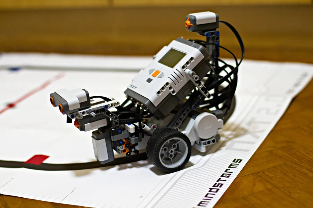
- Line followers and school competitions use this exact stack: sensor, MCU, driver, motors, battery.
- Industrial robot cells treat lost sensor data as a stop condition and wire e-stops that remove motor power.
- Your 6DOF arm later in the course: same layers, more joints — a servo driver over I²C, a separate servo rail and a hardware stop.
Bench build
Step 3 (optional): the real sketch
Build the logic side first
UNO, HC-SR04, PCA9685 and stop sense — USB power only. Check telemetry in the Serial Monitor at 115200.
Add the actuator rail
Separate supply with a fuse, bulk capacitor and the hardware e-stop switch in series. Join grounds.
Wheels in the air
Bring an object towards the sensor: cruise, slow, stop and turn. Press the e-stop: motors and servo lose power at once.
On the floor
Only after all three behaviours and the e-stop work in the air.
// capstone_rover.ino — sense -> decide -> act, non-blocking, safety first (Stage 4, Lesson 15).
// For a REAL board on your bench. This sketch is not run inside the browser.
//
// WIRING (Arduino UNO R3) - matches capstone_review.py
//   HC-SR04: TRIG -> 7, ECHO -> 8, VCC -> 5V, GND -> GND
//   Motor driver: PWM -> 5 (~), DIR -> 4; driver motor power from the ACTUATOR rail
//   PCA9685 servo driver: SDA -> A4, SCL -> A5, VCC -> 5V; servo power (V+) from the ACTUATOR rail
//   Stop-button sense -> 2 (INPUT_PULLUP, pressed = LOW), status LED -> 13
//   Pins 0/1 left free for USB upload + telemetry. ALL grounds joined.
// SAFETY: the real e-stop is a hardware switch that cuts the ACTUATOR rail.
//   Pin 2 only lets the code KNOW the stop was pressed. Test with wheels off the ground.

#include <Wire.h>
#include <Adafruit_PWMServoDriver.h>

Adafruit_PWMServoDriver pca = Adafruit_PWMServoDriver(0x40);   // default address
const int TRIG = 7, ECHO = 8, PWM_PIN = 5, DIR_PIN = 4, STOP_PIN = 2, LED = 13;
const int STOP_CM = 20, SLOW_CM = 40;
unsigned long tLoop = 0;
bool latched = false;

uint16_t servoTicks(int angle) {                     // 1.0-2.0 ms at 50 Hz, 4096 ticks per period
  float us = 1000.0 + angle / 180.0 * 1000.0;        // check your own servo's pulse range
  return (uint16_t)(us / 20000.0 * 4096.0 + 0.5);
}

int readCm() {
  digitalWrite(TRIG, HIGH); delayMicroseconds(10); digitalWrite(TRIG, LOW);
  unsigned long us = pulseIn(ECHO, HIGH, 26470);
  return us == 0 ? 0 : (int)(us / 58);               // 0 = no echo = UNKNOWN
}

void setup() {
  pinMode(TRIG, OUTPUT); pinMode(ECHO, INPUT);
  pinMode(PWM_PIN, OUTPUT); pinMode(DIR_PIN, OUTPUT);
  pinMode(STOP_PIN, INPUT_PULLUP); pinMode(LED, OUTPUT);
  Serial.begin(115200);
  pca.begin();
  pca.setPWMFreq(50);
}

void loop() {
  if (digitalRead(STOP_PIN) == LOW) latched = true;  // stays latched until reset
  if (millis() - tLoop < 60) return;                 // 60 ms cycle (HC-SR04)
  tLoop = millis();

  int d = readCm();
  int motor = 0, angle = 90;
  if (latched)            { motor = 0;   angle = 90;  }
  else if (d == 0)        { motor = 0;   angle = 90;  }   // no echo -> stop
  else if (d < STOP_CM)   { motor = 0;   angle = 150; }
  else if (d < SLOW_CM)   { motor = 90;  angle = 120; }
  else                    { motor = 180; angle = 90;  }

  digitalWrite(DIR_PIN, HIGH);
  analogWrite(PWM_PIN, motor);
  pca.setPWM(0, 0, servoTicks(angle));
  digitalWrite(LED, latched);

  Serial.print(tLoop); Serial.print(','); Serial.print(d); Serial.print(',');
  Serial.print(latched ? F("STOP") : F("RUN")); Serial.print(',');
  Serial.print(motor); Serial.print(','); Serial.println(angle);
}
Debugging
Capstone debugging checklist
| Symptom | Check first | Lesson |
|---|---|---|
| Rover resets when it starts moving | Actuators on logic rail; bulk capacitor; common ground | 5, 14 |
| Servo doesn't move | PCA9685 found at 0x40? V+ powered? Ticks in range? | 9, 13 |
| Motor only full speed or off | PWM on a ~ pin? Driver enable/PWM input wired? | 9 |
| Rover ignores the wall sometimes | 0 cm treated as far; no timeout | 12 |
| Telemetry garbage | Baud 115200 both sides | 13 |
| E-stop stops code but motors still twitch | Stop only in software — must cut actuator rail | 14 |
Think
Think about it
Think
In the simulation at 420 ms the sensor returned 0 and the rover stopped. Arjun says “that's a wasted stop — 0 just means nothing is in front.” Is he right?
Experiment
Capstone lab: design, review, simulate
Complete the capstone in three passes: the architecture in the wiring lab, the pin map in the checker, and the behaviour in the simulation.
Experiment
Design, review, simulate
You will need
- Robot wiring lab (in your browser)
- Notebook
- `capstone_review.py` and `capstone_sim.py`
Steps
- In the wiring lab, build the capstone until it reads Embedded Robot Ready. Screenshot it.
- Copy the capstone pin map into your notebook and justify each pin with a lesson number.
- Run `capstone_review.py`. Break three rules on purpose, note each FAIL, then fix them back to 20/20.
- Run `capstone_sim.py`. Explain each state change in the log in one line.
- Work out the PCA9685 ticks for 45° and 135° and check them against the formula.
Interactive · Robot Electronics Wiring Lab
Assemble a full educational architecture: power, common ground, MCU, driver, actuators, sensors, and clean signal paths. Unlock Embedded Robot Ready.
- Missing: Dedicated low-voltage PSU for actuators
- Missing: Common ground MCU ↔ driver ↔ sensors
- Missing: MCU / embedded brain present
- Missing: Motor/servo driver between MCU and actuator
- …+3 more
Low-voltage educational sim · sims ≠ datasheets · never access real hardware from the browser.
When design, review and simulation agree, the real build is mostly about careful wiring — and the hardware stop means mistakes stay small.
Knowledge check
Check your understanding
Knowledge check
1. Which UNO R3 pin can do PWM for the motor?
2. Why leave pins 0 and 1 free?
3. The PCA9685's default I²C address is…
4. At 50 Hz, a 1.5 ms pulse is how many PCA9685 ticks?
5. The range sensor returns 0. The rover should…
6. Actuator rail worst case 2.7 A. With 25% margin you need at least…
7. What makes the e-stop real?
8. Why a 60 ms loop cycle in this capstone?
9. The servo driver's V+ should come from…
10. Best order of work?
Mini assignment
Capstone deliverables
Mini assignment
Stage 4 capstone: a virtual robot circuit
Design, review and simulate a complete small robot circuit, and present it like an engineer.
Deliverables
- One-page architecture drawing with all seven layers and labelled arrows (Lesson 14).
- Pin map and parts list with datasheet links; `capstone_review.py` output at 20/20 with your own design.
- Power tree with rail budgets (moving and stall, 25% margin) and regulator heat where linear.
- `capstone_sim.py` log with one behaviour change of your own, and a paragraph on what it shows.
- Safety case: what happens on no echo, on low battery, on a stalled motor and on the e-stop.
- Screenshot of the wiring lab showing Embedded Robot Ready.
Do this, step by step
- Draw the one-page architecture (seven layers) for your capstone robot.
- Write the pin map and parts list with datasheet links; run
capstone_review.pyuntil it scores 20/20. - Make the power tree with moving and stall budgets (25% margin) and regulator heat.
- Change one behaviour in
capstone_sim.py(e.g. stop distance or low-battery threshold), run it and explain the new log. - Write the safety case for: no echo, low battery, stalled motor, e-stop. Reach Embedded Robot Ready in the wiring lab and screenshot it.
Stuck? Hints, one at a time
- Hint 1:
capstone_review.pylists each failed check — fix the first one, run again; don’t try to fix all at once. - Hint 2: “No echo” from an ultrasonic sensor should mean stop, not “road is clear”.
- Hint 3: If you add a low-battery check, use hysteresis: warn at one voltage and only clear the warning a little above it, so it doesn’t flicker.
- Hint 4: If the wiring lab won’t say Ready, the hazard box (GPIO straight to motor) may still be ticked.
Challenges (pick by level)
- 🟢 Easy: Add a second status LED that blinks when the rover is in SLOW.
- 🟢 Easy: Work out ticks for a servo whose range is 0.5–2.5 ms at 90°.
- 🟡 Medium: Add the LSM6DS3 on I²C (with level shifting) and stop if the rover tilts too far.
- 🟠 Hard-ish: Add a second range sensor and ping them alternately, 60 ms apart.
- 🔴 Hard: Add a battery voltage monitor with a divider into A0 and a LOW BATTERY state.
- ⚫ Expert: Send the telemetry line to a laptop and plot distance and motor PWM live with Python.
Stage 4 complete — next step
Congratulations — you can now design a robot's electronics from the power socket to the sensor's last bit. Next comes Stage 5 — Robotics Fundamentals, starting with *Why Robotics Fundamentals*: where the electronics you built here meets the robot's body, joints and motion.
Look back: Lesson 14: Embedded Robot Architecture. You have finished Stage 4! Next stage: Stage 5 — Robotics Fundamentals. Related: Stage 6 — 6DOF Arm and Stage 7 — Control Systems.
Sources
- Arduino UNO R3 documentation — PWM pins, serial pins, 16 MHz.
- Arduino Wire guide and SPI guide — A4/A5 and pins 10–13 on UNO R3.
- Adafruit PCA9685 library reference — setPWMFreq(40–1600 Hz), setPWM ticks 0–4095; chaining drivers — default address 0x40.
- HC-SR04 datasheet and pulseIn() reference — 10 µs trigger, µs/58, >60 ms cycle, 0 on timeout.
- ST LSM6DS3 datasheet (SparkFun-hosted copy) — address 0x6A/0x6B.
- TI LM340 datasheet — logic-rail regulator limits.
- Photos: Wikimedia Commons (credits under each image).
Self-attested for now — keep artifacts in your lab notebook.
Complete
Today's goal
0 of 1 done today
Mark this lesson complete when you have worked the experiment, knowledge check, and assignment (even roughly).