
Electronics & Embedded Systems · Lesson 02
Voltage, Current & Resistance
Est. 30–40 min
Why
Why every robot builder needs V, I and R in their head
In Lesson 1 you saw the six blocks of robot electronics. Every one of those blocks — battery, MCU pin, driver, motor, sensor — is described by the same three words: voltage, current and resistance. A datasheet says “3.3 V logic”, “20 mA per pin”, “330 Ω resistor”. If those three numbers do not mean something real to you, wiring a robot becomes guesswork.
The good news: you need only one small formula, Ohm’s law, V = I × R, and a habit of always asking “how much current will flow here?”. That single question saves LEDs, GPIO pins and whole boards in every robotics lab.
By the end of this chapter you will be able to explain V, I and R in plain words, use V = I × R (and its two rearrangements) with real robot numbers, calculate a safe series resistor for a status LED including its forward voltage, and estimate how much heat that resistor makes using P = V × I.
Concept
The big idea: push, flow and narrowness
Let us take the three words one by one, first in everyday language, then with their units. Only after the intuition is clear do we write the formula.
| Quantity | Symbol & unit | Water-pipe picture | Traffic picture | In a robot |
|---|---|---|---|---|
| Voltage | V, volt (V) | Pressure from the tank’s height | How hard the traffic is being pushed to move (the “go” signal) | Battery or rail level: 3.3 V logic, 5 V logic, a motor battery |
| Current | I, ampere (A); often milliamp (mA) | Litres of water flowing per second | Number of vehicles passing a point every second | What a pin gives or a motor pulls: a few mA for an LED, much more for motors |
| Resistance | R, ohm (Ω) | How thin or blocked the pipe is | A narrow lane or speed breaker slowing everyone down | Resistors, LED current limiting, wire and motor winding resistance |
Units you will see every day
- Volt (V): a 3.3 V or 5 V logic rail, a 7.4 V or 12 V motor battery. Voltage is always measured between two points — usually “this point compared with ground (GND)”.
- Ampere (A) and milliamp (mA): 1 A = 1000 mA. Robot LEDs and GPIO pins live in the milliamp world (roughly 5–20 mA for a status LED). Motors live in the hundreds-of-milliamps to amps world.
- Ohm (Ω) and kilo-ohm (kΩ): 1 kΩ = 1000 Ω. You will meet 220 Ω and 330 Ω for LEDs, and 10 kΩ pull-up resistors later in Lesson 7. Lesson 4 goes deeper into resistors and LEDs.
- Quick conversion habit: 20 mA = 0.020 A, 330 Ω = 330 Ω, 4.7 kΩ = 4700 Ω. Convert to A and Ω before you calculate, then convert back to mA at the end.
Now the formula: Ohm’s law
V = I × R
- V = voltage across the part, in volts (V)
- I = current through the part, in amperes (A)
- R = resistance of the part, in ohms (Ω)
Read it like a sentence: “the push needed equals the flow you want times how narrow the path is”. The same formula can be turned around depending on what you want to find:
| You know | You want | Use | Robot example |
|---|---|---|---|
| V and R | Current I | I = V ÷ R | 5 V across 250 Ω → I = 0.020 A = 20 mA |
| V and I | Resistance R | R = V ÷ I | Need 20 mA from 5 V → R = 5 ÷ 0.020 = 250 Ω |
| I and R | Voltage V | V = I × R | 15 mA through 220 Ω → V = 0.015 × 220 = 3.3 V |
One more: power P = V × I (heat)
P = V × I
- P = power, in watts (W) or milliwatts (mW)
- V = voltage across the part
- I = current through the part
A resistor does not “store” the energy it blocks — it turns it into heat. If 3 V sits across a resistor and 15 mA flows, the resistor makes 3 × 0.015 = 0.045 W = 45 mW of heat. Small through-hole resistors in student kits commonly carry a power rating such as ¼ W (250 mW); check the rating of the parts you actually buy. If your calculated P is near or above that rating, choose a bigger resistor or rethink the circuit.
How it works
How it actually works: what happens inside an LED + resistor loop
The most common first circuit on any robot is a status LED: “power on”, “Wi-Fi connected”, “arm homed”. It looks trivial, but it teaches everything about V, I and R. Follow the current around the loop from a 5 V GPIO pin:
The pin sets the push
When your firmware sets a GPIO pin HIGH on a 5 V board, that pin sits at about 5 V compared with GND. This is the total “pressure” available to the loop.
The LED takes its fixed share (Vf)
An LED is not a resistor. Once it is conducting, it holds a roughly fixed voltage across itself called the forward voltage, Vf. As an educational range, red LEDs are often around 1.8–2.2 V and blue/white ones around 2.8–3.2 V. Your LED’s datasheet gives the real value.
The resistor gets what is left
Whatever voltage the LED does not use appears across the series resistor: V_resistor = V_supply − Vf. With 5 V and a red LED at ~2 V, the resistor sees about 3 V.
The resistor decides the current
Because the resistor follows Ohm’s law, the current is I = (V_supply − Vf) ÷ R. Pick R and you have picked the current — for the resistor, the LED and the pin, since in a series loop the same current flows through every part.
Current goes back to ground
The current returns through the LED’s cathode to GND and back to the board. No return path, no current (you will study complete loops properly in Lesson 3).
R = (V_supply − Vf) ÷ I_target
- V_supply = the pin or rail voltage (e.g. 5 V or 3.3 V)
- Vf = LED forward voltage from its datasheet (educational range ~1.8–3.2 V)
- I_target = the LED current you want, in amperes (e.g. 0.010–0.015 A)
Visual
Visualise it: the Ohm’s Law Lab
Choose Solve for V, I or R, then drag the other two sliders and watch the answer change. Start with the defaults (5 V, 250 Ω → 20 mA). Push the current above 40 mA in “Solve for I” mode to see the high-current warning. Browser simulation only — numbers are educational, not a datasheet.
Interactive · Ohm's Law Lab
Link voltage, current, and resistance with V = I × R. Numbers are educational — always check real datasheets and current limits.
I = 0.0200 A · 20.0 mA
Robot tip: LED + resistor on 5 V often targets ~10–20 mA.
Worked example
Worked example: Sneha’s status LEDs for the tech-fest rover
Sneha, a third-year student in a Pune engineering college lab, is building a small rover for the college tech fest. She wants three status LEDs on her controller: a red “power on” LED and a blue “line detected” LED on a 5 V Arduino-style board, and later a red LED on a 3.3 V ESP32-style board. Her senior, Kunal, asks her to show the calculation before she touches the soldering iron. Here is how she works it out.
Step 1: Red LED on a 5 V pin
- Supply = 5 V. Red LED Vf ≈ 2.0 V (teaching value; check the datasheet).
- Voltage left for the resistor = 5.0 − 2.0 = 3.0 V.
- Target current = 15 mA = 0.015 A (bright enough for an indicator, comfortably below the pin limit).
- R = 3.0 ÷ 0.015 = 200 Ω.
- 200 Ω is not a common value in her kit, so she rounds up to the next standard value, 220 Ω. Rounding up means slightly less current — the safer side.
- Real current = 3.0 ÷ 220 ≈ 13.6 mA. Heat in resistor = 3.0 × 0.0136 ≈ 41 mW — far below a ¼ W (250 mW) rating.
Step 2: Blue LED on the same 5 V pin type
- Blue LED Vf ≈ 3.0 V, so the resistor sees 5.0 − 3.0 = 2.0 V.
- She targets 10 mA (blue LEDs often look bright even at lower current).
- R = 2.0 ÷ 0.010 = 200 Ω → standard 220 Ω → real current ≈ 9.1 mA.
Step 3: Red LED on a 3.3 V pin
- Supply = 3.3 V, red LED Vf ≈ 2.0 V → resistor sees only 1.3 V.
- Target 8 mA = 0.008 A (3.3 V boards often prefer gentler pin currents — check the datasheet).
- R = 1.3 ÷ 0.008 ≈ 162 Ω → standard 180 Ω → real current ≈ 7.2 mA.
| LED | Supply | Vf (approx.) | Resistor sees | Target | Exact R | Picked R | Real current |
|---|---|---|---|---|---|---|---|
| Red power LED | 5 V | 2.0 V | 3.0 V | 15 mA | 200 Ω | 220 Ω | ≈ 13.6 mA |
| Blue line LED | 5 V | 3.0 V | 2.0 V | 10 mA | 200 Ω | 220 Ω | ≈ 9.1 mA |
| Red LED on 3.3 V board | 3.3 V | 2.0 V | 1.3 V | 8 mA | ≈ 162 Ω | 180 Ω | ≈ 7.2 mA |
Code lab
Code lab: Ohm’s law and an LED resistor calculator in Python
No hardware needed. Both scripts only do arithmetic and print — they turn this chapter’s formulas into something you can play with. Copy them into a file on your Linux laptop (from Stage 3) and run them with python3.
1. Ohm’s law drills
solve() takes any two of V, I and R and finds the third. Then two small loops show the most important pattern in this chapter: at a fixed voltage, more resistance means less current; at a fixed resistance, more voltage means more current.
# ohms_law.py — Ohm's law drills for robot builders (Stage 4, Lesson 2)
# Simulation only: plain arithmetic that prints. No pins, no ports, no hardware.
#   V = I * R      I = V / R      R = V / I      P = V * I


def solve(V=None, I=None, R=None):
    """Give any two of V (volts), I (amps), R (ohms). Returns all three."""
    if V is None:
        V = I * R
    elif I is None:
        I = V / R
    elif R is None:
        R = V / I
    return V, I, R


def show(label, V, I, R):
    P = V * I  # power turned into heat in the resistor, in watts
    print(f"{label:<34} V = {V:5.2f} V   I = {I * 1000:6.1f} mA   R = {R:7.1f} ohm   P = {P * 1000:6.1f} mW")


print("Ohm's law drills (educational numbers, not a datasheet)")
print("-" * 98)

# 1. Lab default: 5 V across 250 ohm. What current flows?
show("1. Solve I: 5 V across 250 ohm", *solve(V=5, R=250))

# 2. We want 20 mA from 5 V. What resistor?
show("2. Solve R: 20 mA from 5 V", *solve(V=5, I=0.020))

# 3. 15 mA through a 220 ohm resistor. What voltage does it drop?
show("3. Solve V: 15 mA through 220 ohm", *solve(I=0.015, R=220))

print()
print("Same 5 V, growing resistance -> current falls (I = V / R)")
for R in (100, 220, 330, 470, 1000):
    V, I, _ = solve(V=5, R=R)
    bar = "#" * round(I * 1000 / 2)  # one # per 2 mA
    print(f"  R = {R:>5} ohm -> I = {I * 1000:5.1f} mA  {bar}")

print()
print("Same 330 ohm, growing voltage -> current rises (I = V / R)")
for V in (3.3, 5.0, 9.0, 12.0):
    _, I, _ = solve(V=V, R=330)
    print(f"  V = {V:>4} V   -> I = {I * 1000:5.1f} mA")
Output (run with python3 ohms_law.py)
Ohm's law drills (educational numbers, not a datasheet)
--------------------------------------------------------------------------------------------------
1. Solve I: 5 V across 250 ohm     V =  5.00 V   I =   20.0 mA   R =   250.0 ohm   P =  100.0 mW
2. Solve R: 20 mA from 5 V         V =  5.00 V   I =   20.0 mA   R =   250.0 ohm   P =  100.0 mW
3. Solve V: 15 mA through 220 ohm  V =  3.30 V   I =   15.0 mA   R =   220.0 ohm   P =   49.5 mW

Same 5 V, growing resistance -> current falls (I = V / R)
  R =   100 ohm -> I =  50.0 mA  #########################
  R =   220 ohm -> I =  22.7 mA  ###########
  R =   330 ohm -> I =  15.2 mA  ########
  R =   470 ohm -> I =  10.6 mA  #####
  R =  1000 ohm -> I =   5.0 mA  ##

Same 330 ohm, growing voltage -> current rises (I = V / R)
  V =  3.3 V   -> I =  10.0 mA
  V =  5.0 V   -> I =  15.2 mA
  V =  9.0 V   -> I =  27.3 mA
  V = 12.0 V   -> I =  36.4 mA
2. LED series-resistor calculator
This script does exactly what Sneha did by hand: subtract Vf, apply R = V ÷ I, round up to a common E12 resistor value, and report the real current and the heat in the resistor. The last part shows why “no resistor” is never an option.
# led_resistor.py — pick a series resistor for a status LED (Stage 4, Lesson 2)
# Simulation only: plain arithmetic that prints. No pins, no ports, no hardware.
# The LED "uses up" its forward voltage Vf; the resistor sees what is left: (Vsupply - Vf).
# Vf values below are typical teaching numbers. Your LED's datasheet is the real authority.

E12 = [10, 12, 15, 18, 22, 27, 33, 39, 47, 56, 68, 82]  # common resistor series


def next_standard(r_ohm):
    """Round UP to the next common E12 value, so the current ends up a little lower (safer)."""
    decade = 1
    while True:
        for base in E12:
            value = base * decade
            if value >= r_ohm:
                return value
        decade *= 10


def size_resistor(name, v_supply, vf, target_ma):
    target_a = target_ma / 1000
    v_resistor = v_supply - vf              # voltage left for the resistor
    r_exact = v_resistor / target_a          # R = V / I
    r_pick = next_standard(r_exact)
    i_real = v_resistor / r_pick             # current with the standard part
    p_resistor = v_resistor * i_real         # P = V * I, heat in the resistor
    print(f"{name}")
    print(f"  supply {v_supply} V, LED Vf ~{vf} V -> resistor sees {v_resistor:.1f} V")
    print(f"  exact R for {target_ma} mA = {r_exact:.0f} ohm -> pick standard {r_pick} ohm")
    print(f"  real current ~{i_real * 1000:.1f} mA, resistor heat ~{p_resistor * 1000:.0f} mW")
    return r_pick


print("Series resistor for an LED (educational numbers, check your datasheet)")
print("=" * 70)
size_resistor("Red LED on a 5 V pin", v_supply=5.0, vf=2.0, target_ma=15)
size_resistor("Blue LED on a 5 V pin", v_supply=5.0, vf=3.0, target_ma=10)
size_resistor("Red LED on a 3.3 V pin (ESP32-style)", v_supply=3.3, vf=2.0, target_ma=8)

print()
print("Why 'no resistor' is a mistake")
print("-" * 70)
v_left = 5.0 - 2.0
for r in (330, 100, 10, 1):
    i = v_left / r
    note = "ok for a small LED" if i <= 0.020 else "TOO HIGH - LED / pin at risk"
    print(f"  R = {r:>3} ohm -> I = {i * 1000:7.1f} mA   {note}")
print("  R = 0 ohm   -> current limited only by wires and the pin: never do this")
Output (run with python3 led_resistor.py)
Series resistor for an LED (educational numbers, check your datasheet)
======================================================================
Red LED on a 5 V pin
  supply 5.0 V, LED Vf ~2.0 V -> resistor sees 3.0 V
  exact R for 15 mA = 200 ohm -> pick standard 220 ohm
  real current ~13.6 mA, resistor heat ~41 mW
Blue LED on a 5 V pin
  supply 5.0 V, LED Vf ~3.0 V -> resistor sees 2.0 V
  exact R for 10 mA = 200 ohm -> pick standard 220 ohm
  real current ~9.1 mA, resistor heat ~18 mW
Red LED on a 3.3 V pin (ESP32-style)
  supply 3.3 V, LED Vf ~2.0 V -> resistor sees 1.3 V
  exact R for 8 mA = 162 ohm -> pick standard 180 ohm
  real current ~7.2 mA, resistor heat ~9 mW

Why 'no resistor' is a mistake
----------------------------------------------------------------------
  R = 330 ohm -> I =     9.1 mA   ok for a small LED
  R = 100 ohm -> I =    30.0 mA   TOO HIGH - LED / pin at risk
  R =  10 ohm -> I =   300.0 mA   TOO HIGH - LED / pin at risk
  R =   1 ohm -> I =  3000.0 mA   TOO HIGH - LED / pin at risk
  R = 0 ohm   -> current limited only by wires and the pin: never do this
Simulator
Try it in the simulator
Simulator · Electronics
Ohm's law & LED resistor calculator
Pick a supply, LED forward voltage and target current; get the resistor, the nearest standard value and the power.
Loading simulator…
Formulas used
- V = I·R
- R = (Vs − Vf) / I
- I_actual = (Vs − Vf) / R_E12
- P_R = I²·R
Model & limits
LED modelled as a constant forward voltage Vf (real Vf changes a little with current and temperature; check the datasheet).
Want to draft this circuit? Open Station Engine (a drafting workbench, no simulation yet).
Real world
Where this shows up in a real robot lab
- Status LEDs on every robot board: power, heartbeat, error and “homed” LEDs all need a series resistor sized with exactly this calculation.
- College robotics clubs and tech-fest teams: a common bring-up ritual is “LED + resistor blink” before anything else — it proves the pin, the ground and the resistor sizing are right.
- Reading datasheets: lines like “logic level 3.3 V”, “max current per pin”, “Vf at 20 mA” only make sense once V, I and R are clear.
- Motor and battery planning: the same V and I thinking (and P = V × I) is how teams estimate battery current and heat in drivers — you will grow this into power budgets in later lessons.
- Sensors: many simple sensors (light-dependent resistors, potentiometers used as angle sensors) change their resistance, and the MCU reads the resulting voltage — Ohm’s law again (Lessons 8 and 12).
Mistakes
Common mistakes and confusions
Hardware & safety
Hardware lab and safety notes
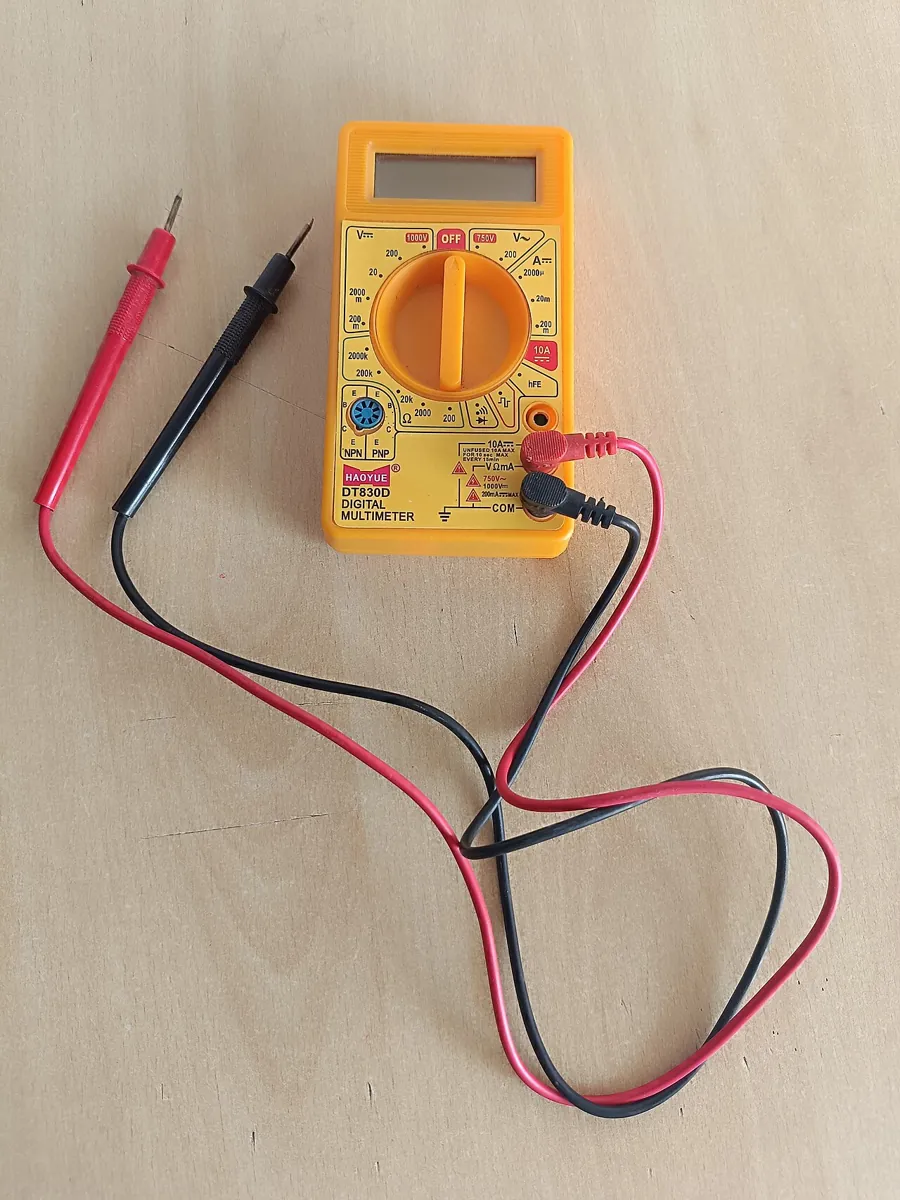
Ohm’s law is easy to check with a ₹300–₹600 multimeter, a 5 V USB supply (or the Uno’s 5 V pin), one LED and a few resistors.
- Build LED + 220 Ω on a breadboard from the Uno’s 5 V pin to GND. Measure the voltage across the LED and across the resistor — they should add up to about 5 V.
- Divide the resistor voltage by 220 to get the current. Compare with the 13–14 mA the lesson predicts for a red LED.
- Swap in 1 kΩ and repeat. The LED gets dimmer and the current drops to about 3 mA — Ohm’s law in your hand.
Debugging
Debugging: when it doesn’t work
| Symptom | Likely cause | Fix |
|---|---|---|
| LED never lights | LED in backwards (long leg = anode = +), or no return path to GND | Flip the LED; check the GND wire |
| LED very dim | Resistor far too big (e.g. 10 kΩ) or 3.3 V supply with a blue/white LED | Recalculate R with Vf; give enough headroom |
| LED flashed once and died | No resistor, or R rounded down far too much | Always use the next standard value up |
| Python result is 1000× off | Mixed mA and A | Convert to amps first (20 mA = 0.020 A) |
Think
Think about it
Think
Ankit says: “My LED is dim on 3.3 V. If I connect it to 5 V without any resistor it will just be brighter, right?” What is wrong with this thinking, and what should he do instead?
Experiment
Try it in the lab: Ohm drills for a status LED
Fifteen minutes, notebook open. You will solve for I, R and V in the browser Ohm’s Law Lab, then add the LED’s forward voltage by hand — exactly the calculation a lab senior would ask you to show before you wire anything.
Experiment
Ohm drills for a status LED
You will need
- Ohm’s Law Lab (below, runs in your browser)
- Notebook or a text file
- Optional: your Linux laptop to run `ohms_law.py` and `led_resistor.py`
Steps
- Open the Ohm’s Law Lab and choose **Solve for I**. Set V = 5.0 V and R = 250 Ω. Write down the current (you should see about 20 mA).
- Keep V = 5.0 V and move R to 500 Ω, then 1000 Ω. Write the three currents in a small table. What happens to I when R goes up?
- Now drag R down to 100 Ω. Read the tip line under the answer — note what it says once the current goes above 40 mA.
- Choose **Solve for R**. Set V = 5.0 V and I = 0.020 A (20 mA). Write down R (about 250 Ω). This is the drill *ignoring* the LED.
- Now include the LED: for a red LED with Vf ≈ 2.0 V, the resistor sees only 5.0 − 2.0 = 3.0 V. Set V = 3.0 V and I = 0.015 A. Write down R (about 200 Ω) and pick the next standard value up (220 Ω).
- Choose **Solve for V**. Set I = 0.015 A and R = 220 Ω. The answer (about 3.3 V) is the voltage across that resistor at 15 mA.
- Optional: run `led_resistor.py` and compare its “Red LED on a 5 V pin” lines with your step 5 answer.
- Finish with one sentence in your own words: why a simulation answer is a starting point and the datasheet is the final word.
Interactive · Ohm's Law Lab
Link voltage, current, and resistance with V = I × R. Numbers are educational — always check real datasheets and current limits.
I = 0.0200 A · 20.0 mA
Robot tip: LED + resistor on 5 V often targets ~10–20 mA.
At a fixed voltage, doubling R halves I. Ohm’s law is that simple — and it is why the resistor is the “tap” that controls how much current reaches your LED and your pin.
Knowledge check
Check your understanding
Knowledge check
1. Ohm’s law, in its core form, is…
2. The voltage stays fixed at 5 V and you increase the resistance from 220 Ω to 470 Ω. The current…
3. What is the safe way to connect a status LED to a logic pin?
4. A 5 V pin drives a red LED with Vf ≈ 2 V. You want about 15 mA. Which resistor calculation is correct?
5. 3 V sits across a resistor and 15 mA flows through it. How much heat does it make, roughly?
Mini assignment
Hands-on assignment
Mini assignment
Ohm intuition card + LED resistor sheet
Make a one-page card that explains voltage, current and resistance in your own words and shows a complete, checked resistor calculation for two robot status LEDs.
Deliverables
- Three plain-language lines: what voltage, current and resistance mean, using the water-tank, traffic or ceiling-fan picture
- Ohm’s law with its two rearrangements, plus the “triangle trick” sketch
- A resistor sheet for two LEDs of your choice (e.g. red on 5 V and green or blue on 3.3 V): supply, Vf (state where you got it), target mA, exact R, standard R picked, real current and resistor power
- Your table of currents from the experiment (R = 250, 500, 1000 Ω at 5 V) and one sentence on the pattern
- Output of `led_resistor.py` after you added one LED of your own (and one line explaining whether the result is sensible)
- A “never do this” list with at least three items (e.g. LED with no resistor, rounding R down, mixing mA and A)
Do this, step by step
- In the Ohm’s Law Lab, set 5 V and try R = 250, 500 and 1000 Ω. Write the three currents in a table.
- Copy the triangle trick into your notebook and write V = I × R, I = V ÷ R and R = V ÷ I under it.
- Pick a red LED on 5 V and a green LED on 3.3 V. For each, write Vf, target current, exact R, the standard R you pick, the real current and the resistor power.
- Add your own LED to
led_resistor.py, run it and paste the output. - Write your “never do this” list (three items).
Stuck? Hints, one at a time
- Hint 1: At 5 V: 250 Ω → 20 mA, 500 Ω → 10 mA, 1000 Ω → 5 mA. Doubling R halves the current.
- Hint 2: For the LED, subtract Vf first: (5 − 2.0) V ÷ 15 mA = 200 Ω, so pick 220 Ω (round up).
- Hint 3: With 220 Ω the real current is (5 − 2) ÷ 220 ≈ 13.6 mA, and resistor power is 3 V × 0.0136 A ≈ 41 mW — a ¼ W resistor is plenty.
- Hint 4: A blue or white LED (Vf about 3 V) on 3.3 V leaves only 0.3 V for the resistor — it will be dim and unpredictable. That is a good “why” line for your sheet.
Tip: explain it to a younger cousin with the terrace water tank. If you can say “the tank height is the volts, the water flowing is the milliamps, and the thin tap is the resistor”, and then do the 220 Ω calculation in front of them, you have understood this chapter.
Challenges (pick by level)
- 🟢 Easy: A 9 V battery and a 1 kΩ resistor — what current flows? (Answer in mA.)
- 🟡 Medium: Find the smallest standard resistor that keeps a red LED on 5 V under 10 mA, and its power.
- 🟠 Hard: Extend
ohms_law.pyto print the resistor power and warn when it is above 0.125 W (half of a ¼ W rating).
Next step
Look back: Lesson 1: Why Electronics Matters in Robotics. Next: Lesson 3: DC Circuits & Circuit Thinking. Related: Stage 0 — Power & Communication and Stage 1 — Math for Robotics.
Sources
Self-attested for now — keep artifacts in your lab notebook.
Complete
Today's goal
0 of 1 done today
Mark this lesson complete when you have worked the experiment, knowledge check, and assignment (even roughly).