
Kinematics & Inverse Kinematics · Lesson 01
Why Robots Need Kinematics
Est. 45–60 min
Why
Why this lesson matters
In Stage 7 you made each joint go to the angle you asked for. But a task is almost never “shoulder to 63°”. It is “pick the bottle from *here*”, “weld along *this* seam” or “touch *that* dot”. Kinematics is the geometry that connects joint angles to where the tool is — without worrying about forces, motors or PID. This whole stage is about that connection.
By the end of this lesson you will be able to: explain the difference between joint space and task space; say what forward kinematics (FK) and inverse kinematics (IK) do; run a small Python program that computes the tip of a 2-link arm and finds two (or zero) IK answers; and build a hand-moved ‘teach arm’ that prints its own tip position.
Concept
Joint space and task space
Two ways to describe the same arm
| Joint space | Task space | |
|---|---|---|
| What you list | Every joint angle: θ₁, θ₂, … | Where the tool is (x, y, z) and which way it points |
| Who speaks it | Motors, encoders, your Stage 7 PID loops | People, cameras, CAD drawings, the task itself |
| Example | shoulder 30°, elbow 60° | pen tip at x = 8.66 cm, y = 13.00 cm |
Forward kinematics (FK) goes from joint space to task space: “If the joints are at these angles, where is the tip?” For a normal (serial) arm, FK always has exactly one answer — you just multiply out the geometry.
Inverse kinematics (IK) goes the other way: “I want the tip *there*; which joint angles do it?” IK is harder. There may be two answers (elbow up or elbow down), many answers, or none at all if the point is out of reach. A general six-joint arm can have up to 16 IK answers for one pose.
The 2-link arm we will use
Look at an arm from the top, like a SCARA robot: a shoulder joint, a link of length L1 = 10 cm, an elbow joint and a second link of L2 = 8 cm. θ₁ is the shoulder angle from the x axis, and θ₂ is the elbow angle measured from the first link. The tip is at:
x = L1·cos(θ₁) + L2·cos(θ₁ + θ₂)
y = L1·sin(θ₁) + L2·sin(θ₁ + θ₂)
Read it as two arrows added together: the first link points along θ₁, and the second link points along θ₁ + θ₂ (its own angle plus the shoulder’s). Every FK you meet in this stage — including the full 6DOF arm — is this same idea with more links and in 3D.

What kinematics is — and is not
- Is: geometry of positions and orientations of links, joints and the tool. Later: workspace, singularities and velocities.
- Is not: forces, torques, motor currents or PID gains. That is dynamics and control (Stage 7).
- Works together with control: IK turns a target into joint angles; your Stage 7 loops make the joints reach them.
Visual
Visualise it: one chain, one tip
Move θ₁–θ₃ and watch the tip move. Each set of joint angles gives one tip position — that is forward kinematics.
Interactive · FK chain visualizer (3R planar educational)


Simplified 3R planar stand-in for Base→J1→J2→J3→EE. Full 6DOF adds wrist RPY on top of this position chain.
EE x
153.4
EE y
35.8
ᵇTₑ (planar) calculator
| 0.966 | -0.259 | 0.000 | 157.02 |
| 0.259 | 0.966 | 0.000 | 20.55 |
| 0.000 | 0.000 | 1.000 | 0.00 |
| 0.000 | 0.000 | 0.000 | 1.000 |
Code lab
Code lab: FK and a first taste of IK
why_kinematics.py has two small functions. fk(t1, t2) uses the two formulas above. ik(x, y) uses the law of cosines to find the elbow angle, then the shoulder angle — once with the elbow bent one way and once the other way. Run it with python3 why_kinematics.py.
# why_kinematics.py - joint space vs task space on a 2-link planar arm (top view, like a SCARA).
# Forward kinematics (FK): joint angles -> where the tip is.
# Inverse kinematics (IK): where you want the tip -> joint angles (0, 1 or 2 answers here).
import math

L1, L2 = 10.0, 8.0          # link lengths in cm (shoulder->elbow, elbow->tip)


def fk(t1_deg, t2_deg):
    """Tip (x, y) in cm. t1 = shoulder angle from the x axis, t2 = elbow angle relative to link 1."""
    t1, t2 = math.radians(t1_deg), math.radians(t2_deg)
    x = L1 * math.cos(t1) + L2 * math.cos(t1 + t2)
    y = L1 * math.sin(t1) + L2 * math.sin(t1 + t2)
    return x, y


def ik(x, y):
    """All (t1, t2) in degrees that put the tip at (x, y). Simple closed form for 2 links."""
    c2 = (x * x + y * y - L1 * L1 - L2 * L2) / (2 * L1 * L2)
    if abs(c2) > 1:
        return []                                   # out of reach
    answers = []
    for sign in (+1, -1):                          # elbow one way, then the other
        t2 = sign * math.acos(c2)
        t1 = math.atan2(y, x) - math.atan2(L2 * math.sin(t2), L1 + L2 * math.cos(t2))
        answers.append((math.degrees(t1), math.degrees(t2)))
    return answers


print("1) FK: one set of joint angles gives exactly one tip position")
print(f"{'shoulder':>9} {'elbow':>7}  ->  {'x cm':>6} {'y cm':>6}")
for t1, t2 in ((0, 0), (90, 0), (30, 60), (45, -90), (60, 90)):
    x, y = fk(t1, t2)
    print(f"{t1:>8}° {t2:>6}°  ->  {x:>6.2f} {y:>6.2f}")

print("\n2) IK: a tip target can have two answers, or none")
for target in ((12.0, 6.0), (18.0, 0.0), (25.0, 0.0)):
    sols = ik(*target)
    if not sols:
        print(f"target {target}: no answer - farther than L1 + L2 = {L1 + L2:.0f} cm")
        continue
    uniq = {(round(a, 2), round(b, 2)) for a, b in sols}
    for a, b in sorted(uniq):
        x, y = fk(a, b)
        print(f"target {target}: shoulder {a:7.2f}°, elbow {b:7.2f}°  (check FK -> {x:.2f}, {y:.2f})")

print("\n3) Why small joint errors matter: shoulder off by 1° with the arm stretched out")
x0, y0 = fk(0, 0)
x1, y1 = fk(1, 0)
print(f"tip moves {math.dist((x0, y0), (x1, y1)):.2f} cm for 1° at the shoulder (reach {L1 + L2:.0f} cm)")
Output (run with python3 why_kinematics.py)
1) FK: one set of joint angles gives exactly one tip position
 shoulder   elbow  ->    x cm   y cm
       0°      0°  ->   18.00   0.00
      90°      0°  ->    0.00  18.00
      30°     60°  ->    8.66  13.00
      45°    -90°  ->   12.73   1.41
      60°     90°  ->   -1.93  12.66

2) IK: a tip target can have two answers, or none
target (12.0, 6.0): shoulder   -9.83°, elbow   84.26°  (check FK -> 12.00, 6.00)
target (12.0, 6.0): shoulder   62.96°, elbow  -84.26°  (check FK -> 12.00, 6.00)
target (18.0, 0.0): shoulder    0.00°, elbow    0.00°  (check FK -> 18.00, 0.00)
target (25.0, 0.0): no answer - farther than L1 + L2 = 18 cm

3) Why small joint errors matter: shoulder off by 1° with the arm stretched out
tip moves 0.31 cm for 1° at the shoulder (reach 18 cm)Try it: drag the target and watch the solver find joint angles. Look for points with two answers and points with none.
Interactive · IK solver lab (analytical 2R — educational)


Workflow: target → IK → joints → FK verify → residual. Not a black box — elbow-up/down closed form. Not full 6DOF analytic IK.
Status · ok
2 analytical solution(s) (2R planar).
θ₁
-12.2°
θ₂
92.3°
FK err
0.000
Real world
Kinematics in the real world
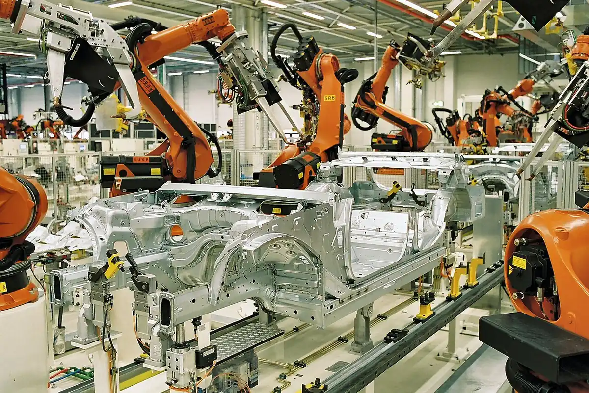
- Car factories: a spot-welding robot is given weld points in the car’s coordinates; IK turns each point into joint angles.
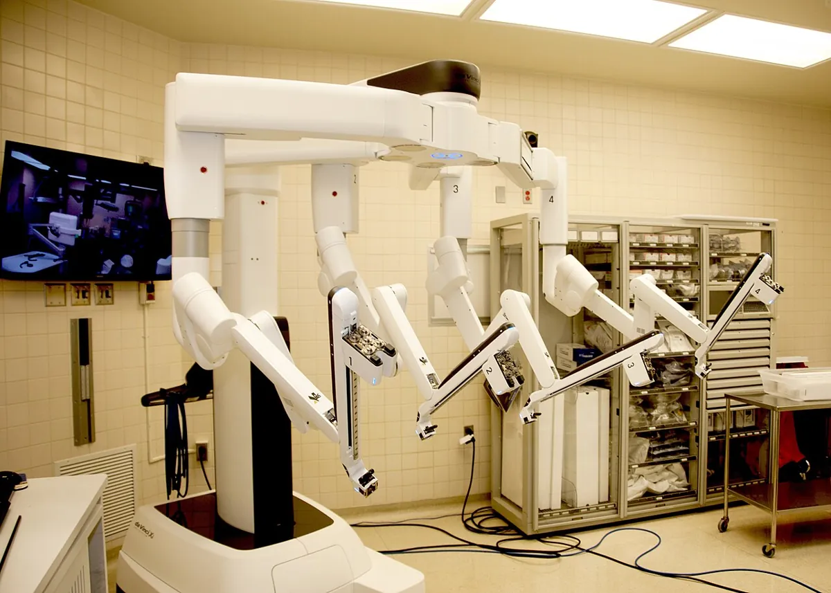
- Surgery: in a surgical robot the surgeon moves hand controls in task space and the system works out the joint motions of the instrument arms.
- Pick-and-place: a camera finds a part at (x, y); IK decides how the arm reaches it.
- Animation and games: IK places a character’s foot on the ground or hand on a door handle.
Bench build
Bench build: a teach arm that knows where its tip is
Build a passive 2-link arm from thick card or ice-cream sticks, with a 10 kΩ potentiometer at the shoulder and another at the elbow (the knob shafts are the joints). You move it by hand; teach_arm_fk.ino reads both angles and prints the tip position using FK. Put graph paper under it and check the numbers with a ruler.
| From | To | Note |
|---|---|---|
| Each pot, outer pin 1 | Arduino 5 V | — |
| Each pot, outer pin 2 | Arduino GND | — |
| Shoulder pot, middle pin | A0 | Wiper = angle signal |
| Elbow pot, middle pin | A1 | Wiper = angle signal |
Build the arm
Link 1 = 10 cm from shoulder shaft to elbow shaft, link 2 = 8 cm from elbow shaft to a pen hole or pointer. Fix the shoulder pot to a heavy base.
Calibrate
Upload, open Serial Monitor at 115200. Put each joint at 0° and then 90° (use a set square) and note
raw_shandraw_el. Type them intoSH_0,SH_90,EL_0,EL_90and upload again.Check FK
Move the tip to a grid point, e.g. (12, 6). Does the printed x, y match within about 0.5 cm?
Find both answers
Put the tip on (12, 6) with the elbow bent one way, then the other. Compare the angles with Part 2 of the Python output.
// teach_arm_fk.ino - a "teach arm" that shows forward kinematics live.
// Build a 2-link arm from card or ice-cream sticks with a potentiometer at each joint.
// You move the arm by hand; the Arduino reads the two joint angles and prints where the tip is.
// No motors here. If you later add servos, power them from a SEPARATE 5-6 V supply,
// never from an Arduino pin, and join the grounds.
// Wiring: each 10 k pot -> outer pins to 5 V and GND, middle (wiper) to A0 (shoulder) / A1 (elbow).
const float L1 = 10.0, L2 = 8.0;          // link lengths in cm - measure YOUR arm
// Calibrate: the pot reading at 0 deg and at 90 deg for each joint (read them from Serial first)
const int SH_0 = 512, SH_90 = 800;        // CHANGE THESE after calibration
const int EL_0 = 512, EL_90 = 800;

float toDeg(int raw, int at0, int at90) {
  return (raw - at0) * 90.0 / (at90 - at0);
}

void setup() {
  Serial.begin(115200);
  Serial.println(F("raw_sh,raw_el,shoulder_deg,elbow_deg,x_cm,y_cm"));
}

void loop() {
  int rs = analogRead(A0), re = analogRead(A1);
  float t1 = toDeg(rs, SH_0, SH_90), t2 = toDeg(re, EL_0, EL_90);
  float a = radians(t1), b = radians(t1 + t2);
  float x = L1 * cos(a) + L2 * cos(b);     // forward kinematics, same as the Python lab
  float y = L1 * sin(a) + L2 * sin(b);
  Serial.print(rs); Serial.print(',');
  Serial.print(re); Serial.print(',');
  Serial.print(t1, 1); Serial.print(',');
  Serial.print(t2, 1); Serial.print(',');
  Serial.print(x, 2); Serial.print(',');
  Serial.println(y, 2);
  delay(200);
}Debugging
Debugging FK
| Symptom | Likely cause | Fix |
|---|---|---|
| Tip position is nonsense | Degrees passed to cos/sin | Use math.radians() / radians() |
| x and y swapped or mirrored | Angle measured from the wrong axis or the wrong direction | Write down where 0° is and which way is positive |
| Elbow works only when the shoulder is at 0° | Used θ₂ instead of θ₁ + θ₂ for link 2 | Link 2’s direction is θ₁ + θ₂ |
| Bench: error grows near the ends of the pot | Pot is not perfectly linear, or calibration points too close | Calibrate at 0° and 90°, keep within that range |
| Bench: numbers jump by ±1° | ADC noise | Average a few readings (Stage 7, Lesson 12) |
Think
Think about it
Think
Kabir’s arm can reach the dot at (12, 6) with the elbow bent left or bent right. Tara puts a cup just to the left of the dot. Which answer should the robot use, and who decides?
Experiment
Try it in the lab
About 30 minutes with the Python file and the browser labs (and the optional teach arm).
Experiment
Joint space vs task space
You will need
- `why_kinematics.py` and Python 3
- FK chain visualiser and IK solver lab (in your browser)
- Graph paper and a ruler
- Optional: Arduino UNO, two 10 kΩ potentiometers, card or sticks, jumper wires
Steps
- Run `why_kinematics.py` and copy Part 1 into your notebook. Pick one row and check x, y with a calculator.
- Add your own FK row: shoulder 120°, elbow −60°. Predict roughly where the tip is before you run it.
- Add the targets (5, 5) and (0, 18) to Part 2. How many answers does each have?
- Change L2 to 10 cm. Which targets that were out of reach are now reachable?
- In the IK solver lab, find a point with two answers and a point with none.
- Optional: calibrate the teach arm and check three grid points against the printed x, y.
Interactive · FK chain visualizer (3R planar educational)
Simplified 3R planar stand-in for Base→J1→J2→J3→EE. Full 6DOF adds wrist RPY on top of this position chain.
EE x
153.4
EE y
35.8
ᵇTₑ (planar) calculator
| 0.966 | -0.259 | 0.000 | 157.02 |
| 0.259 | 0.966 | 0.000 | 20.55 |
| 0.000 | 0.000 | 1.000 | 0.00 |
| 0.000 | 0.000 | 0.000 | 1.000 |
FK always gives one tip. IK gives two answers inside the reach, one answer at full stretch, and none outside. Longer links reach farther but turn small joint errors into larger tip errors.
Knowledge check
Check your understanding
Knowledge check
1. Kinematics mainly relates…
2. Forward kinematics (FK) maps…
3. For the 2-link arm (L1 = 10 cm, L2 = 8 cm), how many IK answers does the target (12, 6) have?
4. Why does the target (25, 0) have no IK answer?
5. In the FK formula, the second link points along…
6. Your FK output looks random. The most likely beginner bug is…
7. With the arm stretched out to 18 cm, a 1° shoulder error moves the tip by about…
Mini assignment
Hands-on assignment
Mini assignment
Joint space vs task space card
Make a one-page card that explains FK and IK to a friend who has never heard of them, using your own 2-link numbers.
Deliverables
- A sketch of the 2-link arm with θ₁, θ₂, L1, L2 and the x, y axes labelled.
- Three FK rows of your own, computed by hand and checked with `why_kinematics.py`.
- One target with two IK answers, one at full stretch, and one out of reach — with a sketch of the two-answer case.
- Two sentences: what kinematics covers in this stage and what it does not (forces, motors, PID).
- Optional: three teach-arm readings next to ruler measurements, and the error for each.
Do this, step by step
- Run
python3 why_kinematics.pyand copy Part 1. Pick one row and check x and y with a calculator using x = L1·cos θ₁ + L2·cos(θ₁ + θ₂). - Add the FK row shoulder 120°, elbow −60° to the code. Write your guess for the tip first, then run and compare.
- Add the targets (5, 5) and (0, 18) to Part 2 and note how many IK answers each has. Then try (1, 0) — why is it also unreachable?
- In the IK solver lab, drag the target until you find one point with two answers and one with none. Sketch both on your card.
- Draw the 2-link arm with θ₁, θ₂, L1, L2 and the axes labelled, and finish the card with your two sentences on what kinematics does and does not cover.
Stuck? Hints, one at a time
- For FK, convert degrees to radians first; link 2 points along θ₁ + θ₂, not θ₂.
- A target closer than L1 − L2 = 2 cm or farther than L1 + L2 = 18 cm has no answer.
- Two answers are mirror images about the line from the shoulder to the target.
Challenges (pick by level)
- 🟢 Easy: Compute FK by hand for shoulder 0°, elbow 90°. Check with the code.
- 🟢 Easy: List three tasks from daily life and write whether each is described in joint space or task space.
- 🟡 Medium: Change the code to print a grid of targets from x = −18 to 18 and mark each one as 0, 1 or 2 answers.
- 🟠 Hard-ish: Add a joint limit (elbow between −90° and +90° only) to
ik()and see which answers disappear. - 🔴 Hard: Add a third link (L3 = 4 cm) to
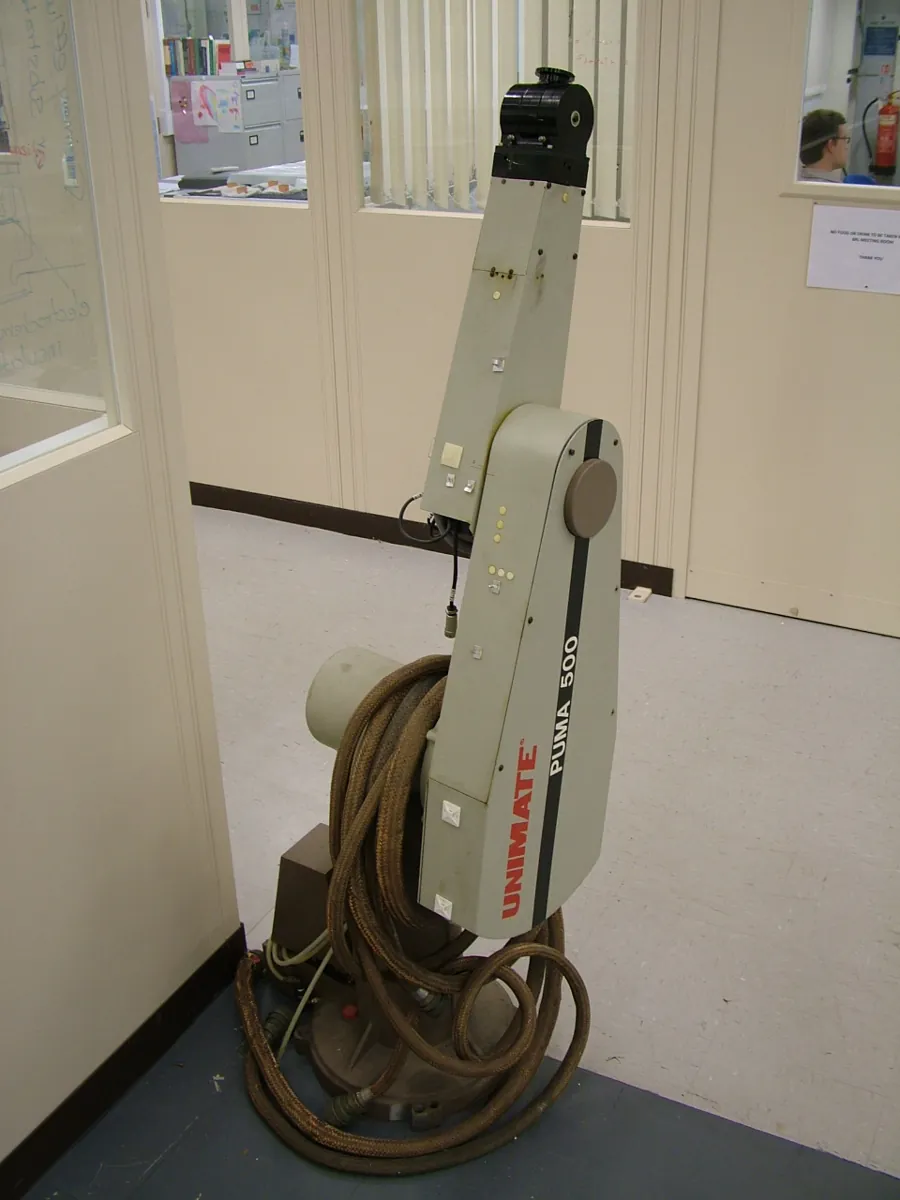
fk(). Why doesik()now have infinitely many answers for most targets? - ⚫ Research: Read how the PUMA or a SCARA robot is described in a robotics textbook and list its joints and link lengths.
Next step
To talk about ‘where’ precisely, you need to say *measured from where*. In Lesson 2 — Coordinate Frames & Reference Frames you will give the base, each link and the tool their own frame.
Look back: Stage 7: Capstone: Tune a Robot Joint and Stage 1: Trigonometry for Robots. Next: Lesson 2: Coordinate Frames & Reference Frames. Related: Stage 6 — 6DOF Arm and Stage 9 — Trajectory Planning.
Sources
- Wikipedia — Robot kinematics — kinematics as geometry of kinematic chains; forward vs inverse kinematics; workspace; up to 16 IK solutions for a general 6R arm.
- Wikipedia — Inverse kinematics — why IK matters (tasks at the end effector, control at the joints); analytical vs numerical solutions.
- Photos and diagram: Wikimedia Commons (credits under each image).
Self-attested for now — keep artifacts in your lab notebook.
Complete
Today's goal
0 of 1 done today
Mark this lesson complete when you have worked the experiment, knowledge check, and assignment (even roughly).