
Robotics Fundamentals · Lesson 06
Sensors & Proprioception
Est. 55–70 min
Why
Why a robot must feel its own body before it can see the world
Robots have two kinds of senses. Proprioception measures the robot itself: joint angles, wheel turns, motor current, its own tilt and turning rate. Exteroception measures the world: distances, images, sounds, touch. OSHA lists sensors as part of every industrial robot system, including tilt and navigation sensors. Without proprioception, a robot cannot close a control loop on its joints (Lesson 8) or know where its tool is (Lesson 10). Without exteroception, it cannot react to anything new.
By the end you will be able to: sort any sensor into proprioceptive or exteroceptive; explain how a potentiometer, an incremental optical encoder and an absolute magnetic encoder measure a joint angle; compute an encoder’s resolution in degrees per count; decode quadrature signals to find direction; use an accelerometer to measure tilt and know why it fails when moving; explain why a gyro’s angle drifts; and build a real joint-angle sensor with a potentiometer and a limit switch.
Concept
Proprioception and exteroception in plain words
Think of an auto-rickshaw driver. The meter counts wheel turns to know how far the rickshaw has gone — that’s proprioception (odometry). The driver’s eyes watch the traffic — exteroception. If the meter is wrong, the fare is wrong even if the driver sees perfectly. If the driver closes his eyes, the meter alone will crash the rickshaw. A good robot, like a good driver, uses both.
Two families of sense
| Sensor | Measures | Family | Robot use |
|---|---|---|---|
| Potentiometer on a joint | Joint angle (as a voltage) | Proprioceptive | Hobby servos, simple arms |
| Optical / magnetic encoder | Joint or wheel angle (as counts) | Proprioceptive | Industrial joints, wheels, smart servos |
| Motor current sense | How hard the motor is working | Proprioceptive | Collision and overload detection |
| IMU (accelerometer + gyro) | The body’s own acceleration and turning rate | Proprioceptive | Balancing, drones, mobile robots |
| Limit switch | “Joint at end of travel” | Proprioceptive (about the robot’s own joint) | Homing, safety stops |
| Ultrasonic / IR range | Distance to things | Exteroceptive | Obstacle avoidance (Lesson 7) |
| Camera, depth camera, LiDAR | Images, depth, 3-D shape of the room | Exteroceptive | Mapping, picking, navigation |
Measuring a joint angle: three ways
Potentiometer
A resistor track with a wiper that turns with the joint. With the ends on 5 V and GND, the wiper voltage is proportional to the angle. An Arduino’s 10-bit ADC turns it into 0–1023 (Stage 4, Lesson 8). Cheap and absolute — it is what hobby servos use inside — but it wears and is noisy.
Incremental optical encoder
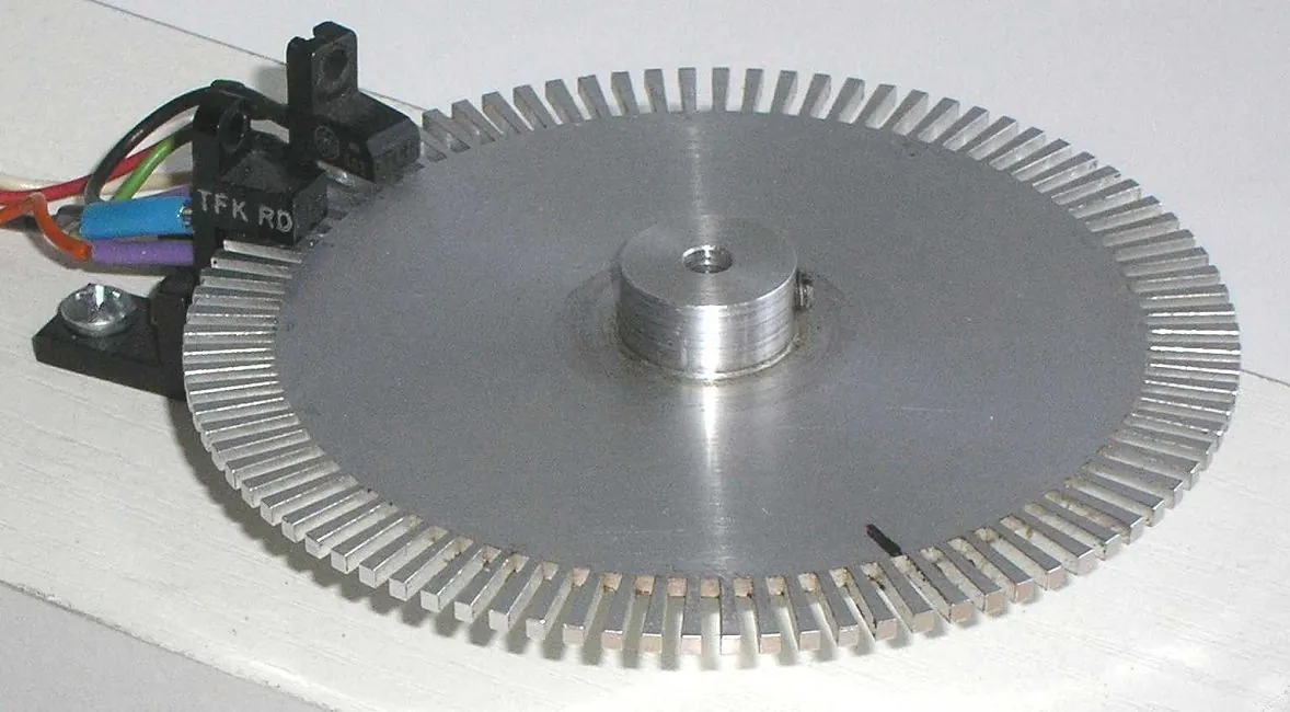
A slotted disc spins between an LED and light sensors, making pulses. Two sensors placed a quarter-slot apart (channels A and B, “quadrature”) let you count pulses *and* tell direction. It only counts change, so after power-on it must find a reference (home) position.
Absolute encoder
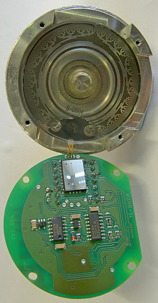
Gives a unique reading for every angle. The opened Gray-code encoder in this chapter does it optically; the ROBOTIS XL430-W250 uses a contactless 12-bit magnetic encoder (an AS5601), so it reads 4096 positions per turn and knows its angle at power-up.
resolution (° per count) = 360° ÷ counts per revolution
- 12-bit absolute: 360 ÷ 4096 ≈ 0.088°. 1000-line incremental read with ×4 quadrature: 360 ÷ 4000 = 0.09°. Potentiometer with a 10-bit ADC over a typical ~270° travel: about 270 ÷ 1023 ≈ 0.26°.
Sensing the body: accelerometers and gyros
SparkFun’s guides explain both. An accelerometer measures acceleration in m/s² or in g (1 g ≈ 9.8 m/s²); it senses static forces like gravity and dynamic ones like vibration and movement. When the robot is still, the gravity vector tells you which way is down — so you can compute tilt. A gyroscope measures angular velocity in degrees per second (a wheel spinning once a second is 360 °/s). Gyros only measure angular velocity — to get an angle you must add up (integrate) the readings over time.
pitch = atan2(aₓ, √(a_y² + a_z²)) angle_gyro = Σ (rate × Δt)
- The tilt formula is valid only when the robot is not accelerating. The gyro sum grows any small bias into a big error: a bias of 0.5 °/s (an example value) becomes 30° after one minute.
Visual
Visualise it: sensing the world outside
This is **exteroception**: the sensor measures distance to something outside the robot. Move the object and watch the reading change. Then ask: what would the robot need to know about *itself* to use this reading?
Interactive · Distance-sensor decision
Measured distance
80 cm
Policy: distance ≤ stop → STOP · else ≤ turn → TURN · else FORWARD. Real robots add hysteresis to avoid chatter.
Code lab
Code lab: encoders, quadrature, tilt and drift
Five small experiments in one script: encoder resolution, converting a 12-bit reading into degrees, decoding a quadrature A/B sequence, computing tilt from an accelerometer, and watching a gyro’s angle drift from a small bias. Run it with python3 joint_sensors.py.
"""joint_sensors.py - proprioception in numbers: encoder counts, quadrature direction,
accelerometer tilt and gyro drift. Pure Python simulation - no hardware needed."""
import math

# --- 1. Encoder counts -> angle ---
print("== 1. Encoder resolution ==")
for name, cpr in [("hobby pot + 10-bit ADC over ~270 deg", 1024 * 360 / 270), ("12-bit magnetic encoder", 4096), ("1000-line optical, x4 quadrature", 4000)]:
    print(f"{name:38s} {cpr:7.0f} counts/rev -> {360/cpr:.3f} deg per count")
counts = 1536
print(f"XL430-style reading {counts} of 4096 -> {counts*360/4096:.1f} deg")

# --- 2. Quadrature: which way did it turn? ---
print("\n== 2. Quadrature decoding (A, B) ==")
ORDER = [(0, 0), (1, 0), (1, 1), (0, 1)]   # one direction steps through this cycle
def decode(states):
    pos = 0
    for prev, cur in zip(states, states[1:]):
        step = (ORDER.index(cur) - ORDER.index(prev)) % 4
        pos += {0: 0, 1: +1, 3: -1}.get(step, 0)
    return pos
fwd = [(0, 0), (1, 0), (1, 1), (0, 1), (0, 0), (1, 0)]
rev = list(reversed(fwd))
print("forward sequence ->", decode(fwd), "counts")
print("reverse sequence ->", decode(rev), "counts")

# --- 3. Tilt from an accelerometer at rest (gravity only) ---
print("\n== 3. Accelerometer tilt (robot standing still) ==")
for ax, ay, az in [(0.0, 0.0, 9.81), (4.905, 0.0, 8.496), (9.81, 0.0, 0.0)]:
    pitch = math.degrees(math.atan2(ax, math.hypot(ay, az)))
    print(f"a = ({ax:5.2f}, {ay:4.2f}, {az:5.2f}) m/s^2 -> pitch {pitch:5.1f} deg")

# --- 4. Gyro: integrate angular rate, watch a small bias grow ---
print("\n== 4. Gyro drift (true rate 0, bias 0.5 deg/s, 100 Hz) ==")
angle, dt, bias = 0.0, 0.01, 0.5
for step in range(1, 6001):
    angle += (0.0 + bias) * dt
    if step in (100, 1000, 6000):
        print(f"after {step*dt:5.1f} s the gyro thinks we turned {angle:5.1f} deg")
print("fix: re-zero at rest, or fuse with the accelerometer / an encoder")

# --- 5. Proprioception vs exteroception ---
print("\n== 5. Which kind of sense? ==")
for s, kind in [("joint encoder", "proprio"), ("servo pot", "proprio"), ("motor current", "proprio"),
                ("IMU on the body", "proprio"), ("ultrasonic range", "extero"), ("camera", "extero"), ("LiDAR", "extero")]:
    print(f"{s:16s} -> {kind}ception")
Output (run with python3 joint_sensors.py)
== 1. Encoder resolution ==
hobby pot + 10-bit ADC over ~270 deg      1365 counts/rev -> 0.264 deg per count
12-bit magnetic encoder                   4096 counts/rev -> 0.088 deg per count
1000-line optical, x4 quadrature          4000 counts/rev -> 0.090 deg per count
XL430-style reading 1536 of 4096 -> 135.0 deg

== 2. Quadrature decoding (A, B) ==
forward sequence -> 5 counts
reverse sequence -> -5 counts

== 3. Accelerometer tilt (robot standing still) ==
a = ( 0.00, 0.00,  9.81) m/s^2 -> pitch   0.0 deg
a = ( 4.91, 0.00,  8.50) m/s^2 -> pitch  30.0 deg
a = ( 9.81, 0.00,  0.00) m/s^2 -> pitch  90.0 deg

== 4. Gyro drift (true rate 0, bias 0.5 deg/s, 100 Hz) ==
after   1.0 s the gyro thinks we turned   0.5 deg
after  10.0 s the gyro thinks we turned   5.0 deg
after  60.0 s the gyro thinks we turned  30.0 deg
fix: re-zero at rest, or fuse with the accelerometer / an encoder

== 5. Which kind of sense? ==
joint encoder    -> proprioception
servo pot        -> proprioception
motor current    -> proprioception
IMU on the body  -> proprioception
ultrasonic range -> exteroception
camera           -> exteroception
LiDAR            -> exteroception
Drag the A0 slider: this is your potentiometer joint sensor turning a voltage into a 10-bit number (Stage 4, Lesson 8).
Interactive · GPIO / ADC / PWM Lab
Fake MCU board for digital out, analog in, and PWM duty. Browser-only — never talks to real USB/serial/hardware.
GPIO D7
Good for LEDs / logic — not motors.
ADC A0 (10-bit)
raw 512 → 2.50 V
Pot / distance proxy → robot perception.
PWM D9
duty 40%
PWM → driver → motor — never GPIO-direct.
board@sim ~ pins: D7=0 A0=512 D9=40% · educational MCU only
Real world
Robot senses in real machines
- Industrial arm joints: an encoder behind every motor (Modern Robotics shows the encoder, motor, gearhead and bearing stacked in each joint).
- Smart servos: the XL430-W250 reads a 12-bit absolute magnetic encoder and also has position-limit and temperature-limit settings.
- Mobile robots: wheel encoders for odometry plus an IMU; the TurtleBot3 Burger lists a 3-axis gyro and 3-axis accelerometer.
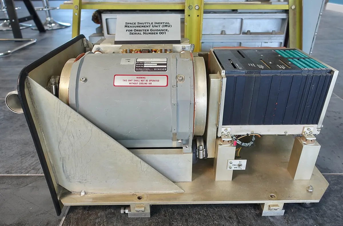
- Spacecraft: the Space Shuttle used inertial measurement units of gyros and accelerometers for guidance.
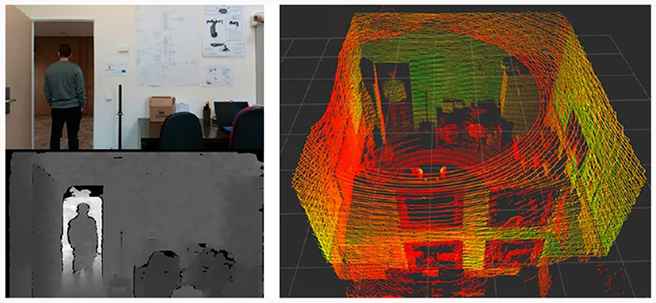
- Service robots: RGB-D cameras and LiDAR give exteroceptive pictures of a whole room.
Bench build
Bench build: a potentiometer joint sensor with a limit switch
Turn your cardboard elbow (Lesson 3) into a measured joint. A potentiometer’s shaft becomes the elbow pin; a push-button becomes the end-of-travel limit switch.
Mount the pot
Fix a 10 kΩ rotary potentiometer’s body to the upper-arm strip and glue a knob or lever to its shaft that turns with the forearm strip.
Wire the pot
Outer legs to 5 V and GND, middle (wiper) leg to A0.
Wire the switch
Push-button between pin 2 and GND. The sketch uses the internal pull-up, so pressed reads LOW. Place it where the forearm hits it at the end of travel.
Upload
Upload
pot_joint_sensor.ino, open the Serial Monitor at 9600 baud and move the elbow.Calibrate
Hold the forearm straight (0°) and at a right angle (90°) using a protractor. Write the counts at each. Compute your own degrees per count and put it in
DEG_PER_COUNT.Check
Move to 45° by protractor. Does the reading agree within a couple of degrees?
// pot_joint_sensor.ino - proprioception on the bench: a potentiometer reads a joint angle,
// a limit switch says "end of travel". Pot: ends to 5V and GND, wiper to A0.
// Switch: one leg to pin 2, other leg to GND (internal pull-up, so pressed = LOW).
const int POT_PIN = A0;
const int LIMIT_PIN = 2;
const float DEG_PER_COUNT = 270.0 / 1023.0;   // set from YOUR pot's electrical angle

void setup() {
  Serial.begin(9600);
  pinMode(LIMIT_PIN, INPUT_PULLUP);
}

void loop() {
  long sum = 0;
  for (int i = 0; i < 8; i++) sum += analogRead(POT_PIN);   // average 8 readings
  int counts = sum / 8;
  float angle = counts * DEG_PER_COUNT;
  bool atLimit = digitalRead(LIMIT_PIN) == LOW;
  Serial.print("counts=");
  Serial.print(counts);
  Serial.print("  angle=");
  Serial.print(angle, 1);
  Serial.println(atLimit ? "  LIMIT!" : "");
  delay(100);   // 10 readings per second
}Debugging
Debugging joint sensors
| Symptom | Likely cause | Fix |
|---|---|---|
| Reading jumps by several counts at rest | Noise on the analog line | Average readings (the sketch averages 8); short wires; a small capacitor from wiper to GND |
| Angle goes the wrong way | Pot ends swapped | Swap 5 V and GND legs, or use 1023 − counts |
| Reading stuck at 0 or 1023 | Wiper not connected, or the pot turned past its travel | Check the middle leg; mount the pot so the joint stays inside its travel |
| Incremental encoder count wrong after reset | Incremental encoders don’t remember position | Home to a limit switch at start-up |
| Quadrature counts only one way or double | A and B swapped or noisy edges | Swap A/B; debounce or use hardware interrupts |
| IMU tilt jumps when the robot moves | Accelerometer feels motion, not just gravity | Use tilt only when still, or fuse with the gyro |
| IMU heading slowly turns by itself | Gyro bias drift | Re-zero at rest; fuse with another sensor |
Think
Think about it
Think
Arjun’s servo arm has no extra sensors, only the potentiometers inside the servos. Meera says, “Then it already has proprioception.” Arjun says, “But my code can’t read those pots.” Who is right, and what would you add so the *Arduino* knows the real joint angle?
Experiment
Try it in the lab: build a joint-angle sensor
Thirty minutes with the distance-sensor visual, the sensor script and the potentiometer bench build.
Experiment
Build a joint-angle sensor
You will need
- Distance sensor visual (below, runs in your browser)
- 10 kΩ potentiometer, push-button, Arduino, jumper wires
- Protractor
- Optional: `joint_sensors.py`
Steps
- In the visual, move the object. Write whether this sensor is proprioceptive or exteroceptive, and one thing it cannot tell the robot.
- Run `joint_sensors.py`. Write the resolution of each encoder and the gyro error after 60 s.
- Build the pot joint sensor and calibrate it at 0° and 90°.
- Measure 45°, 30° and 120° with both protractor and sensor. Write the errors.
- Leave the joint still for one minute and write the largest jump in counts. That is your noise level.
Interactive · Distance-sensor decision
Measured distance
80 cm
Policy: distance ≤ stop → STOP · else ≤ turn → TURN · else FORWARD. Real robots add hysteresis to avoid chatter.
Proprioception tells the robot about itself; exteroception tells it about the world. Every sensor has a resolution, noise and a failure mode — measure them before you trust it.
Knowledge check
Check your understanding
Knowledge check
1. Proprioception means sensing…
2. Which of these is exteroceptive?
3. A 12-bit absolute encoder has a resolution of about…
4. Why do incremental encoders need homing after power-up?
5. Two encoder channels A and B a quarter-cycle apart (quadrature) let you…
6. A gyroscope directly measures…
7. Why does a gyro-only angle drift?
8. An accelerometer gives a good tilt reading when…
9. The XL430-W250 measures its own angle with…
10. In `pot_joint_sensor.ino`, a pressed limit switch reads LOW because…
Mini assignment
Hands-on assignment
Mini assignment
Give your arm a sense of its own elbow
Build and calibrate a potentiometer joint sensor with a limit switch, measure its noise and accuracy, and sort every sensor on a real robot into proprioceptive and exteroceptive.
Deliverables
- A photo of your sensor joint and your wiring sketch.
- A calibration table: protractor angle vs raw counts vs computed angle, for at least five angles, with the error.
- Your noise measurement (largest jump at rest) and one change that reduced it.
- A sensor list for one real robot (TurtleBot3, a robot vacuum or your arm) split into proprioceptive and exteroceptive.
Do this, step by step
- Mount a potentiometer as a joint sensor and wire it to A0 (outer legs to 5 V and GND, wiper to A0); add a limit switch on a digital pin with INPUT_PULLUP.
- Flash
pot_joint_sensor.inoand open the Serial Monitor at the baud rate in the sketch. - Calibrate: set the joint to at least five protractor angles and record raw counts and computed angle; work out the error at each.
- Leave the joint still for 30 s and note the largest jump in counts; add averaging (or a 0.1 µF capacitor at A0) and measure again.
- Run
joint_sensors.py, then list every sensor on one real robot and split them into proprioceptive and exteroceptive.
Stuck? Hints, one at a time
- Hint 1: If the Serial Monitor shows nothing, check the baud rate is 9600 and the right port is chosen.
- Hint 2: If counts don’t change, check the wiper is the middle leg and goes to A0.
- Hint 3: For calibration: degrees per count = (90 − 0) ÷ (counts at 90° − counts at 0°).
- Hint 4: If the sign is wrong, the counts go down as the angle goes up — use a negative scale or swap the outer legs.
Challenges (pick by level)
- 🟢 Easy: Compute the resolution of a 14-bit encoder in degrees.
- 🟢 Easy: Sort ten sensors in your phone into proprioceptive (about the phone) and exteroceptive (about the world).
- 🟡 Medium: Add an offset so your sketch prints 0° when the forearm is straight, whatever the raw count.
- 🟡 Medium: In the script, add Gaussian noise to the accelerometer and compute the tilt 100 times. What is the spread?
- 🟠 Hard-ish: Write a complementary filter in Python: angle = 0.98 × (angle + gyro × dt) + 0.02 × accel_angle. Feed it biased gyro data and noisy accelerometer data. Does it drift?
- 🔴 Hard: Wire a real quadrature encoder (or two push-buttons as A and B) and count with interrupts on pins 2 and 3.
- ⚫ Expert: Read the XL430-W250 e-manual control table and explain how its Min/Max Position Limit and Temperature Limit registers protect a joint. Which would you set first on a new arm, and to what?
Next step
The robot can now sense. In Lesson 7 — Sense–Plan–Act Loop you put sensing, deciding and acting into one repeating loop — and learn what to do when a sensor stops answering.
Look back: Lesson 5: Actuators & Transmissions. Next: Lesson 7: Sense–Plan–Act Loop. Related: Stage 4 — Electronics and Stage 2 — Python.
Sources
- ROBOTIS e-Manual: XL430-W250 — contactless absolute encoder, 12-bit, 360° (ams AS5601); position-limit and temperature-limit control-table items.
- SparkFun Learn: Accelerometer Basics — m/s² or g, 1 g ≈ 9.8 m/s²; static (gravity) and dynamic forces.
- SparkFun Learn: Gyroscope — MEMS gyros measure angular velocity in °/s; one revolution per second = 360 °/s; gyros only measure angular velocity.
- SparkFun Learn: Hobby Servo Tutorial — the potentiometer inside a hobby servo provides position feedback.
- ROBOTIS e-Manual: TurtleBot3 Features — Burger IMU: 3-axis gyroscope and 3-axis accelerometer; 360° LDS-02.
- OSHA Technical Manual, Section IV Chapter 4 — sensors are part of an industrial robot system; sensor types include tilt and navigation sensors.
- Modern Robotics — K. M. Lynch & F. C. Park (preprint PDF) — Sec. 8.9: encoder, motor, gearhead and bearing arranged in each joint.
- Photos: Wikimedia Commons (credits under each image).
Self-attested for now — keep artifacts in your lab notebook.
Complete
Today's goal
0 of 1 done today
Mark this lesson complete when you have worked the experiment, knowledge check, and assignment (even roughly).