
Robotics Fundamentals · Lesson 05
Actuators & Transmissions
Est. 55–70 min
Why
Why a strong-looking motor can still drop your arm
Lesson 3 gave the body its joints; this lesson gives them muscles. An actuator turns energy (usually electrical) into motion. A transmission — gears, belts, screws, cables — reshapes that motion: slower but stronger, rotary into linear, or moved to a better place on the robot. Modern Robotics puts the problem simply: most motors spin fast with low torque, but robot joints need slow motion with high torque, so speed reduction and torque amplification are required.
By the end you will be able to: compare brushed DC motors, brushless motors, steppers and RC servos; compute the holding torque a joint needs with τ = r × F; explain what a gear ratio does to torque and speed, including efficiency; describe harmonic drives, planetary and worm gears, belts and lead screws, and when each is used; read a smart-servo datasheet (the ROBOTIS XL430-W250) honestly — knowing that stall torque is not continuous torque; and test a servo’s holding ability safely on the bench.
Concept
Actuators and transmissions in plain words: muscles and the tendons that multiply them
Think of a bicycle. Your legs are the motor: strong but they can only push so fast. On a steep hill you shift to a low gear — your legs spin quickly, the wheel turns slowly, and you climb with less effort. On a flat road you shift up — more speed, less push. Gears never create energy; they trade speed for torque. A robot joint is the hill: it needs slow, strong turning, so it almost always rides in a very low gear.
The actuator family
| Actuator | How it moves | Strengths | Watch out for | Typical robot use |
|---|---|---|---|---|
| Brushed DC motor | Spins when current flows; speed ∝ voltage | Cheap, simple, easy to drive with an H-bridge | Fast and weak without a gearbox; brushes wear | Wheels, small gearmotors |
| Brushless DC (BLDC) | Electronic commutation instead of brushes | Quiet, efficient, long life | Needs a dedicated controller | Drones, high-end arm joints |
| Stepper motor | Moves in discrete steps | Precise, repeatable positioning and holding torque | Can lose steps if overloaded; draws current while holding | 3D printers, CNC, gantries |
| RC servo | DC motor + gear train + driver + potentiometer feedback | Position control from one signal wire | About 180° range on most; twitch and noise when holding | Hobby arm joints, grippers |
| Smart servo (e.g. DYNAMIXEL) | Motor + gears + encoder + controller, on a data bus | Reports position, load, temperature; set limits in registers | Costs more; needs a bus adapter | TurtleBot3 wheels, research arms |
Torque: why distance matters
OpenStax University Physics explains torque with a door: push near the hinge and it barely moves; push at the handle and it swings easily. Torque depends on the force, the lever arm (distance from the axis) and the angle between them. For a robot joint holding a link out horizontally, gravity pulls straight down at right angles to the arm — the worst case.
τ = r F sin θ → worst case (arm horizontal): τ = m g d
- τ = torque (N·m); m = mass (kg); g = 9.81 m/s²; d = distance from the joint axis to that mass’s centre (m). Add up every mass beyond the joint: links, servos, gripper, payload. 1 kg·cm ≈ 0.098 N·m.
Gear ratio: the speed–torque trade
τ_out = η G τ_motor, ω_out = ω_motor ÷ G
- G = gear ratio (e.g. 100 for 100:1); η ≤ 1 = efficiency (friction losses). Modern Robotics: with G = 2 the maximum torque doubles and the maximum speed halves. Many DC motors have no-load speeds of 10 000 rpm or more, so robot joints often use ratios of 100 or more.
Two more effects from Modern Robotics are worth knowing early. Friction rises with more gear stages, so η falls. And the motor’s rotor inertia appears G² times larger at the joint (the “apparent” or “reflected” inertia) — a big gear ratio makes the joint feel heavy and hard to back-drive. That is one reason the cheapest gearbox is not always the best.
The transmission menu
| Transmission | What it does | Pros | Cons |
|---|---|---|---|
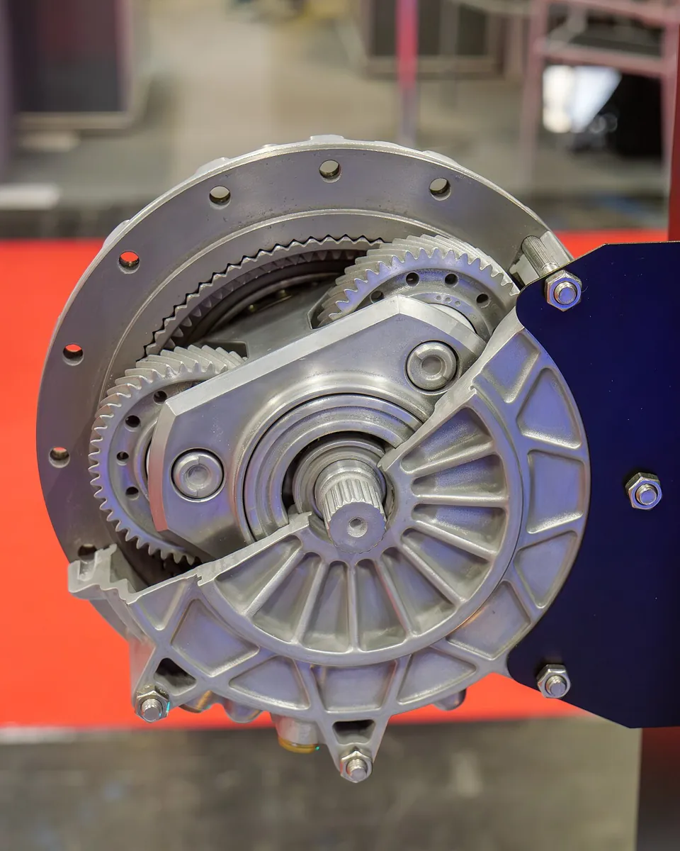
| Spur / planetary gearbox | Reduces speed, multiplies torque | Compact, efficient, common in gearmotors | Backlash (play) between teeth |
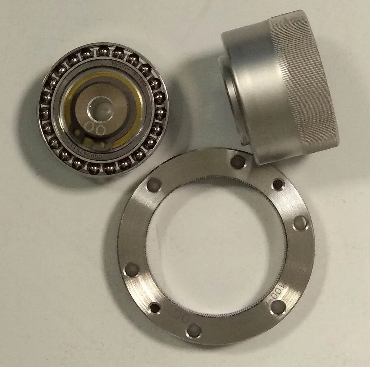
| Harmonic (strain-wave) drive | Very high reduction in one stage | Zero backlash, compact, accurate | Costly; flexspline has a fatigue life |
| Worm gear | High reduction at 90° | Often hard to back-drive — holds the load when unpowered | Low efficiency; heat |
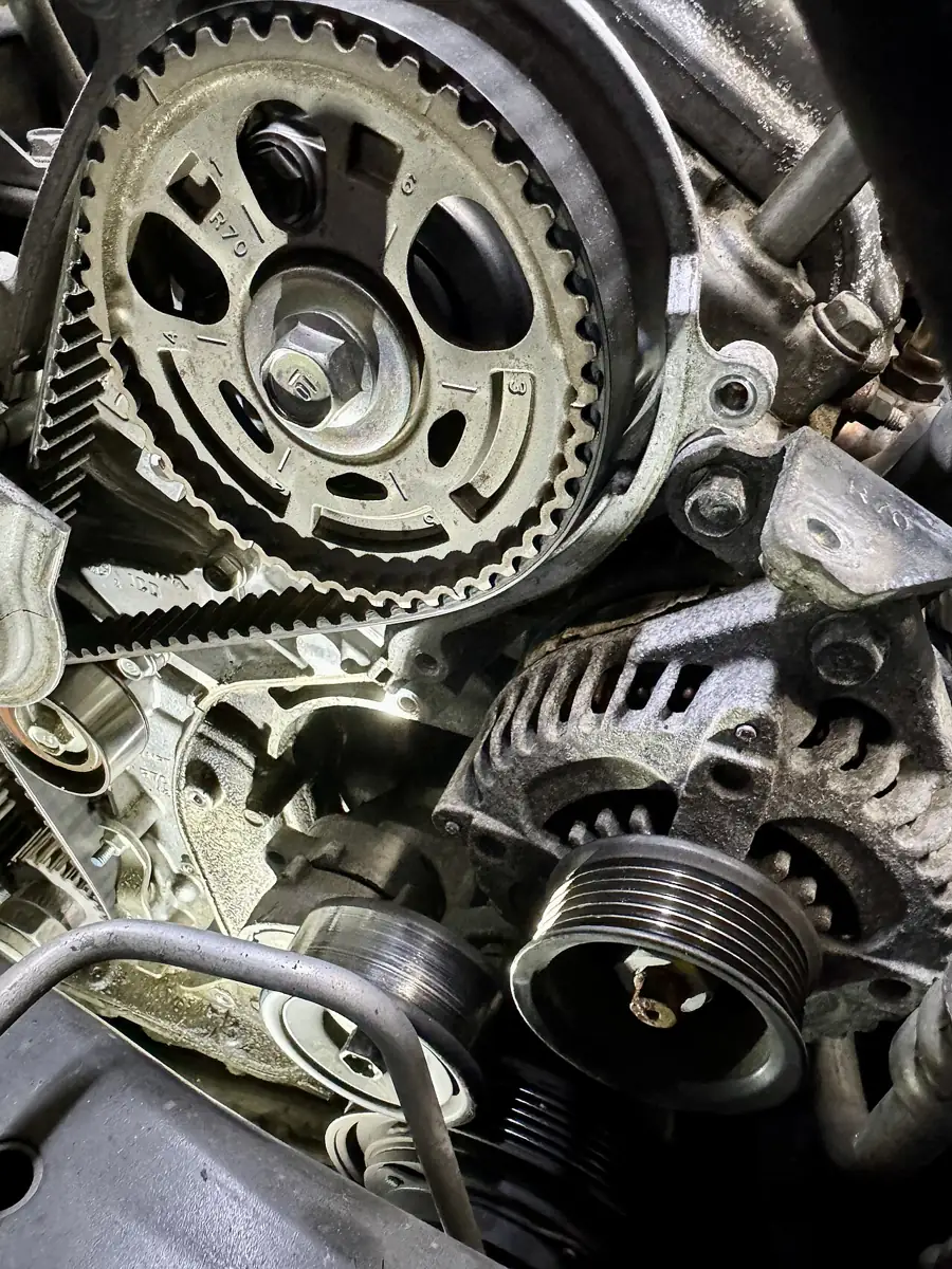
| Timing belt + pulleys | Moves torque to another place; ratio = teeth ratio | Light, quiet, lets you put the motor at the base | Stretch; needs tensioning |
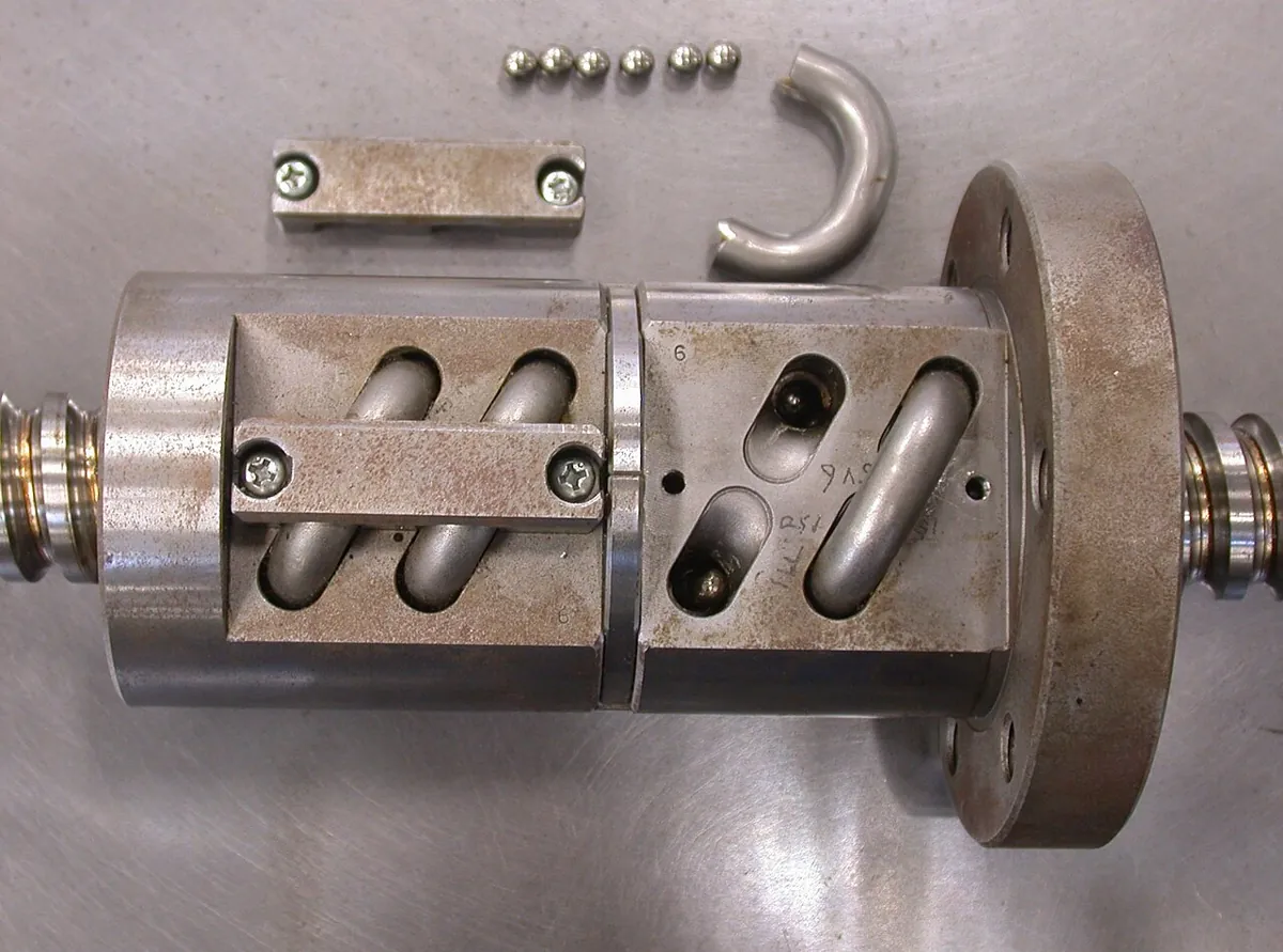
| Lead / ball screw | Turns rotation into straight-line motion | Large force, precise linear moves | Speed limited by lead; ball screws cost more |
| Cable / tendon | Pulls a joint from a distance | Very light joints (robot hands) | Stretch, friction, routing |
Modern Robotics defines backlash as the amount of rotation available at the output without motion at the input — the “play” you feel when you wiggle a cheap servo horn. In a long arm, a little backlash at the shoulder becomes a big wobble at the tip (Lesson 9).
Visual
Visualise it: trade speed for torque
Pick a motor and a transmission and watch what happens to the **output speed and torque**. Notice the trade: whatever you gain in torque, you lose in speed — and every stage loses a little to friction.
Interactive · Actuator & transmission lab

Integrated motor + gearbox + position loop. Great for early arms; torque limited.
Output speed
~0.7 rpm
Torque gain (ideal)
×150
Teaching model only — real gearboxes have losses, backlash, and current limits. Stage 4 drivers still apply: never GPIO-direct a motor.
Code lab
Code lab: holding torque, gear ratios and a real servo
The script does four things: (1) adds up the shoulder holding torque for an example arm; (2) shows how one fast, weak example motor changes through gear ratios 1, 10, 100 and 258.5 (with assumed efficiencies); (3) compares our need with the ROBOTIS XL430-W250’s published stall torque and speed; (4) works out a belt ratio and a lead screw. Run it with python3 gear_torque.py.
"""gear_torque.py - how much torque does a joint need, and what does a gearbox do?
Physics: torque = force x lever arm (OpenStax University Physics 10.6).
Gearing: an ideal gearhead with ratio G multiplies torque by G and divides speed by G
(Modern Robotics 8.9); a real one also loses some to friction (efficiency eta)."""
import math

G_EARTH = 9.81

def holding_torque(mass_kg, dist_m):
    """Worst case: arm held horizontal, so the full weight acts at right angles."""
    return mass_kg * G_EARTH * dist_m

# --- 1. Torque needed at a shoulder (example arm, replace with your numbers) ---
upper_arm = (0.080, 0.06)   # mass kg, distance of its centre from the shoulder (m)
forearm = (0.060, 0.17)
elbow_servo = (0.055, 0.12)
payload = (0.050, 0.22)
parts = {"upper arm": upper_arm, "forearm": forearm, "elbow servo": elbow_servo, "payload": payload}
total = 0.0
print("== 1. Shoulder holding torque (arm horizontal) ==")
for name, (m, d) in parts.items():
    t = holding_torque(m, d)
    total += t
    print(f"{name:12s} {m*1000:5.0f} g at {d*100:4.1f} cm -> {t:.3f} N.m")
print(f"total {total:.3f} N.m = {total/0.0981:.1f} kg.cm ; with 2x safety factor {2*total:.3f} N.m")

# --- 2. What a gearbox does to a fast, weak motor (example motor) ---
motor_speed_rpm, motor_stall_nm = 10000, 0.010
print("\n== 2. Same motor, different gear ratios (eta = efficiency) ==")
print(" G      eta   output stall torque   output no-load speed")
# eta values are assumed examples for illustration, not datasheet numbers
for g, eta in [(1, 1.00), (10, 0.90), (100, 0.75), (258.5, 0.70)]:
    print(f"{g:6.1f}  {eta:.2f}   {motor_stall_nm*g*eta:8.3f} N.m          {motor_speed_rpm/g:8.1f} rpm")

# --- 3. A real smart servo: ROBOTIS XL430-W250 e-manual numbers ---
print("\n== 3. XL430-W250 (from its e-manual) ==")
stall, rpm = 1.4, 57   # N.m and rev/min at 11.1 V; gear ratio 258.5:1
print(f"stall torque {stall} N.m at 11.1 V, no-load {rpm} rpm -> {rpm*6:.0f} deg/s unloaded")
print(f"holding our shoulder needs {total:.3f} N.m = {100*total/stall:.0f}% of its stall torque")

# --- 4. Belts and lead screws ---
print("\n== 4. Other transmissions ==")
t20, t60 = 20, 60
print(f"belt 20T -> 60T pulley: ratio {t60/t20:.1f}:1 (3x torque, 1/3 speed)")
lead_mm, screw_rpm, screw_torque, eta = 8.0, 300, 0.2, 0.9   # eta assumed for illustration
# energy balance: one turn puts in 2*pi*T of work and pushes the nut one lead: F * lead = 2*pi*eta*T
speed = lead_mm * screw_rpm / 60
force = 2 * math.pi * eta * screw_torque / (lead_mm / 1000)
print(f"lead screw, 8 mm lead at 300 rpm -> {speed:.0f} mm/s; 0.2 N.m in -> about {force:.0f} N push")
Output (run with python3 gear_torque.py)
== 1. Shoulder holding torque (arm horizontal) ==
upper arm       80 g at  6.0 cm -> 0.047 N.m
forearm         60 g at 17.0 cm -> 0.100 N.m
elbow servo     55 g at 12.0 cm -> 0.065 N.m
payload         50 g at 22.0 cm -> 0.108 N.m
total 0.320 N.m = 3.3 kg.cm ; with 2x safety factor 0.640 N.m

== 2. Same motor, different gear ratios (eta = efficiency) ==
 G      eta   output stall torque   output no-load speed
   1.0  1.00      0.010 N.m           10000.0 rpm
  10.0  0.90      0.090 N.m            1000.0 rpm
 100.0  0.75      0.750 N.m             100.0 rpm
 258.5  0.70      1.809 N.m              38.7 rpm

== 3. XL430-W250 (from its e-manual) ==
stall torque 1.4 N.m at 11.1 V, no-load 57 rpm -> 342 deg/s unloaded
holding our shoulder needs 0.320 N.m = 23% of its stall torque

== 4. Other transmissions ==
belt 20T -> 60T pulley: ratio 3.0:1 (3x torque, 1/3 speed)
lead screw, 8 mm lead at 300 rpm -> 40 mm/s; 0.2 N.m in -> about 141 N push
Try it: change the arm length and payload and watch the required servo torque. Find the point where a small servo is no longer enough.
Interactive · Servo torque calculator
Torque needed
1.20 kg·cm
Same in SI
0.118 N·m
Servo rating
2.0 kg·cm
Load vs rating
60 %
Worst case is when the arm is horizontal (gravity pulls at 90°). Rule of thumb used by many hobbyists: keep the steady load at or below about half the rated (stall) torque. Rated torque comes from your servo's datasheet.
Real world
Transmissions inside real robots
- Industrial and collaborative arms: Modern Robotics describes arms with motors combined with 100:1 zero-backlash harmonic drive gearing in the joints.
- 3D printers and CNC machines: steppers with belts (fast axes) and lead screws (vertical axes).
- Hobby arms: RC servos — a DC motor, a gear train, a driver and a potentiometer in one box.
- Mobile robots: gearmotors or smart servos on the wheels; the TurtleBot3 Burger uses two XL430-W250s.
- Robot hands: tendons (cables) let small, light fingers be driven by motors in the forearm.

Bench build
Bench build: a safe servo holding test
Measure, don’t guess. You will hang a known small mass at increasing distances from a servo’s axis and watch for sag, buzzing and current — comparing reality with τ = m g d.
Mount
Clamp the servo firmly to the table edge with its shaft horizontal. Screw a straight servo arm (or a stiff ruler) to the horn.
Power safely
Servo red and brown/black to a 5–6 V supply; supply GND to Arduino GND; signal to pin 9. Put a multimeter in series with the supply (current range) if you have one.
Hold horizontal
Upload
slow_servo_steps.ino(from Lesson 2) and type the angle that makes the arm horizontal.Add load
Hang a small known mass (for example a 20 g bag of coins — weigh it) at 2 cm, then 4 cm, then 6 cm from the axis. Each time, note sag (degrees), sound and current.
Compute
For each position compute τ = m × 9.81 × d. Compare with your servo’s datasheet torque. At what torque did it start to sag or buzz?
Stop early
As soon as the servo buzzes continuously or gets warm, remove the load. You have found its practical limit — no need to cook it.
// slow_servo_steps.ino - move one joint in gentle 1-degree steps between soft limits.
// Servo signal on pin 9. Servo power comes from a SEPARATE 5-6 V supply, grounds joined.
#include <Servo.h>

Servo joint;
const int PIN = 9;
const int SOFT_MIN = 20;      // stay away from the hard end stops
const int SOFT_MAX = 160;
const int STEP_DELAY_MS = 15; // about 66 degrees per second

int angle = 90;

void moveTo(int target) {
  target = constrain(target, SOFT_MIN, SOFT_MAX);
  while (angle != target) {
    angle += (target > angle) ? 1 : -1;
    joint.write(angle);
    delay(STEP_DELAY_MS);
  }
  Serial.print("at ");
  Serial.println(angle);
}

void setup() {
  Serial.begin(9600);
  joint.write(angle);   // set the start position before attach() so it does not jump
  joint.attach(PIN);
  Serial.println("type an angle (20-160) and press Enter");
}

void loop() {
  if (Serial.available()) {
    int target = Serial.parseInt();
    if (target > 0) moveTo(target);
  }
}Debugging
Debugging actuators and transmissions
| Symptom | Likely cause | Fix |
|---|---|---|
| Arm sags under load, servo buzzes | Torque needed is near or above what the servo can give | Shorten links, move mass closer to the joint, use a stronger servo or add a counterweight/spring |
| Servo gets hot while just holding | Holding near its limit for a long time | Reduce load; rest the arm when idle; check the continuous rating, not stall |
| Tip wobbles when the arm stops | Backlash in gears, or a loose horn screw | Tighten the horn; preload with gravity; choose lower-backlash gearing |
| Belt-driven joint slips or jumps | Belt too loose or teeth skipping | Tension the belt; check pulley alignment |
| Lead-screw axis stalls at speed | Lead or speed too high for the motor torque | Lower speed; use a smaller lead for more force |
| Board resets when the joint starts | Supply sags under start-up current (Lesson 2) | Bigger supply, capacitor on the rail, separate logic supply |
Think
Think about it
Think
Meera has two choices for her arm’s shoulder: a servo rated 1.0 N·m stall at 6 V, or a smaller one rated 0.25 N·m. Her calculation says the shoulder needs 0.32 N·m holding torque. Arjun says, “0.32 is more than 0.25, but the big one is overkill — just use the small one and shorten the arm a little.” What would you advise, and why?
Experiment
Try it in the lab: size a shoulder joint
Thirty minutes with the transmission lab, the torque script and — optionally — the servo holding test.
Experiment
Size a shoulder joint
You will need
- Actuator & transmission lab (below, runs in your browser)
- Kitchen scale and ruler
- Notebook
- Optional: `gear_torque.py`; servo, 5–6 V supply, Arduino, multimeter
Steps
- In the transmission lab, pick one motor and try three gear ratios. Write the output torque and speed for each.
- Weigh the parts of your arm (or use the script’s example). Measure each part’s distance from the shoulder axis.
- Edit part 1 of `gear_torque.py` with your numbers and run it. Write your holding torque and the 2× value.
- Find a servo datasheet (or use the XL430-W250 numbers). Is it enough? What percentage of stall torque would you use?
- Optional bench: run the holding test and compare the load where your servo started to sag with the calculation.
Interactive · Actuator & transmission lab
Integrated motor + gearbox + position loop. Great for early arms; torque limited.
Output speed
~0.7 rpm
Torque gain (ideal)
×150
Teaching model only — real gearboxes have losses, backlash, and current limits. Stage 4 drivers still apply: never GPIO-direct a motor.
Torque is force times distance, so length is the enemy of a shoulder. Gears trade speed for torque, but cost efficiency, backlash and reflected inertia. Stall torque is a limit, not a working point.
Knowledge check
Check your understanding
Knowledge check
1. An ideal gearbox with ratio G = 2 does what to a motor’s maximum torque and speed?
2. A 50 g payload held horizontally 22 cm from the shoulder needs about how much torque?
3. Why do robot joints often use gear ratios of 100 or more?
4. Which transmission has zero backlash and very high reduction in a compact package?
5. Backlash is…
6. Inside a typical RC servo you find…
7. Why should you not size a joint right at the motor’s stall torque?
8. A 20-tooth pulley drives a 60-tooth pulley. The output…
9. Which actuator moves in discrete steps with repeatable positioning?
10. The motor’s rotor inertia, seen at the joint through a gear ratio G, appears…
Mini assignment
Hands-on assignment
Mini assignment
Size every joint of a 3-joint desk arm
Design the actuators for a shoulder–elbow–wrist desk arm: compute holding torques, choose transmissions and servos, and test one joint on the bench if you can.
Deliverables
- A table with each joint: masses beyond it, distances, holding torque, 2× value, chosen actuator and its datasheet torque (with voltage).
- Your edited `gear_torque.py` output for your own arm.
- A one-paragraph choice of transmission for each joint (direct servo, belt, gearbox…) with one reason each.
- If you have hardware: your holding-test table (mass, distance, computed torque, sag, current) and a one-line conclusion.
Do this, step by step
- Sketch a shoulder–elbow–wrist desk arm and write the mass of each link, servo and the payload, and their distances from each joint.
- Compute holding torque at each joint (τ = m × g × d, summed for everything beyond the joint), then double it for a safety margin.
- Put your numbers into
gear_torque.py, run it and check the script agrees with your hand result. - Pick an actuator and transmission for each joint and note the datasheet torque and the voltage it is rated at.
- If you have hardware: do the holding test on one joint (servo on its own supply, common ground) and record mass, distance, torque, sag and current.
Stuck? Hints, one at a time
- Hint 1: Start at the wrist. It only carries the gripper and payload. Then the elbow carries the wrist too, and the shoulder carries everything.
- Hint 2: Each part’s distance is measured from the joint you are sizing, not from the base.
- Hint 3: A servo’s own mass counts as a load for every joint behind it.
- Hint 4: If the shoulder needs too much, try moving the elbow servo to the base and driving the elbow with a belt or a linkage.
Challenges (pick by level)
- 🟢 Easy: Convert 3.3 kg·cm to N·m. *Hint:* × 0.0981.
- 🟢 Easy: From the XL430-W250 e-manual numbers, convert 57 rpm into degrees per second.
- 🟡 Medium: How far from the shoulder can a 100 g payload be if the servo may use only 0.5 N·m in total and the arm itself already needs 0.2 N·m?
- 🟡 Medium: A lead screw has a 2 mm lead. At 300 rpm how fast does the nut move? With 0.2 N·m and 90% efficiency, what force does it push?
- 🟠 Hard-ish: Add a counterweight behind the shoulder in the script. Find the mass and distance that cut the holding torque in half.
- 🔴 Hard: Explain, with numbers, why a 258.5:1 servo is hard to back-drive by hand. *Hint:* reflected inertia G² and gear friction.
- ⚫ Expert: Read Modern Robotics Section 8.9 and write a one-page note on how the motor’s speed–torque curve changes with gear ratio, using your own arm as the example.
Next step
Your joints can move and hold. In Lesson 6 — Sensors & Proprioception you give the robot a sense of its own body: potentiometers, encoders, IMUs — and the difference between knowing yourself and knowing the world.
Look back: Lesson 4: Configuration Space Intuition. Next: Lesson 6: Sensors & Proprioception. Related: Stage 4 — Electronics and Stage 7 — Control Systems & PID.
Sources
- Modern Robotics — K. M. Lynch & F. C. Park (preprint PDF) — Ch. 2 intro: motors are fast and weak, so transmissions (gears, cables, belts, chains) reduce speed and amplify torque; definition of backlash; Sec. 8.9: τ_gear = ηGτ_motor, G = 2 doubles torque and halves speed, DC motors of 10 000 rpm or more, joint ratios of 100 or more, apparent inertia G²·I_rotor; harmonic drive gearing in arm joints.
- OpenStax University Physics Volume 1, 10.6 Torque — torque depends on force, lever arm and angle; the door example.
- Adafruit Motor Selection Guide — brushed and brushless DC motors, steppers (discrete steps, repeatable positioning), gearmotors, RC servos (DC motor, gear train, H-bridge and potentiometer feedback).
- Harmonic Drive LLC: Strain wave gear technology — Wave Generator, Flexspline and Circular Spline; two fewer teeth; one tooth per 180° of the Wave Generator; zero backlash.
- ROBOTIS e-Manual: XL430-W250 — 258.5:1 gear ratio; stall torque 1.0 / 1.4 / 1.5 N·m at 9 / 11.1 / 12 V; no-load 57 rpm at 11.1 V; note that stall torque differs from continuous output.
- SparkFun Learn: Hobby Servo Tutorial — servo current rises with mechanical load, up to an ampere or more.
- Photos: Wikimedia Commons (credits under each image).
Self-attested for now — keep artifacts in your lab notebook.
Complete
Today's goal
0 of 1 done today
Mark this lesson complete when you have worked the experiment, knowledge check, and assignment (even roughly).