
Robotics Fundamentals · Lesson 02
Robot Systems Recap
Est. 45–60 min
Why
Why you must see the whole chain, not just one part
In Stage 4 you learnt each part on its own: voltage and current, MOSFET switches, GPIO, the ADC, PWM, microcontrollers, serial buses and embedded architecture. This chapter stitches them into one system and gives you a habit you will use for the rest of your robotics life: follow a command through every layer, and when something fails, break the chain one link at a time until you find the weak link.
By the end you will be able to: draw the seven-link chain (power → ground → sense → decide → command → drive → body) for any small robot; separate the power path from the signal path; explain why many robots split work between a microcontroller and a bigger computer; predict the symptom when each link breaks; and run a safe system check on a real servo bench.
Concept
A robot system in plain words: power, signals and motion flowing through a chain
Think of a water-delivery chain in a village. The well is the power source. The pipes are the wires. The village head who decides which house gets water is the controller. The tap at each house is the driver. If the pipe from the well is thin, no amount of good decisions will fill the tanks. If the village head’s messenger is late, water arrives at the wrong time. A robot is the same: power flows one way, information flows in a loop, and both must be healthy.
The seven-link chain
| # | Link | Small-arm example | What must be true | Stage 4 lesson |
|---|---|---|---|---|
| 1 | Power | 5–6 V servo supply + USB for the board | Supply does not sag when servos start | Voltage, current; capacitors |
| 2 | Ground | Common GND between board and servo supply | Both share the same 0 V reference | DC circuits |
| 3 | Sense | Potentiometer or encoder on the joint | Reading changes when the joint moves | Analog signals & ADC |
| 4 | Decide | loop() reads, compares, decides | Loop runs fast and steadily | Microcontrollers; Arduino |
| 5 | Command | PWM pulse on a signal pin | 1–2 ms pulses about every 20 ms | PWM, motor & servo control |
| 6 | Drive | Servo’s own driver chip, or a PCA9685 board | Current comes from the supply, not the pin | Diodes & MOSFETs; sensors & actuators |
| 7 | Body | Horn, link, bearing | Joint turns freely, no binding | Stage 5, Lessons 3 and 5 |
The command numbers come from SparkFun’s hobby servo tutorial: a servo expects a pulse every 20 ms (50 Hz), and the pulse width — about 1 ms to 2 ms, centred at 1.5 ms — sets the position. Inside the servo, a potentiometer measures the output shaft and the servo’s own electronics drive the motor until the position matches. That is already a closed loop (Lesson 8).
Two paths: power and signal
- Power path (thick wires): supply → servo/motor driver → motor → back to ground. Carries amperes.
- Signal path (thin wires): sensor → microcontroller → signal pin → driver input. Carries information at milliamps.
- They meet only at the ground. The common ground gives every signal the same 0 V reference. Without it, a 5 V pulse means nothing to the servo.
Pin current (signal) ≪ motor current (power)
- SparkFun notes a small idle servo may draw about 10 mA, but a large servo turning a heavy lever can draw an ampere or more — far beyond what a microcontroller pin can supply.
The brain split: microcontroller + computer
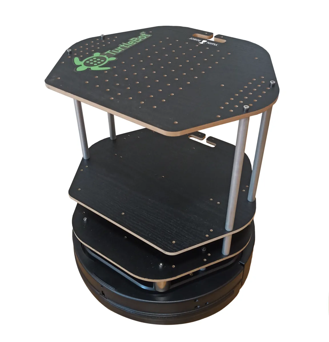
Bigger robots often have two brains. The TurtleBot3 Burger is a good example from its official spec sheet: a Raspberry Pi 4 single-board computer runs the high-level software, while an OpenCR board with a 32-bit Arm Cortex-M7 microcontroller handles the motors and sensors. The motors are two DYNAMIXEL XL430-W250 smart servos, the main exteroceptive sensor is a 360° laser distance sensor (LDS-02), and a 3-axis gyroscope and 3-axis accelerometer form its IMU. The fast, timing-critical jobs live close to the hardware; the heavy thinking lives on the computer.
| Job | Microcontroller | Computer (SBC / PC) |
|---|---|---|
| Servo/motor pulses, encoder counting | ✅ steady timing | ❌ timing can wobble |
| Limit switches, e-stop sense | ✅ instant reaction | ⚠️ only as a second layer |
| Maps, cameras, planning | ❌ too little memory | ✅ plenty of CPU and memory |
| Talking between them | UART / USB serial | UART / USB serial |
Visual
Visualise it: wire a small robot system
Wire a small robot system the safe way. Watch which wires carry **power** and which carry **signals** — and notice that the only connection between the two worlds is the **common ground**.
Interactive · Robot Electronics Wiring Lab
Assemble a full educational architecture: power, common ground, MCU, driver, actuators, sensors, and clean signal paths. Unlock Embedded Robot Ready.
- Missing: Dedicated low-voltage PSU for actuators
- Missing: Common ground MCU ↔ driver ↔ sensors
- Missing: MCU / embedded brain present
- Missing: Motor/servo driver between MCU and actuator
- …+3 more
Low-voltage educational sim · sims ≠ datasheets · never access real hardware from the browser.
Code lab
Code lab: trace the chain and predict each failure
This script stores the seven links and what must be true for each. Then it “breaks” each link in turn and prints the symptom you would see and which later links now get bad input. Run it with python3 system_trace.py.
"""system_trace.py - follow one command through a robot's layers, then break one link at a time."""

CHAIN = [  # (layer, part, what must be true for the next layer to work)
    ("Power", "5-6 V servo supply + USB for the board", "servo rail does not sag when servos start"),
    ("Ground", "common GND between board and servo supply", "signals have the same 0 V reference"),
    ("Sense", "potentiometer on the joint (analog pin)", "reading changes when the joint moves"),
    ("Decide", "loop() reads, compares, decides", "loop runs every 20 ms or faster"),
    ("Command", "PWM pulse on a signal pin", "pulse 1000-2000 us at 50 Hz"),
    ("Drive", "servo's own driver chip (or a PCA9685)", "current comes from the supply, not the pin"),
    ("Body", "horn, link, joint bearing", "joint turns freely, no binding"),
]

FAULTS = {
    "Power": "board resets or servo twitches when it starts moving (brownout)",
    "Ground": "servo jitters or ignores commands; readings look noisy",
    "Sense": "loop believes the joint never moved, keeps pushing to the end stop",
    "Decide": "robot reacts late; moves overshoot",
    "Command": "servo does not move or jumps to one end",
    "Drive": "pin or regulator overheats; board may be damaged",
    "Body": "motor stalls, gets hot, current spikes",
}

print("== Healthy chain ==")
for i, (layer, part, ok) in enumerate(CHAIN, 1):
    print(f"{i}. {layer:8s} {part:44s} check: {ok}")

print("\n== Break one link at a time ==")
for layer, *_ in CHAIN:
    downstream = [l for l, *_ in CHAIN][[l for l, *_ in CHAIN].index(layer) + 1:]
    print(f"{layer:8s} broken -> {FAULTS[layer]}")
    print(f"{'':8s}           layers that now get bad input: {', '.join(downstream) or 'none (last link)'}")
Output (run with python3 system_trace.py)
== Healthy chain ==
1. Power    5-6 V servo supply + USB for the board       check: servo rail does not sag when servos start
2. Ground   common GND between board and servo supply    check: signals have the same 0 V reference
3. Sense    potentiometer on the joint (analog pin)      check: reading changes when the joint moves
4. Decide   loop() reads, compares, decides              check: loop runs every 20 ms or faster
5. Command  PWM pulse on a signal pin                    check: pulse 1000-2000 us at 50 Hz
6. Drive    servo's own driver chip (or a PCA9685)       check: current comes from the supply, not the pin
7. Body     horn, link, joint bearing                    check: joint turns freely, no binding

== Break one link at a time ==
Power    broken -> board resets or servo twitches when it starts moving (brownout)
                   layers that now get bad input: Ground, Sense, Decide, Command, Drive, Body
Ground   broken -> servo jitters or ignores commands; readings look noisy
                   layers that now get bad input: Sense, Decide, Command, Drive, Body
Sense    broken -> loop believes the joint never moved, keeps pushing to the end stop
                   layers that now get bad input: Decide, Command, Drive, Body
Decide   broken -> robot reacts late; moves overshoot
                   layers that now get bad input: Command, Drive, Body
Command  broken -> servo does not move or jumps to one end
                   layers that now get bad input: Drive, Body
Drive    broken -> pin or regulator overheats; board may be damaged
                   layers that now get bad input: Body
Body     broken -> motor stalls, gets hot, current spikes
layers that now get bad input: none (last link)How it works: the list CHAIN keeps the order, which matters — a fault upstream poisons everything downstream. The slice [index + 1:] picks every link after the broken one.
Real world
Robot systems you can open up and trace
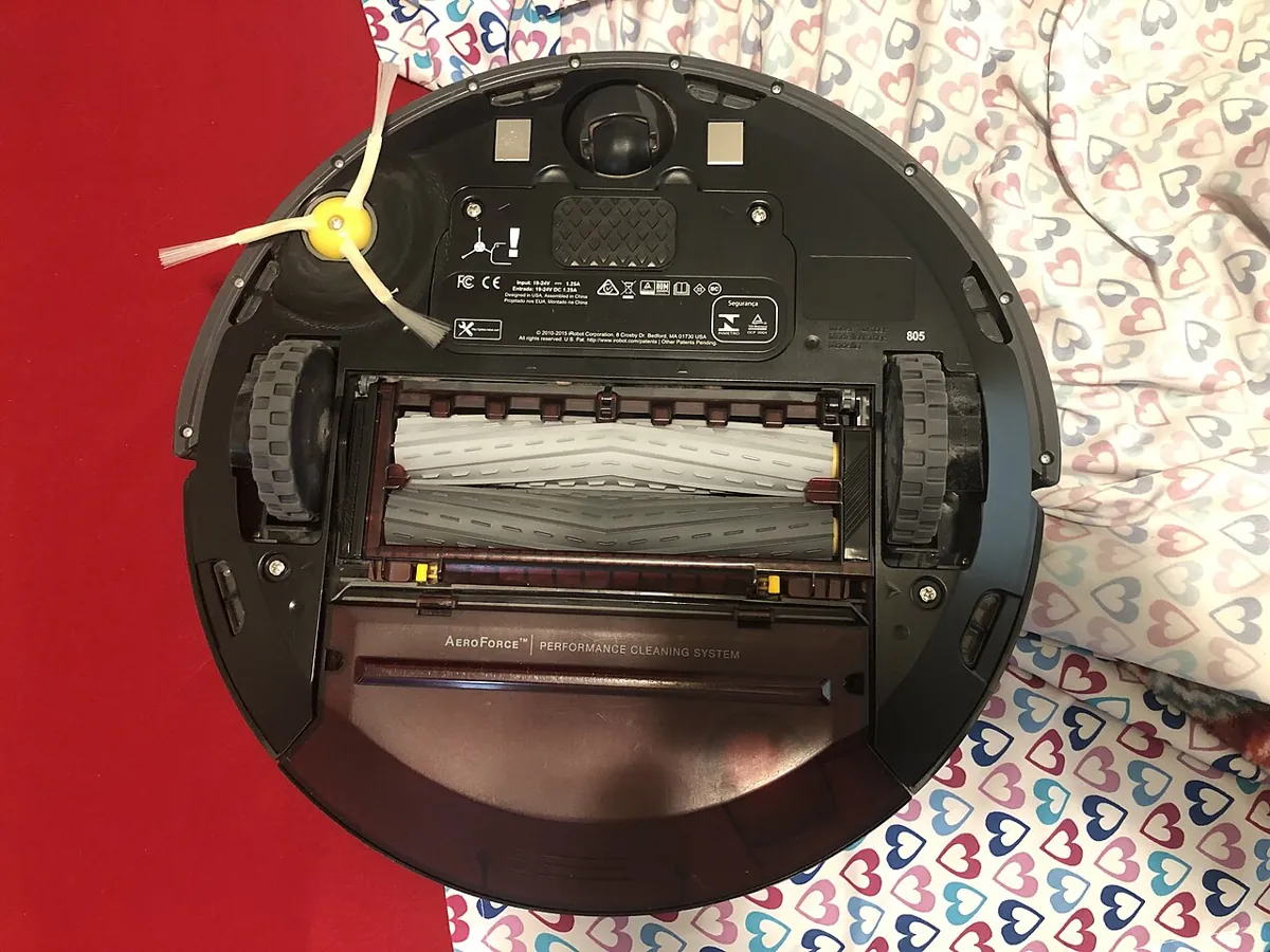
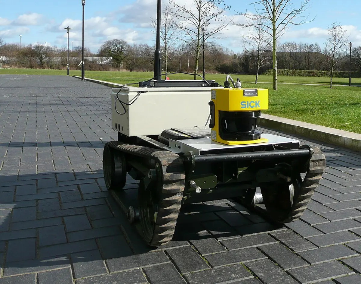
- Robot vacuums: wheel motors, brush motors, bump and cliff sensors, a battery and one controller — a full chain in a disc.
- Teaching robots: the TurtleBot3 splits work between a Raspberry Pi 4 and an OpenCR motor-control board, connected by serial.
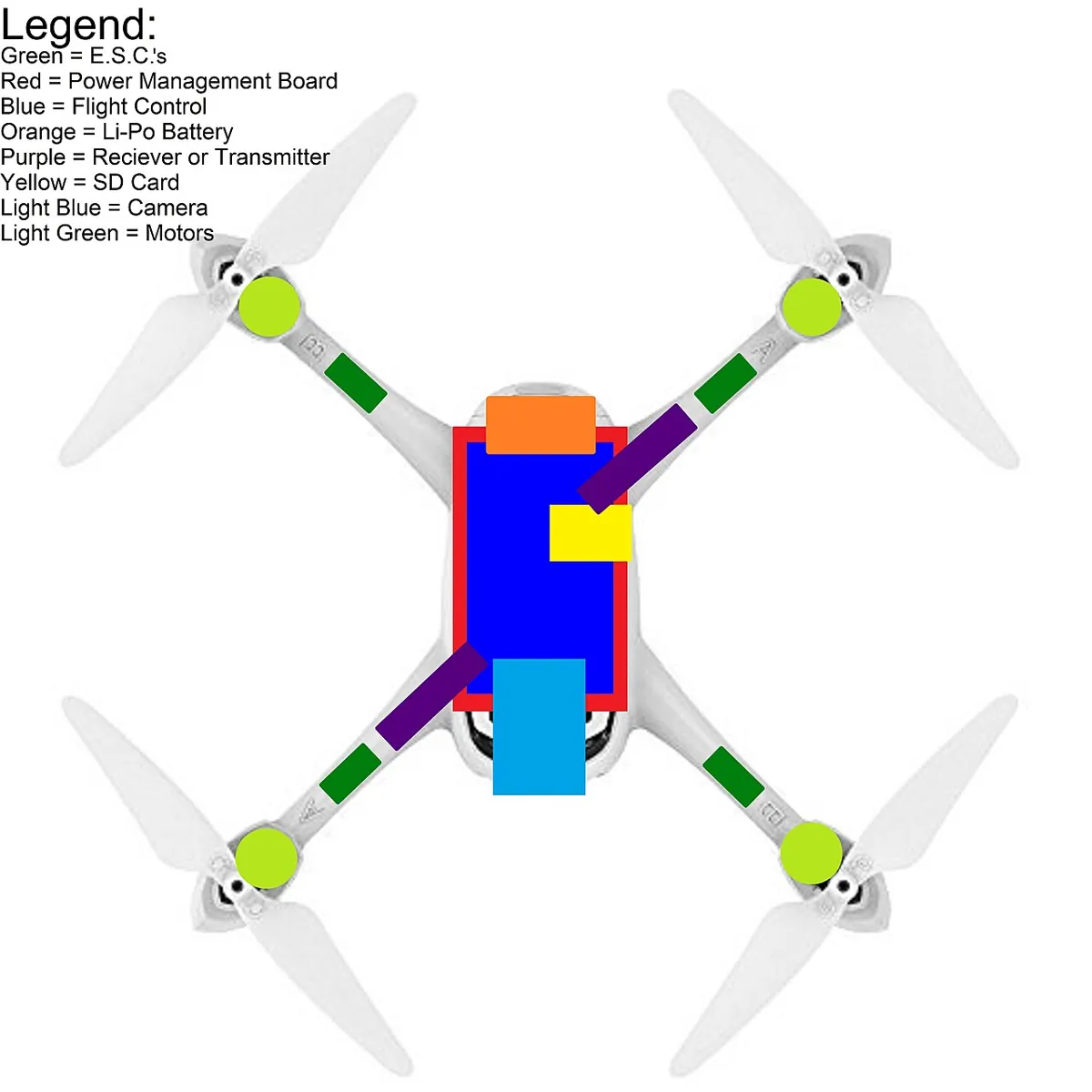
- Drones: a flight controller reads motion sensors and drives four motor controllers from one battery; a sagging battery causes the same brownout problems as your servo bench.
- Industrial arms: OSHA describes the controller loop: sensors feed the computer, and the computer sends output commands to the manipulator and end-effector.
Bench build
Bench build: a full system check on one servo joint
Rebuild your Stage 4 servo bench and check every link deliberately, in order. The sketch moves one servo in gentle 1° steps between soft limits (20°–160°) so nothing slams into an end stop.
Power
Set a bench supply (or a 4×AA pack) to 5–6 V for the servo. Measure it with a multimeter before connecting anything.
Ground
Connect supply GND to the Arduino GND. This is the one wire that joins the power and signal worlds.
Command
Servo signal (usually orange or white) to pin 9. Servo red to the supply +, servo brown/black to supply GND. Nothing from the servo goes to the Arduino 5 V pin.
Decide
Upload
slow_servo_steps.ino, open the Serial Monitor at 9600 baud and type 90, then 45, then 135.Measure
Watch the supply voltage while the servo moves. SparkFun’s advice: measure the current and check whether the supply sags while servos turn.
Body
With the power off, turn the horn by hand gently. Does it bind? Is the horn screw tight?
// slow_servo_steps.ino - move one joint in gentle 1-degree steps between soft limits.
// Servo signal on pin 9. Servo power comes from a SEPARATE 5-6 V supply, grounds joined.
#include <Servo.h>

Servo joint;
const int PIN = 9;
const int SOFT_MIN = 20;      // stay away from the hard end stops
const int SOFT_MAX = 160;
const int STEP_DELAY_MS = 15; // about 66 degrees per second

int angle = 90;

void moveTo(int target) {
  target = constrain(target, SOFT_MIN, SOFT_MAX);
  while (angle != target) {
    angle += (target > angle) ? 1 : -1;
    joint.write(angle);
    delay(STEP_DELAY_MS);
  }
  Serial.print("at ");
  Serial.println(angle);
}

void setup() {
  Serial.begin(9600);
  joint.write(angle);   // set the start position before attach() so it does not jump
  joint.attach(PIN);
  Serial.println("type an angle (20-160) and press Enter");
}

void loop() {
  if (Serial.available()) {
    int target = Serial.parseInt();
    if (target > 0) moveTo(target);
  }
}Debugging
Debugging: walk the chain
| Symptom | Likely broken link | Check / fix |
|---|---|---|
| Board resets when the servo starts moving | Power (brownout) | Separate servo supply; add a capacitor across the servo rail; check supply current rating |
| Servo jitters, ignores commands | Ground | Join supply GND and board GND |
| Arm keeps pushing into the end stop | Sense or calibration | Check the sensor reading changes; check soft limits |
| Moves are late or jerky | Decide | Remove long delay() calls; keep the loop short |
| Servo does not move at all | Command | Correct pin? attach() called? Signal wire seated? |
| Regulator or pin gets hot | Drive | Servo is powered from the board — move it to its own supply |
| Servo hums and gets warm, joint does not move | Body | Binding, overload or a mechanical stop; power off and check |
Think
Think about it
Think
Arjun’s arm works perfectly when one servo moves at a time, but when all three servos move together the Arduino restarts and the arm flops. His code has not changed. Using the seven-link chain, which link do you check first, and what measurement would prove it?
Experiment
Try it in the lab: trace a command and break the chain
Twenty to thirty minutes with the wiring lab, the Python script and — if you have one — your servo bench.
Experiment
Trace a command and break the chain
You will need
- Robot electronics wiring lab (below, runs in your browser)
- Notebook
- Optional: `system_trace.py`; Arduino, servo, 5–6 V supply, multimeter
Steps
- In the wiring lab, build a correct circuit. Colour the power path red and the signal path blue in your notebook sketch.
- Remove the ground link in the lab (or imagine it). Write what happens and why.
- Run `system_trace.py`. For each broken link, write one real symptom you have seen on your own bench, or one you expect.
- On the real bench (optional): run `slow_servo_steps.ino` and measure the servo supply voltage while it moves, then while you gently resist the horn with a finger. Write both numbers.
- Write the seven links on a sticky note and keep it near your bench.
Interactive · Robot Electronics Wiring Lab
Assemble a full educational architecture: power, common ground, MCU, driver, actuators, sensors, and clean signal paths. Unlock Embedded Robot Ready.
- Missing: Dedicated low-voltage PSU for actuators
- Missing: Common ground MCU ↔ driver ↔ sensors
- Missing: MCU / embedded brain present
- Missing: Motor/servo driver between MCU and actuator
- …+3 more
Low-voltage educational sim · sims ≠ datasheets · never access real hardware from the browser.
Power flows one way, information flows in a loop, and they meet at the ground. When a robot misbehaves, the weak link is usually upstream of where the symptom appears.
Knowledge check
Check your understanding
Knowledge check
1. Which link joins the power world and the signal world?
2. A hobby servo expects a position pulse about every…
3. Why must a servo not be powered from a GPIO pin?
4. The Arduino resets every time the servos start moving. The most likely broken link is…
5. In the TurtleBot3 Burger, which part runs the motors and sensors with steady timing?
6. Why do we debug from link 1 (Power) downwards?
7. A servo hums and gets warm but the joint does not move. Which link do you suspect?
8. Why does `slow_servo_steps.ino` call `write()` before `attach()`?
9. Which job belongs on the microcontroller rather than the laptop?
Mini assignment
Hands-on assignment
Mini assignment
System chain poster and a real system check
Draw the seven-link chain for a robot of your choice and run (or plan) a full system check on one servo joint.
Deliverables
- A chain poster for one robot (your arm, a robot vacuum or a drone) with all seven links, the power path in red and the signal path in blue.
- A fault table: for each link, one symptom and one check.
- If you have the hardware: supply voltage at rest, while moving, and while you gently resist the horn — with a one-line conclusion.
- Your edited `system_trace.py` with one new link you added, and its output.
Do this, step by step
- Pick one robot (your arm, a robot vacuum or a drone) and draw its seven-link chain from the power source to the moving joint.
- Colour the power path red and the signal path blue; mark where the grounds join.
- Under each link write one symptom you would see if that link failed, and one check (meter reading, LED, Serial print) that proves it.
- Edit
system_trace.py: add one new link (for example a fuse or a level shifter), run it and copy the output. - If you have the servo bench: flash
slow_servo_steps.ino, measure supply voltage at rest, while moving and while you gently resist the horn, and write a one-line conclusion.
Stuck? Hints, one at a time
- Hint 1: Draw the battery or supply on the left and the moving part on the right. Everything else goes in between.
- Hint 2: Thick arrows for current (power), thin arrows for information (signals).
- Hint 3: Where do the thick and thin arrows touch? Only at the ground. Draw it as a line along the bottom.
- Hint 4: For the fault table, use the debugging table in this chapter as a model, then add one fault from your own experience.
Challenges (pick by level)
- 🟢 Easy: Write the seven links from memory in order.
- 🟢 Easy: From the TurtleBot3 spec, name the SBC, the MCU, the actuator model and the laser sensor.
- 🟡 Medium: Add a
"Comms"link tosystem_trace.pyand give it a realistic symptom. *Hint:* wrong baud rate. - 🟡 Medium: Measure your servo’s supply voltage while moving and while lightly resisting it. Explain the difference using SparkFun’s note on current and load.
- 🟠 Hard-ish: Draw the chain for a two-brain robot (laptop + Arduino). Mark which links the laptop owns and which the Arduino owns.
- 🔴 Hard: Turn the script into an interactive troubleshooter: type a symptom, get the top two likely links with checks.
- ⚫ Expert: Design a power distribution plan for three servos: supply rating, wire gauge you will look up, one bulk capacitor, fuse position, and the single star point for ground. Justify each choice from a datasheet or tutorial.
Next step
You can trace a system. In Lesson 3 — Joints, Links & DOF you zoom into the body: what a joint really is, how to count degrees of freedom, and why your 6DOF arm needs six motors.
Look back: Lesson 1: Why Robotics Fundamentals. Next: Lesson 3: Joints, Links & DOF. Related: Stage 4 — Electronics and Stage 0 — Orientation.
Sources
- SparkFun Learn: Hobby Servo Tutorial — 20 ms (50 Hz) frame with 1–2 ms pulses centred at 1.5 ms; internal potentiometer feedback; current from about 10 mA idle to an ampere or more under load; a sagging supply can reset microcontrollers.
- ROBOTIS e-Manual: TurtleBot3 Features — Burger: Raspberry Pi 4 SBC, OpenCR with a 32-bit Arm Cortex-M7 MCU, XL430-W250 actuators, 360° LDS-02, 3-axis gyro and accelerometer.
- OSHA Technical Manual, Section IV Chapter 4 — the control system loop: sensors to computer to output commands for the manipulator and end-effector.
- Arduino Servo library API —
attach(),write()and default pulse limits. - Photos: Wikimedia Commons (credits under each image).
Self-attested for now — keep artifacts in your lab notebook.
Complete
Today's goal
0 of 1 done today
Mark this lesson complete when you have worked the experiment, knowledge check, and assignment (even roughly).