
Robotics Fundamentals · Lesson 10
Frames, Pose & Tool Center Point
Est. 55–70 min
Why
Why “10 cm to the left” means nothing until you name the frame
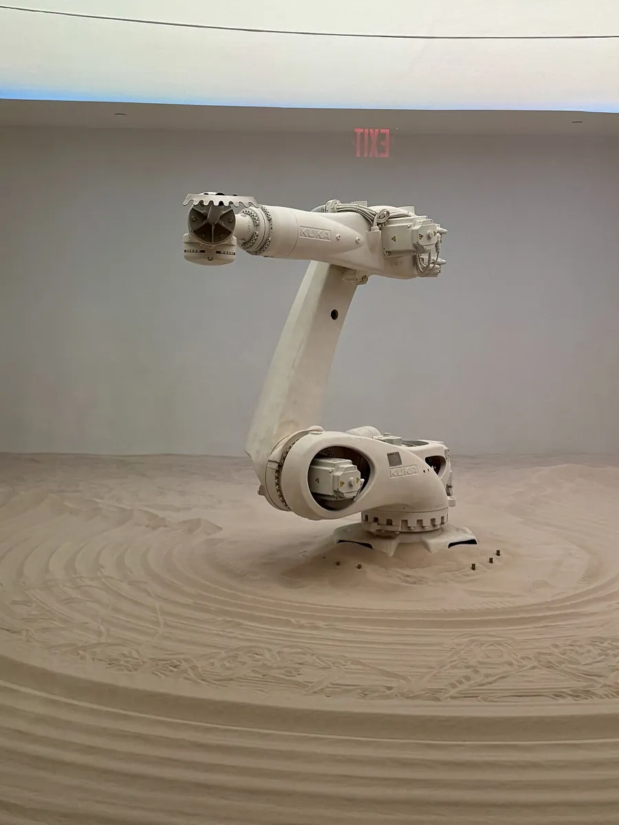
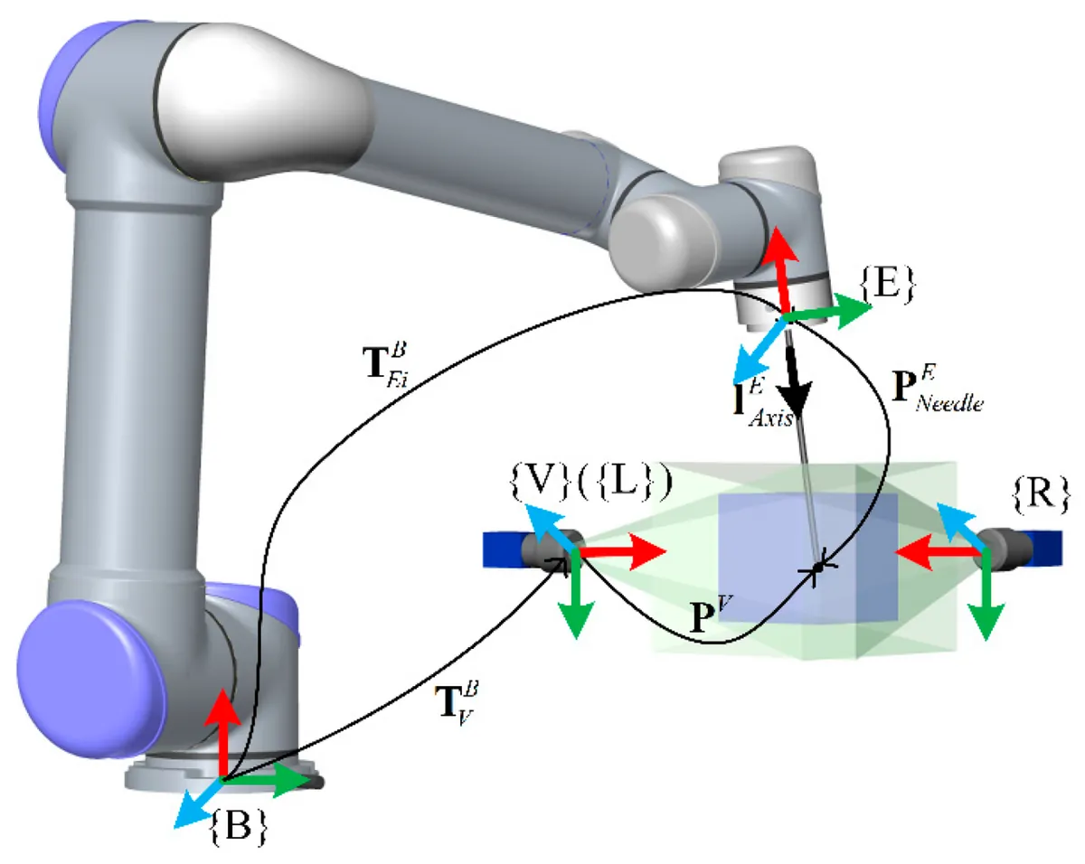
A frame is a coordinate system attached to something: the table, the robot base, the camera, the gripper. A pose is where something is *and* which way it points, measured in a frame. The tool center point (TCP) is, in OSHA’s words, the origin of the tool coordinate system — the exact point on the tool that all your motion commands are about. Get the frames right and a camera can tell an arm where to pick; get one sign wrong and the arm reaches for a mirror image.
By the end you will be able to: draw a right-handed frame and apply the right-hand rule; write a 2-D pose as (x, y, θ) and know what a 3-D pose needs; chain frames from base to elbow to flange to TCP; change the TCP when the tool changes; convert a point from a camera frame to the base frame and back; use the ROS conventions (REP 103: x forward, y left, z up, SI units; REP 105: base_link, odom, map); and measure a real TCP offset on the bench.
Concept
Frames, pose and the TCP in plain words
Think of giving directions in an Indian railway station. “Platform 3, coach S4, seat 23” works because everyone agrees where platform 1 is and which way coach numbers run. Change the station and the same words point somewhere else. A frame is that shared agreement: an origin (where zero is) and directions for x, y and z. Every number a robot uses — a joint position, a camera detection, a target — only makes sense *in some frame*.
Right-handed frames
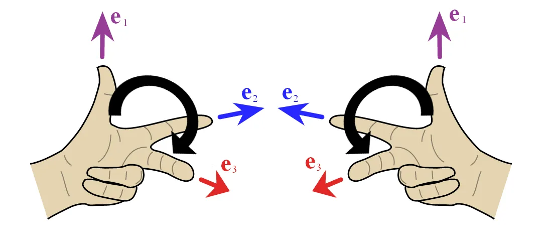
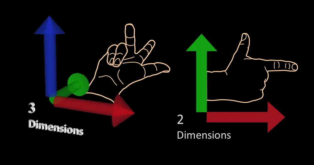
Modern Robotics uses right-handed frames throughout, and ROS’s REP 103 says all its systems are right-handed too. Point your right hand’s index finger along x and your middle finger along y; your thumb points along z. For rotations, curl your right fingers around an axis with your thumb along it: the fingers show the positive direction of rotation.
Pose: position + orientation
| World | Position | Orientation | Pose numbers |
|---|---|---|---|
| 2-D (a table top) | x, y | θ (one angle) | 3 numbers — like the coin in Lesson 3 |
| 3-D (a gripper in space) | x, y, z | Three angles, or a rotation matrix / quaternion | 6 independent numbers |
Notice these numbers match the rigid-body DOF from Lesson 3: 3 in the plane, 6 in space. A pose is just a configuration of one rigid body — the tool — written in a chosen frame.
Chaining frames: base → link → flange → TCP
Each joint and link adds one step. In 2-D, to express a pose *b* (given in frame A) in A’s parent frame, rotate it by A’s angle and add A’s position:
x = aₓ + bₓ cos θₐ − b_y sin θₐ, y = a_y + bₓ sin θₐ + b_y cos θₐ, θ = θₐ + θ_b
- This is the 2-D version of a homogeneous transform. Apply it once per link: base → elbow → flange → TCP. Stage 8 does the same with 4×4 matrices in 3-D.
The tool center point (TCP)
The flange is where the tool bolts on; the TCP is the working point of the tool — the gripper’s fingertip centre, the pen tip, the welding wire tip. Robot controllers let you set a tool offset from the flange to the TCP. When the tool changes, you change the offset, and the robot keeps drawing the same circle with the new tool. OSHA describes coordinated straight-line motion as the tool center point moving along a pre-specified linear path — which is only possible if the TCP is defined correctly.
ROS frame conventions you will meet
| Convention | What it says |
|---|---|
| Units (REP 103) | SI units: metres, kilograms, seconds, amperes; angles in radians |
| Body axes (REP 103) | x forward, y left, z up |
| Camera optical frame (REP 103) | z forward, x right, y down (a second frame with an _optical suffix) |
| base_link (REP 105) | Rigidly attached to the robot base |
| odom (REP 105) | World-fixed, continuous, but can drift over time — good short-term |
| map (REP 105) | World-fixed, should not drift, but can jump when localisation updates — good long-term |
Visual
Visualise it: move a frame and see its pose
Change the robot’s **position and heading** and watch its pose numbers (x, y, θ) update. Then imagine a second frame on the robot’s gripper — where would its origin be?
Interactive · Robot pose / transformation demo
Tip (x, y)
(152.1, 75.4)
Tip yaw
-5.0°
Simplification: planar 2R arm. Each joint adds a rotation; tip pose is the product of link transforms — the same idea as homogeneous chains on a 6DOF arm.
Code lab
Code lab: compose frames, move the TCP, use a camera
Two small functions do all the work: compose() expresses a pose given in a child frame in its parent frame, and invert() reverses a frame. The script chains base → elbow → flange, tries three tools, and converts a block seen by a camera into the arm’s base frame — then back again as a check. Run it with python3 frames_tcp.py.
"""frames_tcp.py - frames, pose and the tool centre point (TCP) in 2-D.
A pose in the plane is (x, y, theta). Chaining poses = composing frames: base -> flange -> TCP."""
import math

def compose(a, b):
    """pose b expressed in frame a  ->  pose in a's parent frame"""
    ax, ay, at = a; bx, by, bt = b
    c, s = math.cos(at), math.sin(at)
    return (ax + c * bx - s * by, ay + s * bx + c * by, at + bt)

def invert(a):
    ax, ay, at = a
    c, s = math.cos(at), math.sin(at)
    return (-c * ax - s * ay, s * ax - c * ay, -at)

def show(name, p):
    print(f"{name:28s} x={p[0]*100:7.2f} cm  y={p[1]*100:7.2f} cm  theta={math.degrees(p[2]):7.1f} deg")

L1, L2 = 0.12, 0.10
t1, t2 = math.radians(30), math.radians(45)
base_to_elbow = compose((0, 0, t1), (L1, 0, 0))
base_to_flange = compose(compose(base_to_elbow, (0, 0, t2)), (L2, 0, 0))
print("== Forward chain: base -> elbow -> flange ==")
show("elbow in base frame", base_to_elbow)
show("flange in base frame", base_to_flange)

print("\n== Same joints, different tools ==")
for tool, offset in [("no tool (flange)", 0.0), ("short gripper 4 cm", 0.04), ("long probe 9 cm", 0.09)]:
    tcp = compose(base_to_flange, (offset, 0, 0))
    show(f"TCP: {tool}", tcp)

print("\n== A camera sees a block; where is it for the arm? ==")
camera_in_base = (0.30, 0.20, math.radians(180))     # camera mounted facing back toward the arm
block_in_camera = (0.10, 0.05, 0.0)
block_in_base = compose(camera_in_base, block_in_camera)
show("block in base frame", block_in_base)
back = compose(invert(camera_in_base), block_in_base)
show("check: back in camera frame", back)

print("\nREP 103 axes for a robot body: x forward, y left, z up; metres and radians.")
Output (run with python3 frames_tcp.py)
== Forward chain: base -> elbow -> flange ==
elbow in base frame          x=  10.39 cm  y=   6.00 cm  theta=   30.0 deg
flange in base frame         x=  12.98 cm  y=  15.66 cm  theta=   75.0 deg

== Same joints, different tools ==
TCP: no tool (flange)        x=  12.98 cm  y=  15.66 cm  theta=   75.0 deg
TCP: short gripper 4 cm      x=  14.02 cm  y=  19.52 cm  theta=   75.0 deg
TCP: long probe 9 cm         x=  15.31 cm  y=  24.35 cm  theta=   75.0 deg

== A camera sees a block; where is it for the arm? ==
block in base frame          x=  20.00 cm  y=  15.00 cm  theta=  180.0 deg
check: back in camera frame  x=  10.00 cm  y=   5.00 cm  theta=    0.0 deg

REP 103 axes for a robot body: x forward, y left, z up; metres and radians.
Try it: move and rotate a child frame and read its pose in the parent frame. Check your answers against `compose()`.
Interactive · Coordinate-frame explorer

Real world
Frames and TCPs in real robots
- Industrial arms: every controller has a base frame, a flange frame and one or more tool frames (TCPs); changing tools means changing the TCP.
- Vision-guided picking: the camera reports objects in its own frame; a camera-to-base transform turns them into arm targets.
- Mobile robots in ROS: base_link on the robot, odom for smooth short-term motion, map for long-term position (REP 105).
- 3D printers and CNC: the nozzle or cutter tip is the TCP; tool-length offsets keep parts accurate after a tool change.
Bench build
Bench build: measure a real TCP offset
Use your cardboard arm (or a real arm moved slowly) on chart paper with the base frame drawn: origin at the shoulder pin, x along the paper edge, y away from you, z up out of the table (right-handed!).
Draw the base frame
Mark the origin and draw x and y arrows. Use the right-hand rule to check z points up.
Attach a tool
Tape a pencil to the end of the forearm so its tip sticks out 4–6 cm beyond the flange (the forearm’s end).
Measure the offset
Measure the distance from the flange point to the pencil tip along the forearm. That is your tool offset.
Predict
Set the joints to known angles (protractor). Use
frames_tcp.pywith your L₁, L₂ and offset to predict the TCP position.Check
Mark where the pencil tip actually touches. Measure its x, y in the base frame. Compare with the prediction.
Pivot test
Keep the pencil tip on one dot and change the joints. If your TCP offset is right, the tip can stay on the dot while the forearm swings — this is the idea behind TCP calibration.
Debugging
Debugging frame mistakes
| Symptom | Likely cause | Fix |
|---|---|---|
| Arm reaches the mirror image of the target | One axis flipped (left-handed frame) or a sign error | Check every frame with the right-hand rule |
| Arm misses by exactly the tool length | TCP offset missing or applied twice | Set the tool offset once, from flange to tip |
| Camera targets are rotated by 90° | Camera optical frame (z forward) treated as a body frame (x forward) | Apply the optical-to-body rotation (REP 103) |
| Numbers are wildly wrong | Degrees fed into math.cos, or cm mixed with m | Convert units at the boundary; name variables with units |
| Target is right on paper, wrong on the robot | Base frame origin or zero angles measured differently | Re-measure the origin; calibrate joint zeros |
| Mobile robot pose jumps suddenly | Using the map frame for local control | Use odom for short-term motion, map for long-term (REP 105) |
Think
Think about it
Think
Arjun mounts a camera on the wall facing his arm. The camera says “block at x = 0.10 m”. He sends x = 0.10 m straight to the arm, and it reaches the wrong place. Meera says, “You forgot a transform.” What exactly is missing, and how would you check your fix?
Experiment
Try it in the lab: chain frames from base to tool
Thirty minutes with the pose demo, the frame explorer, the script and your arm on chart paper.
Experiment
Chain frames from base to tool
You will need
- Robot pose demo (below, runs in your browser)
- Chart paper, ruler, protractor, a pencil to tape on as a tool
- Optional: `frames_tcp.py`
Steps
- In the pose demo, set three poses and write (x, y, θ) for each. Check that your head and the screen agree on which way θ is positive.
- Run `frames_tcp.py`. Change the shoulder to 60° and the elbow to −30°. Predict the flange angle before you run it.
- Add your own tool length to the tool list and run again.
- Do the bench TCP measurement. Write predicted vs measured TCP and the error.
- Write one sentence explaining the difference between the flange and the TCP.
Interactive · Robot pose / transformation demo
Tip (x, y)
(152.1, 75.4)
Tip yaw
-5.0°
Simplification: planar 2R arm. Each joint adds a rotation; tip pose is the product of link transforms — the same idea as homogeneous chains on a 6DOF arm.
Frames turn “where” into numbers. Poses chain: base → link → flange → TCP. The TCP is the point that matters for the task, and it moves whenever the tool changes.
Knowledge check
Check your understanding
Knowledge check
1. OSHA defines the tool center point (TCP) as…
2. A pose in 3-D space needs how many independent numbers?
3. In a right-handed frame, if x points along your index finger and y along your middle finger, z points along…
4. REP 103 body-frame axes are…
5. You swap a 4 cm gripper for a 9 cm probe. What must change in the controller?
6. In REP 105, the odom frame…
7. In a planar 2R arm with shoulder 30° and elbow 45°, the flange points at…
8. The arm keeps reaching the mirror image of each target. The most likely cause is…
9. Why convert a result back into the original frame after a transform?
10. Python’s `math.cos(90)` gives a strange answer because…
Mini assignment
Hands-on assignment
Mini assignment
Frames for a camera-guided pick
Define every frame for a small camera-guided pick on your desk — base, flange, tool and camera — measure them, and show that a camera detection can be turned into a reachable TCP target.
Deliverables
- A labelled drawing of your desk with base, flange, TCP and camera frames (right-handed, axes drawn).
- A measured table: camera pose in the base frame, tool offset, link lengths.
- Your edited `frames_tcp.py` that converts one detection into the base frame, checks the inverse, and checks the target is within reach (Lesson 9).
- Predicted vs measured TCP positions from the bench test, with errors.
Do this, step by step
- Draw your desk from above with base, flange, TCP and camera frames; check each is right-handed (x × y = z).
- Measure the camera pose in the base frame, the tool offset from flange to TCP, and the link lengths; put them in a table.
- Edit
frames_tcp.pywith your numbers; convert one camera detection to the base frame and check the inverse brings it back. - Check the target is inside the reach ring from Lesson 9 before sending it to the arm.
- Place a coin, predict the TCP position, move the arm (or a ruler model) there, measure the real position and record the error.
Stuck? Hints, one at a time
- Hint 1: Put the base frame origin at the shoulder pin, x along the table edge. Measure everything from there.
- Hint 2: For the camera pose, measure where its lens is (x, y) and which way it looks (θ) in the base frame.
- Hint 3: A camera looking back at the arm is rotated about 180° relative to the base x-axis.
- Hint 4: After converting, compute r = √(x² + y²) and check it is inside the reach ring.
Challenges (pick by level)
- 🟢 Easy: Write the pose (x, y, θ) of your phone lying on your desk, in a frame with origin at the desk’s front-left corner.
- 🟢 Easy: Convert 75° to radians and back.
- 🟡 Medium: Add a sideways tool offset (y = 1 cm) and show how the TCP changes with the elbow angle.
- 🟡 Medium: Write
invert()yourself on paper for a pose (a, b, θ) and check it against the script. - 🟠 Hard-ish: Extend
compose()to 3-D using rotation about z only, then add a z offset for a tool pointing down. - 🔴 Hard: Write 3×3 homogeneous matrices for the 2-D transforms and redo the chain with matrix multiplication (Stage 1 maths). Check you get the same numbers.
- ⚫ Expert: Read REP 103 and REP 105 in full. Draw the frame tree for a mobile robot with an arm and a camera (map → odom → base_link → arm links → tool, base_link → camera → camera_optical) and explain which transforms are fixed and which change.
Next step
You know exactly where the tool point is. In Lesson 11 — End Effectors & Tooling you look at the tool itself: grippers, suction cups, hands and special tools — and how to size a grip so it holds without crushing.
Look back: Lesson 9: Workspace & Reach. Next: Lesson 11: End Effectors & Tooling. Related: Stage 1 — Math for Robotics and Stage 8 — Kinematics & IK and Stage 11 — Computer Vision.
Sources
- OSHA Technical Manual, Section IV Chapter 4 — glossary: tool center point (TCP) is the origin of the tool coordinate system; coordinated straight-line motion moves the TCP along a pre-specified linear path.
- Modern Robotics — K. M. Lynch & F. C. Park (preprint PDF) — Ch. 2–3: rigid-body configuration (3 numbers in the plane, 6 in space); all frames right-handed; right-hand rule for rotations.
- REP 103: Standard Units of Measure and Coordinate Conventions (source on GitHub) — SI units, radians; right-handed systems; body frame x forward, y left, z up; camera optical frame z forward, x right, y down.
- REP 105: Coordinate Frames for Mobile Platforms (source on GitHub) — base_link rigidly attached to the base; odom continuous but drifting; map world-fixed without significant drift but with discrete jumps.
- Photos: Wikimedia Commons (credits under each image).
Self-attested for now — keep artifacts in your lab notebook.
Complete
Today's goal
0 of 1 done today
Mark this lesson complete when you have worked the experiment, knowledge check, and assignment (even roughly).