
Kinematics & Inverse Kinematics · Lesson 09
Building a DH Table
Est. 60–80 min
Why
Why this lesson matters
Lesson 8 taught you to *read* DH. Now you will *build* one: place the frames, fill the four columns, write down the offsets, and — most important — validate the table at poses where you already know the answer. A table that has never been tested is only a guess with good handwriting.
By the end of this lesson you will be able to: follow a step-by-step recipe to build a classic DH table; store it as data in code; read a manufacturer’s published table (Universal Robots UR5e) and hand-check its zero pose; validate any table with four ‘ruler’ poses; and recognise what a wrong α sign, a missing offset or a mis-measured length does to the result.
Concept
Seven steps to a DH table
The recipe (classic DH)
1. Draw the arm at its zero pose
Side view and top view, every joint at the angle your software calls 0°. Number the joints 1 to n from the base.
2. Draw every joint axis as a line
Revolute: the line it turns about. Prismatic: the line it slides along. These lines are the z axes: zᵢ₋₁ sits on joint i.
3. Find the common normals
Between each pair zᵢ₋₁ and zᵢ, draw the shortest line at right angles to both. That line is xᵢ. If the axes are parallel, choose a normal that makes d = 0 where you can.
4. Fill dᵢ and θᵢ
Along zᵢ₋₁: how far up to the common normal (d). Around zᵢ₋₁: the angle from xᵢ₋₁ to xᵢ (θ). For a revolute joint θ = q + offset.
5. Fill aᵢ and αᵢ
Along xᵢ: the length of the common normal (a). Around xᵢ: the angle from zᵢ₋₁ to zᵢ (α), using the right-hand rule.
6. Add the tool
A last row (or a fixed tool transform) from the final joint frame to the gripper tip.
7. Validate
Run FK at poses you can measure: stretched out, pointing up, an L-shape, base turned 90°. If any fails, fix the table before using it.
Table for the example arm (from Lesson 8)
| Row | θ (offset) | d (cm) | a (cm) | α | Why |
|---|---|---|---|---|---|
| 1 base yaw | q₁ + 0° | 9 | 0 | +90° | Rise to shoulder height, twist vertical axis into the shoulder axis |
| 2 shoulder | q₂ + 0° | 0 | 10.5 | 0° | Upper arm; shoulder and elbow axes parallel |
| 3 elbow | q₃ + 0° | 0 | 9.8 | 0° | Forearm; elbow and wrist axes parallel |
| 4 wrist pitch | q₄ + 90° | 0 | 0 | +90° | Turn so the next z runs along the gripper |
| 5 wrist roll | q₅ + 0° | 14 | 0 | 0° | Out along the gripper axis to the tip |
Visual
Visualise it: table rows on a planar chain
A planar chain is a 3-row table: θᵢ are the sliders, aᵢ the link lengths, and every d and α is zero. Predict first, then move the sliders.
Interactive · FK chain visualizer (3R planar educational)


Simplified 3R planar stand-in for Base→J1→J2→J3→EE. Full 6DOF adds wrist RPY on top of this position chain.
EE x
153.4
EE y
35.8
ᵇTₑ (planar) calculator
| 0.966 | -0.259 | 0.000 | 157.02 |
| 0.259 | 0.966 | 0.000 | 20.55 |
| 0.000 | 0.000 | 1.000 | 0.00 |
| 0.000 | 0.000 | 0.000 | 1.000 |
Code lab
Code lab: build_dh.py
build_dh.py stores tables as data. Part 1 loads the UR5e classic DH table as published by Universal Robots, computes the flange position at the zero pose, and checks it against a hand calculation. Part 2 validates the example hobby arm at four ruler-measurable poses, then shows what three typical mistakes do.
# build_dh.py - build a DH table as DATA, then VALIDATE it before trusting it.
# Part 1: a published table (Universal Robots UR5e, classic DH, metres / radians from UR's support page).
# Part 2: the Lesson 7/8 example hobby arm, with sanity checks you should run on ANY new table.
import math

PI = math.pi


def dh(theta, d, a, alpha):          # classic DH, radians
    ct, st, ca, sa = math.cos(theta), math.sin(theta), math.cos(alpha), math.sin(alpha)
    return [[ct, -st * ca, st * sa, a * ct], [st, ct * ca, -ct * sa, a * st], [0, sa, ca, d], [0, 0, 0, 1]]


def mul(A, B):
    return [[sum(A[i][k] * B[k][j] for k in range(4)) for j in range(4)] for i in range(4)]


def fk(table, q, offsets=None):
    T = [[float(i == j) for j in range(4)] for i in range(4)]
    frames = []
    for i, (d, a, alpha) in enumerate(table):
        off = offsets[i] if offsets else 0.0
        T = mul(T, dh(q[i] + off, d, a, alpha))
        frames.append(T)
    return frames


def p(T, unit=1.0, nd=3):
    return "(" + ", ".join(f"{round(T[i][3] * unit, nd) + 0.0:{nd + 5}.{nd}f}" for i in range(3)) + ")"


def rotation_ok(T):
    R = [row[:3] for row in T[:3]]
    det = (R[0][0] * (R[1][1] * R[2][2] - R[1][2] * R[2][1]) - R[0][1] * (R[1][0] * R[2][2] - R[1][2] * R[2][0])
           + R[0][2] * (R[1][0] * R[2][1] - R[1][1] * R[2][0]))
    cols = all(abs(sum(R[k][i] * R[k][i] for k in range(3)) - 1) < 1e-9 for i in range(3))
    return cols and abs(det - 1) < 1e-9


# ---------- Part 1: a published table ----------
UR5E = [  # (d [m], a [m], alpha [rad]) per joint; theta_i = q_i (all six joints revolute)
    (0.1625, 0, PI / 2),
    (0, -0.425, 0),
    (0, -0.3922, 0),
    (0.1333, 0, PI / 2),
    (0.0997, 0, -PI / 2),
    (0.0996, 0, 0),
]
print("Part 1 - UR5e classic DH table (published by Universal Robots)")
print("  joint |   d [m] |   a [m] | alpha")
for i, (d, a, al) in enumerate(UR5E, 1):
    print(f"    {i}   | {d:7.4f} | {a:7.4f} | {round(math.degrees(al)):4d} deg")
F = fk(UR5E, [0] * 6)
print("  all joints at 0 -> tool flange at", p(F[-1]), "m")
print("  hand check: x = a2 + a3 =", round(-0.425 - 0.3922, 4), " y = -(d4 + d6) =", round(-(0.1333 + 0.0996), 4),
      " z = d1 - d5 =", round(0.1625 - 0.0997, 4))
F2 = fk(UR5E, [0, -PI / 2, 0, -PI / 2, 0, 0])
print("  q = (0, -90, 0, -90, 0, 0) deg -> flange at", p(F2[-1]), "m   (arm pointing straight up)")
print("  every frame's R is a proper rotation:", all(rotation_ok(T) for T in F + F2))

# ---------- Part 2: build + validate the example hobby arm ----------
D1, L2, L3, L4 = 9.0, 10.5, 9.8, 14.0      # cm - measure YOUR arm
ARM = [(D1, 0, PI / 2), (0, L2, 0), (0, L3, 0), (0, 0, PI / 2), (L4, 0, 0)]
OFFS = [0, 0, 0, PI / 2, 0]                 # theta_i = q_i + offset
deg = lambda *v: [math.radians(x) for x in v]

print("\nPart 2 - example hobby arm (cm), theta_i = q_i + offset")
tests = [  # (name, joint angles in degrees, expected tip from geometry you can measure with a ruler)
    ("stretched out", (0, 0, 0, 0, 0), (L2 + L3 + L4, 0, D1)),
    ("pointing up", (0, 90, 0, 0, 0), (0, 0, D1 + L2 + L3 + L4)),
    ("L-shape, gripper down", (0, 90, -90, -90, 0), (L3, 0, D1 + L2 - L4)),
    ("base turned 90", (90, 0, 0, 0, 0), (0, L2 + L3 + L4, D1)),
]
all_pass = True
for name, q, exp in tests:
    T = fk(ARM, deg(*q), OFFS)[-1]
    err = math.dist([T[i][3] for i in range(3)], exp)
    ok = err < 0.01
    all_pass &= ok
    print(f"  {name:<22} q={str(q):<20} FK {p(T, nd=2)}  expected {tuple(round(e, 2) for e in exp)}  {'PASS' if ok else 'FAIL'}")
print("  table passes all geometry checks:", all_pass)

print("\nWhat a small mistake does (same 4 test poses)")
for label, arm, offs in (("row 1 alpha = -90 instead of +90", [(D1, 0, -PI / 2)] + ARM[1:], OFFS),
                         ("row 4 offset forgotten (0 instead of 90)", ARM, [0, 0, 0, 0, 0]),
                         ("L3 measured 1 cm short", ARM[:2] + [(0, L3 - 1, 0)] + ARM[3:], OFFS)):
    worst = max(math.dist([fk(arm, deg(*q), offs)[-1][i][3] for i in range(3)], exp) for _, q, exp in tests)
    print(f"  {label:<42} worst tip error {worst:6.2f} cm")
Output (run with python3 build_dh.py)
Part 1 - UR5e classic DH table (published by Universal Robots)
  joint |   d [m] |   a [m] | alpha
    1   |  0.1625 |  0.0000 |   90 deg
    2   |  0.0000 | -0.4250 |    0 deg
    3   |  0.0000 | -0.3922 |    0 deg
    4   |  0.1333 |  0.0000 |   90 deg
    5   |  0.0997 |  0.0000 |  -90 deg
    6   |  0.0996 |  0.0000 |    0 deg
  all joints at 0 -> tool flange at (  -0.817,   -0.233,    0.063) m
  hand check: x = a2 + a3 = -0.8172  y = -(d4 + d6) = -0.2329  z = d1 - d5 = 0.0628
  q = (0, -90, 0, -90, 0, 0) deg -> flange at (   0.000,   -0.233,    1.079) m   (arm pointing straight up)
  every frame's R is a proper rotation: True

Part 2 - example hobby arm (cm), theta_i = q_i + offset
  stretched out          q=(0, 0, 0, 0, 0)      FK (  34.30,    0.00,    9.00)  expected (34.3, 0, 9.0)  PASS
  pointing up            q=(0, 90, 0, 0, 0)     FK (   0.00,    0.00,   43.30)  expected (0, 0, 43.3)  PASS
  L-shape, gripper down  q=(0, 90, -90, -90, 0) FK (   9.80,    0.00,    5.50)  expected (9.8, 0, 5.5)  PASS
  base turned 90         q=(90, 0, 0, 0, 0)     FK (   0.00,   34.30,    9.00)  expected (0, 34.3, 9.0)  PASS
  table passes all geometry checks: True

What a small mistake does (same 4 test poses)
  row 1 alpha = -90 instead of +90           worst tip error  68.60 cm
  row 4 offset forgotten (0 instead of 90)   worst tip error  19.80 cm
L3 measured 1 cm short worst tip error 1.00 cmTry it: write a 3-row table (aᵢ = the link lengths, α = d = 0), predict the tip for ‘all zeros’ and ‘first joint 90°’, then check with the sliders.
Interactive · FK chain visualizer (3R planar educational)
Simplified 3R planar stand-in for Base→J1→J2→J3→EE. Full 6DOF adds wrist RPY on top of this position chain.
EE x
153.4
EE y
35.8
ᵇTₑ (planar) calculator
| 0.966 | -0.259 | 0.000 | 157.02 |
| 0.259 | 0.966 | 0.000 | 20.55 |
| 0.000 | 0.000 | 1.000 | 0.00 |
| 0.000 | 0.000 | 0.000 | 1.000 |
Real world
DH tables in the real world
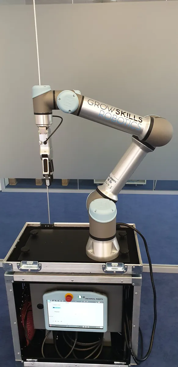
- Manufacturers publish tables: Universal Robots lists classic DH a, d and α for each of its arms, and notes that its ‘a’ is the same as Wikipedia’s ‘r’.
- Factory calibration: small errors in real link lengths and joint zeros are measured and corrected so that the robot’s model matches the metal.
- Simulation: before a new arm design is built, its kinematic table is checked in simulation at known poses.
- Your project: a validated table is what lets IK (Lessons 12–14) send the gripper exactly where you aim.
Bench build
Bench build: validate your arm’s table at the bench
Put your own measured table into dh_validate.ino. It stores the table on the Arduino, tells you which test pose to set, predicts the tip, and after you type the measured x y z it prints the error and PASS/FAIL (1 cm tolerance). The sketch moves nothing — you pose the arm with your Stage 6 firmware.
Measure
d₁ (table to shoulder axis), a₂, a₃ (shaft centre to shaft centre) and the tool length, with a vernier caliper.
Fill the table
Edit TABLE[] in the sketch (and the same numbers in
build_dh.py).Set up a measuring corner
Tape a ruler along the base x line and stand a steel ruler upright for height. Mark the base axis on the table.
Run the four poses
Pose the arm at each test pose with your Stage 6 firmware, measure the tip, type it in. Fix the table after any FAIL.
// dh_validate.ino - store your arm's DH table on the Arduino and validate it at the bench.
// The sketch drives NOTHING. Pose your Stage 6 arm with its own firmware at each test pose,
// measure the gripper tip with a ruler (cm from the base axis / table), type "x y z" in Serial
// Monitor, and the sketch prints the DH prediction, the error and PASS/FAIL.
// Same table as build_dh.py Part 2 (classic DH). Servo power rules still apply to your arm:
// separate 5-6 V high-current supply, common ground, never the Arduino 5 V pin.

struct DHRow { float offsetDeg, d, a, alphaDeg; };
const DHRow TABLE[5] = {          // cm and degrees - REPLACE with your measured table
  {0, 9.0, 0, 90},                // J1 base yaw
  {0, 0, 10.5, 0},                // J2 shoulder
  {0, 0, 9.8, 0},                 // J3 elbow
  {90, 0, 0, 90},                 // J4 wrist pitch (+90 offset)
  {0, 14.0, 0, 0},                // J5 wrist roll -> tip
};
const float TEST_POSES[4][5] = {{0, 0, 0, 0, 0}, {0, 90, 0, 0, 0}, {0, 90, -90, -90, 0}, {90, 0, 0, 0, 0}};
const float TOL_CM = 1.0;         // pass if the tip is within 1 cm
int current = 0;

void dhMul(float T[4][4], float th, float d, float a, float al) {
  float ct = cos(radians(th)), st = sin(radians(th)), ca = cos(radians(al)), sa = sin(radians(al));
  float A[4][4] = {{ct, -st * ca, st * sa, a * ct}, {st, ct * ca, -ct * sa, a * st}, {0, sa, ca, d}, {0, 0, 0, 1}};
  float R[4][4];
  for (int i = 0; i < 4; i++)
    for (int j = 0; j < 4; j++) {
      R[i][j] = 0;
      for (int k = 0; k < 4; k++) R[i][j] += T[i][k] * A[k][j];
    }
  memcpy(T, R, sizeof(R));
}

void predict(const float q[5], float tip[3]) {
  float T[4][4] = {{1, 0, 0, 0}, {0, 1, 0, 0}, {0, 0, 1, 0}, {0, 0, 0, 1}};
  for (int i = 0; i < 5; i++) dhMul(T, q[i] + TABLE[i].offsetDeg, TABLE[i].d, TABLE[i].a, TABLE[i].alphaDeg);
  for (int i = 0; i < 3; i++) tip[i] = T[i][3];
}

void announce() {
  float tip[3];
  predict(TEST_POSES[current], tip);
  Serial.print(F("Test pose ")); Serial.print(current + 1); Serial.print(F(": q = "));
  for (int i = 0; i < 5; i++) { Serial.print(TEST_POSES[current][i], 0); Serial.print(' '); }
  Serial.print(F(" DH tip (")); Serial.print(tip[0], 2); Serial.print(F(", "));
  Serial.print(tip[1], 2); Serial.print(F(", ")); Serial.print(tip[2], 2);
  Serial.println(F(")  -> pose the arm, measure, type x y z"));
}

void setup() {
  Serial.begin(115200);
  announce();
}

void loop() {
  if (!Serial.available()) return;
  float m[3];
  for (int i = 0; i < 3; i++) m[i] = Serial.parseFloat();
  while (Serial.available()) Serial.read();
  float tip[3];
  predict(TEST_POSES[current], tip);
  float err = sqrt(sq(tip[0] - m[0]) + sq(tip[1] - m[1]) + sq(tip[2] - m[2]));
  Serial.print(F("error ")); Serial.print(err, 2); Serial.println(err <= TOL_CM ? F(" cm  PASS") : F(" cm  FAIL - check signs, offsets, lengths"));
  current = (current + 1) % 4;
  announce();
}
Debugging
Debugging a new DH table
| Symptom | Likely cause | Fix |
|---|---|---|
| Fails ‘stretched out’ by tens of cm | Wrong α sign or a missing offset | Redraw z axes at the zero pose; re-apply the right-hand rule |
| Passes at J1 = 0, fails at J1 = 90° | Shoulder not on the base axis | Add the sideways/forward offset as a d or a value |
| Error equals one link’s error | One a or d mis-measured | Re-measure shaft centre to shaft centre |
| Published table gives ‘strange’ zero pose | Their zero pose is not your zero pose | Draw their zero pose; compare, don’t assume |
| Units look 100× off | Metres vs centimetres mixed | Write the unit in the table header |
| Your table differs from a classmate’s, both pass | Different but valid frame choices (e.g. parallel axes) | Fine — as long as each is validated and labelled |
Think
Think about it
Think
Kabir’s table passes the ‘stretched out’ test but fails ‘base turned 90°’. Which kind of mistake can only show up when J1 is not zero?
Experiment
Try it in the lab
About 45 minutes with build_dh.py, paper, a caliper and (optionally) your Stage 6 arm.
Experiment
Build, break and fix a table
You will need
- `build_dh.py` and Python 3
- Paper, pencil, set square
- Vernier caliper or steel ruler
- Optional: Stage 6 arm, Arduino UNO for `dh_validate.ino`
Steps
- Run `build_dh.py`. Do the UR5e hand check yourself on paper.
- Change the UR5e table to the UR3e values from Universal Robots’ page (Sources) and predict the new zero-pose flange before running.
- Draw your own arm at its zero pose and follow the seven steps to build its table.
- Put your numbers into Part 2 and the expected positions for the four test poses. Run until all PASS.
- Break it on purpose: flip one α, forget one offset. Note the worst error each time.
- If your arm is built, run `dh_validate.ino` at the four poses and record the measured errors.
Interactive · FK chain visualizer (3R planar educational)
Simplified 3R planar stand-in for Base→J1→J2→J3→EE. Full 6DOF adds wrist RPY on top of this position chain.
EE x
153.4
EE y
35.8
ᵇTₑ (planar) calculator
| 0.966 | -0.259 | 0.000 | 157.02 |
| 0.259 | 0.966 | 0.000 | 20.55 |
| 0.000 | 0.000 | 1.000 | 0.00 |
| 0.000 | 0.000 | 0.000 | 1.000 |
Sign and offset mistakes cause huge, obvious errors; length mistakes cause small ones roughly the size of the mistake. Four simple poses catch almost every table error before it reaches IK.
Knowledge check
Check your understanding
Knowledge check
1. One row of a DH table corresponds to…
2. You should draw the arm for building the table at…
3. The best first validation of a new table is…
4. For the UR5e at all zeros, x = a₂ + a₃. Using UR’s table that is about…
5. In build_dh.py, which mistake caused the biggest tip error?
6. Joint zero offsets belong…
7. Why keep the table as data with one FK loop?
Mini assignment
Hands-on assignment
Mini assignment
Validated DH table for your arm
Build, validate and document the classic DH table of your Stage 6 arm (or the example arm if yours is not built).
Deliverables
- Zero-pose side and top sketches with every z and x axis drawn.
- The DH table with units and the word ‘classic’ in the header, including offsets.
- A validation table: four poses, predicted tip, measured tip, error, PASS/FAIL.
- One ‘broken table’ experiment with the error it caused.
- Two sentences on what you would re-measure first if a test failed.
Do this, step by step
- Draw your arm in its zero pose, side view and top view, and mark every z axis (joint axis) and x axis (common normal).
- Fill in the DH table in
build_dh.py(theARMrows andOFFS) with your measured lengths. Run Part 2. - Pick four test poses (zero, pointing up, L-shape and one of your own). Predict each tip with a sketch before running the code.
- Measure the real tip for each pose (or use the example arm’s numbers) and mark PASS if the error is within your limit, FAIL if not.
- Break the table on purpose (swap one sign or drop one offset), rerun the tests, and note which poses fail and by how much.
Stuck? Hints, one at a time
- z axes go along joint axes; x axes go along the common normal from one z to the next.
- Test the easy poses (zero, pointing up) before the hard ones — they show sign mistakes quickly.
- If only one pose fails, re-measure the link used most in that pose first.
Challenges (pick by level)
- 🟢 Easy: Hand-check the UR5e ‘pointing up’ height from the table values.
- 🟢 Easy: Add a fifth test pose to Part 2 and work out its expected tip with a sketch.
- 🟡 Medium: Load the UR16e table from Universal Robots’ page and compute its zero-pose flange.
- 🟠 Hard-ish: Write a function that prints every joint origin for a pose and plot the stick figure with matplotlib.
- 🔴 Hard: Write the table for an arm whose shoulder is 2 cm in front of the base axis and prove it with the four test poses.
- ⚫ Research: Read how industrial robots are calibrated (kinematic calibration) and list which table numbers are usually corrected.
Next step
Your table now gives you the full 4 × 4 matrix of the gripper, not just a position. In Lesson 10 — End-Effector Pose Calculation you will read that matrix: where the gripper is, which way it points, and how to turn it into numbers a controller can use.
Look back: Lesson 8: Denavit–Hartenberg Parameters. Next: Lesson 10: End-Effector Pose Calculation. Related: Stage 6 — 6DOF Arm and Stage 12 — Simulation & Digital Twin.
Sources
- Universal Robots — DH parameters for calculations of kinematics and dynamics — published classic DH tables (UR5e: d₁ 0.1625, a₂ −0.425, a₃ −0.3922, d₄ 0.1333, d₅ 0.0997, d₆ 0.0996 m).
- Wikipedia — Denavit–Hartenberg parameters — frame rules (z on the joint axis, x on the common normal, free choice for parallel axes) and the classic DH matrix.
- Modern Robotics — K. M. Lynch & F. C. Park (book home page, free preprint) — Forward Kinematics chapter and Appendix C (Denavit–Hartenberg Parameters).
- Lessons 7–8 of this stage — the example arm and its classic DH table.
- Photos: Wikimedia Commons (credits under each image).
Self-attested for now — keep artifacts in your lab notebook.
Complete
Today's goal
0 of 1 done today
Mark this lesson complete when you have worked the experiment, knowledge check, and assignment (even roughly).