
Kinematics & Inverse Kinematics · Lesson 07
Forward Kinematics — 6DOF Arm
Est. 60–80 min
Why
Why this lesson matters
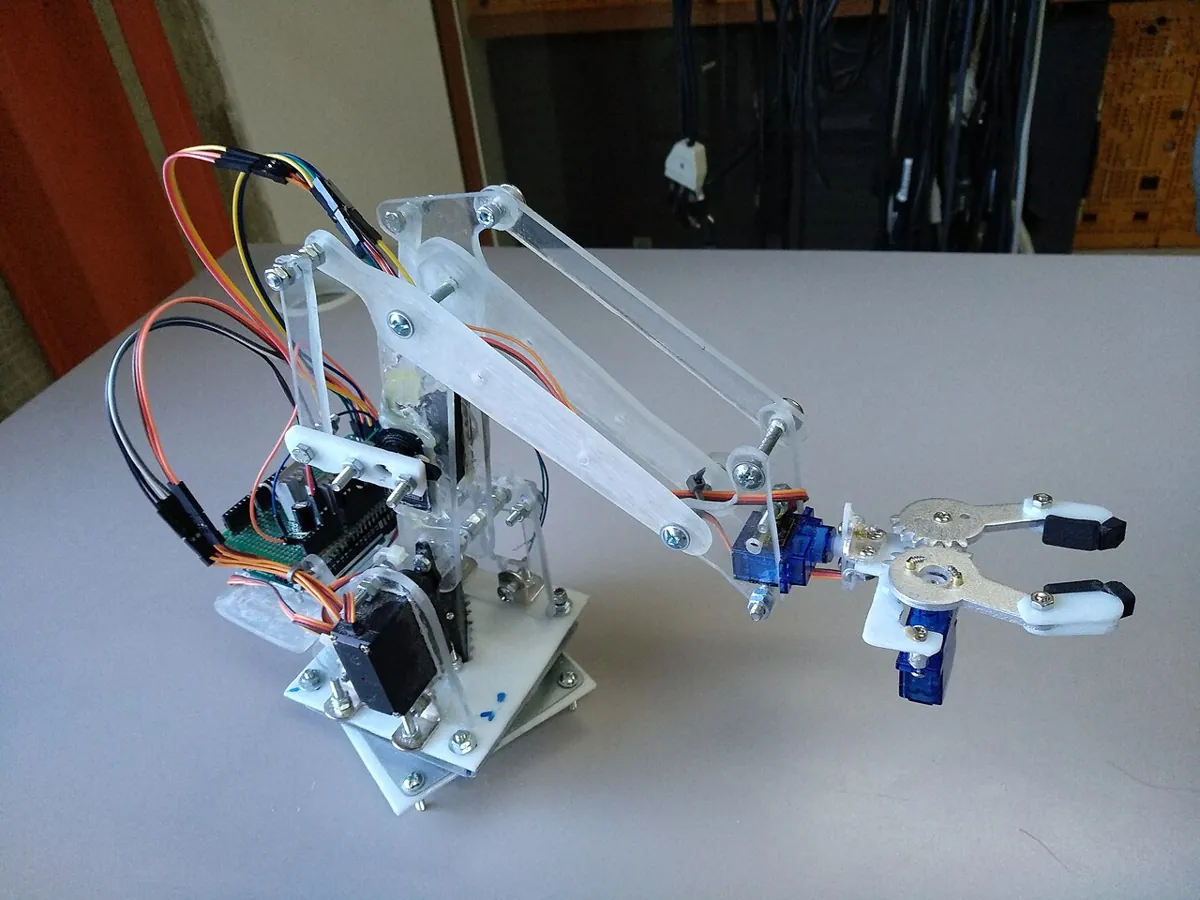
In Lesson 6 you built FK for a planar arm. A hobby ‘6DOF’ arm like the one from Stage 6 is the same idea in 3D: a base yaw that turns the whole arm about the vertical, three pitch joints (shoulder, elbow, wrist pitch) that work in one vertical plane, a wrist roll, and a gripper. With 4 × 4 transforms (Lesson 4) you can chain them all and get the gripper tip in 3D.
By the end of this lesson you will be able to: write the FK chain for a base-yaw + shoulder + elbow + wrist-pitch + wrist-roll arm; compute the wrist centre and the gripper tip in 3D; explain why wrist roll does not move the tip and why the wrist centre depends only on J1–J3; use FK as a safety check before sending angles; and measure your own arm’s link lengths for the model.
Concept
FK for your Stage 6 arm
The joints (same names as Stage 6)
| Joint | Turns about | What it does to the tip |
|---|---|---|
| J1 base yaw | The vertical axis (z) | Swings the whole arm round; distance from the base axis stays the same |
| J2 shoulder pitch | A horizontal axis | Lifts the upper arm |
| J3 elbow pitch | A horizontal axis | Bends the forearm |
| J4 wrist pitch | A horizontal axis | Tilts the gripper up or down |
| J5 wrist roll | The gripper’s own long axis | Spins the gripper — the tip does not move |
| Gripper (J6) | — | Opens/closes; treated as a tool, not part of the position chain |
The chain
T_B_wrist = Rz(J1) · Tz(D1) · Ry(−J2) · Tx(L2) · Ry(−J3) · Tx(L3)
T_B_tip   = T_B_wrist · Ry(−J4) · Rx(J5) · Tx(L4)

D1 = table to shoulder axis, L2 = shoulder to elbow, L3 = elbow to wrist pitch,
L4 = wrist pitch to gripper tip.  Ry(−J) is used so that +J lifts the arm.
Read it like Lesson 6: turn the base, go up to the shoulder, pitch, go along the upper arm, pitch, go along the forearm — that is the wrist centre. Then pitch the wrist, roll, and go out to the gripper tip. Because J2, J3 and J4 all turn about parallel horizontal axes, inside the arm’s vertical plane their angles simply add up, exactly like the planar arm.
Two useful facts
- The wrist centre depends only on J1, J2, J3. J4 and J5 sit *at* the wrist, so they change where the gripper points, not where the wrist is. Lesson 13–14’s IK uses this to split the problem in two.
- Wrist roll does not move the tip when the tip lies on the roll axis — it only turns the gripper fingers.
Visual
Visualise it: the position chain
Simplified planar view of the shoulder → elbow → wrist chain inside the arm’s vertical plane. Base yaw (J1) then swings this whole plane round.
Interactive · FK chain visualizer (3R planar educational)


Simplified 3R planar stand-in for Base→J1→J2→J3→EE. Full 6DOF adds wrist RPY on top of this position chain.
EE x
153.4
EE y
35.8
ᵇTₑ (planar) calculator
| 0.966 | -0.259 | 0.000 | 157.02 |
| 0.259 | 0.966 | 0.000 | 20.55 |
| 0.000 | 0.000 | 1.000 | 0.00 |
| 0.000 | 0.000 | 0.000 | 1.000 |
Code lab
Code lab: fk6.py
fk6.py builds the chain above with plain-Python 4 × 4 matrices. For each set of joint angles it prints the wrist centre, the gripper tip and the direction the gripper points (the tool’s x axis). The ‘What to notice’ part checks the two useful facts and does a safety check.
# fk6.py - forward kinematics of a typical hobby "6DOF" arm in 3D, with 4x4 transforms.
# Joints (same names as the Stage 6 course): J1 base yaw, J2 shoulder pitch, J3 elbow pitch,
# J4 wrist pitch, J5 wrist roll. The gripper (J6) opens/closes and does not move the tip frame.
# EXAMPLE link sizes in cm - measure YOUR arm (shaft centre to shaft centre) and change them.
import math

D1 = 9.0     # table -> shoulder axis height
L2 = 10.5    # shoulder axis -> elbow axis
L3 = 9.8     # elbow axis -> wrist-pitch axis
L4 = 14.0    # wrist-pitch axis -> gripper tip (tool)


def Rz(d):
    c, s = math.cos(math.radians(d)), math.sin(math.radians(d))
    return [[c, -s, 0, 0], [s, c, 0, 0], [0, 0, 1, 0], [0, 0, 0, 1]]


def Ry(d):
    c, s = math.cos(math.radians(d)), math.sin(math.radians(d))
    return [[c, 0, s, 0], [0, 1, 0, 0], [-s, 0, c, 0], [0, 0, 0, 1]]


def Rx(d):
    c, s = math.cos(math.radians(d)), math.sin(math.radians(d))
    return [[1, 0, 0, 0], [0, c, -s, 0], [0, s, c, 0], [0, 0, 0, 1]]


def Tx(a):
    return [[1, 0, 0, a], [0, 1, 0, 0], [0, 0, 1, 0], [0, 0, 0, 1]]


def Tz(a):
    return [[1, 0, 0, 0], [0, 1, 0, 0], [0, 0, 1, a], [0, 0, 0, 1]]


def mul(*Ms):
    out = [[float(i == j) for j in range(4)] for i in range(4)]
    for M in Ms:
        out = [[sum(out[i][k] * M[k][j] for k in range(4)) for j in range(4)] for i in range(4)]
    return out


def fk(q):
    """q = (J1..J5) in degrees. Pitch joints use Ry(-q) so that +q LIFTS the arm."""
    j1, j2, j3, j4, j5 = q
    T_wrist = mul(Rz(j1), Tz(D1), Ry(-j2), Tx(L2), Ry(-j3), Tx(L3))   # wrist-pitch axis
    T_tool = mul(T_wrist, Ry(-j4), Rx(j5), Tx(L4))                     # gripper tip
    return T_wrist, T_tool


def p(T):
    return f"({T[0][3] + 0.0:6.2f}, {T[1][3] + 0.0:6.2f}, {T[2][3] + 0.0:6.2f})"


def x_axis(T):                                   # which way the gripper points
    return f"({T[0][0] + 0.0:5.2f}, {T[1][0] + 0.0:5.2f}, {T[2][0] + 0.0:5.2f})"


print(f"Example arm: D1 {D1}, L2 {L2}, L3 {L3}, L4 {L4} cm\n")
print(f"{'J1..J5 (deg)':<26} {'wrist centre':>24} {'gripper tip':>24}  tip points along")
for q in ((0, 0, 0, 0, 0), (0, 90, 0, 0, 0), (0, 45, -45, -45, 0), (90, 45, -45, -45, 0),
          (30, 70, -80, -80, 0), (30, 70, -80, -80, 90)):
    Tw, Tt = fk(q)
    print(f"{str(q):<26} {p(Tw):>24} {p(Tt):>24}  {x_axis(Tt)}")

print("\nWhat to notice")
Tw1, Tt1 = fk((30, 70, -80, -80, 0))
Tw2, Tt2 = fk((30, 70, -80, -80, 90))
same = all(abs(Tt1[i][3] - Tt2[i][3]) < 1e-9 for i in range(3))
print(f"- wrist roll J5 from 0° to 90°: tip position unchanged? {same}  (roll spins the tool about its own axis)")
moved = any(abs(fk((30, 70, -80, a, 0))[0][i][3] - Tw1[i][3]) > 1e-9 for a in (-30, 0, 30) for i in range(3))
print(f"- wrist pitch J4 moves the wrist centre? {moved}  (wrist centre depends on J1-J3 only)")
rs = {round(math.hypot(fk((j1, 70, -80, -80, 0))[1][0][3], fk((j1, 70, -80, -80, 0))[1][1][3]), 2) for j1 in (-60, 0, 30, 90)}
print(f"- J1 only swings the arm about the vertical: tip distance from the base axis for J1 = -60, 0, 30, 90 -> {sorted(rs)} cm")
z = fk((30, 60, -90, -60, 0))[1][2][3]
print(f"- safety check before moving: q = (30, 60, -90, -60, 0) puts the tip at z = {z:.2f} cm -> {'BELOW THE TABLE, do not send' if z < 0 else 'ok'}")
Output (run with python3 fk6.py)
Example arm: D1 9.0, L2 10.5, L3 9.8, L4 14.0 cm

J1..J5 (deg)                           wrist centre              gripper tip  tip points along
(0, 0, 0, 0, 0)            ( 20.30,   0.00,   9.00) ( 34.30,   0.00,   9.00)  ( 1.00,  0.00,  0.00)
(0, 90, 0, 0, 0)           (  0.00,   0.00,  29.30) (  0.00,   0.00,  43.30)  ( 0.00,  0.00,  1.00)
(0, 45, -45, -45, 0)       ( 17.22,   0.00,  16.42) ( 27.12,   0.00,   6.53)  ( 0.71,  0.00, -0.71)
(90, 45, -45, -45, 0)      (  0.00,  17.22,  16.42) (  0.00,  27.12,   6.53)  ( 0.00,  0.71, -0.71)
(30, 70, -80, -80, 0)      ( 11.47,   6.62,  17.17) ( 11.47,   6.62,   3.17)  ( 0.00,  0.00, -1.00)
(30, 70, -80, -80, 90)     ( 11.47,   6.62,  17.17) ( 11.47,   6.62,   3.17)  ( 0.00,  0.00, -1.00)

What to notice
- wrist roll J5 from 0° to 90°: tip position unchanged? True  (roll spins the tool about its own axis)
- wrist pitch J4 moves the wrist centre? False  (wrist centre depends on J1-J3 only)
- J1 only swings the arm about the vertical: tip distance from the base axis for J1 = -60, 0, 30, 90 -> [13.24] cm
- safety check before moving: q = (30, 60, -90, -60, 0) puts the tip at z = -0.81 cm -> BELOW THE TABLE, do not send
Try it: treat the three links as shoulder → elbow → wrist in the arm’s vertical plane (simplified). Find settings where the tool points straight down.
Interactive · FK chain visualizer (3R planar educational)
Simplified 3R planar stand-in for Base→J1→J2→J3→EE. Full 6DOF adds wrist RPY on top of this position chain.
EE x
153.4
EE y
35.8
ᵇTₑ (planar) calculator
| 0.966 | -0.259 | 0.000 | 157.02 |
| 0.259 | 0.966 | 0.000 | 20.55 |
| 0.000 | 0.000 | 1.000 | 0.00 |
| 0.000 | 0.000 | 0.000 | 1.000 |
Real world
6DOF FK in the real world
- Industrial arms: controllers use 6-joint FK to show the tool pose and check limits.
- Many industrial arms have a ‘spherical wrist’: the last three joint axes meet at one point, so the wrist centre depends only on the first three joints — the same split you saw in
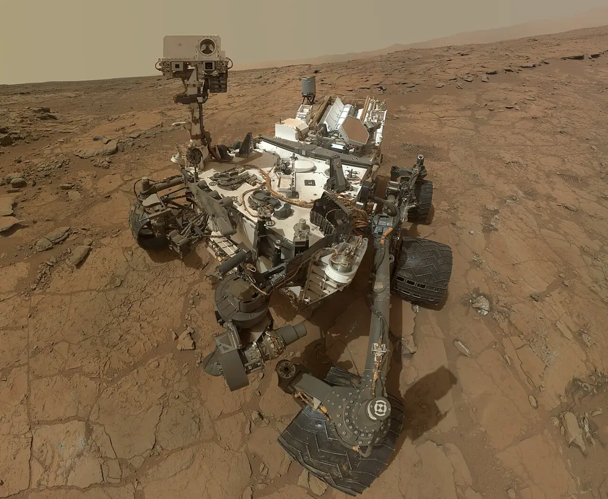
fk6.py. - Space and planetary arms: a rover’s arm must know exactly where its tools and cameras are before touching a rock.
- Simulation: digital twins of arms in ROS and simulators draw every link from FK.
Bench build
Bench build: measure your arm and check FK
This bench build does not add new wiring. You measure your Stage 6 arm, put the numbers into the model, pose the arm with its own firmware, and check the FK answer with a ruler. arm_fk_calculator.ino runs the same FK on an Arduino (it drives nothing) so you can check numbers at the bench without a laptop running Python.
Measure D1
Table to the shoulder servo’s shaft centre, straight up.
Measure L2 and L3
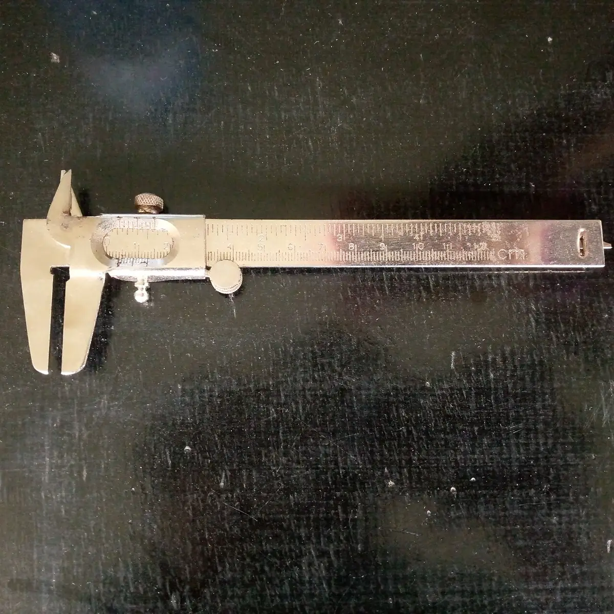
Shaft centre to shaft centre: shoulder → elbow, elbow → wrist pitch. Use a vernier caliper or a steel ruler.
Measure L4
Wrist-pitch shaft centre to the point between the gripper fingertips.
Check signs and zeros
Command each joint to 0°, then +20°. Write down which way it moves. Fix signs in the model if needed.
Pose and compare
Send (0, 45, −45, −45, 0) and (30, 70, −80, −80, 0) with your Stage 6 firmware. Measure the tip with a ruler from the base axis and the table. Compare with
fk6.pyor the calculator sketch.
// arm_fk_calculator.ino - a forward-kinematics calculator that runs ON the Arduino.
// It does NOT move any servo. Pose your Stage 6 arm with its own firmware, type the same five
// joint angles here (e.g. "30 70 -80 -80 0"), and compare the printed tip with a ruler.
// Same model as fk6.py: J1 base yaw, J2 shoulder pitch, J3 elbow pitch, J4 wrist pitch, J5 roll.
// Safety: this sketch drives nothing. Your arm's servos stay on their own high-current supply
// (Stage 6 power rules); never power servos from the Arduino 5 V pin.
const float D1 = 9.0, L2 = 10.5, L3 = 9.8, L4 = 14.0;   // cm - MEASURE YOUR ARM

void setup() {
  Serial.begin(115200);
  Serial.println(F("Type J1 J2 J3 J4 J5 in degrees, e.g. 30 70 -80 -80 0"));
}

void loop() {
  if (!Serial.available()) return;
  float j[5];
  for (int i = 0; i < 5; i++) j[i] = Serial.parseFloat();
  while (Serial.available()) Serial.read();
  // In the vertical plane of the arm, the pitch angles add up (like the planar FK in Lesson 6)
  float a2 = radians(j[1]), a23 = radians(j[1] + j[2]), a234 = radians(j[1] + j[2] + j[3]);
  float rWrist = L2 * cos(a2) + L3 * cos(a23);          // horizontal distance from the base axis
  float zWrist = D1 + L2 * sin(a2) + L3 * sin(a23);
  float r = rWrist + L4 * cos(a234), z = zWrist + L4 * sin(a234);
  // J1 swings that plane about the vertical axis. J5 (roll) does not move the tip.
  float yaw = radians(j[0]);
  Serial.print(F("wrist (")); Serial.print(rWrist * cos(yaw), 2); Serial.print(F(", "));
  Serial.print(rWrist * sin(yaw), 2); Serial.print(F(", ")); Serial.print(zWrist, 2);
  Serial.print(F(")  tip (")); Serial.print(r * cos(yaw), 2); Serial.print(F(", "));
  Serial.print(r * sin(yaw), 2); Serial.print(F(", ")); Serial.print(z, 2); Serial.print(F(")"));
  Serial.println(z < 0 ? F("  WARNING: below the table!") : F(""));
}
Debugging
Debugging 6DOF FK
| Symptom | Likely cause | Fix |
|---|---|---|
| Tip height wrong by the same amount everywhere | D1 wrong | Re-measure table to shoulder axis |
| Tip goes up in the model, down on the arm | Pitch sign flipped | Use Ry(+J) instead of Ry(−J) for that joint |
| Error grows with reach | A joint zero is off by a few degrees | Re-zero with a set square |
| Error only when J1 ≠ 0 | Shoulder not on the base axis (sideways or forward offset) | Add a Tx/Ty offset after Rz(J1) |
| Changing J5 moves the tip | Tip is not on the roll axis (gripper offset) | Add the offset after Rx(J5) and re-measure L4 |
| Model fine, real arm sags under load | Servo deflection, not kinematics | Lighter payload or stronger servos (Stage 7) |
Think
Think about it
Think
Fatima says, “Your arm has five joints but the tip only has three position numbers (x, y, z). So two joints are useless.” Is she right?
Experiment
Try it in the lab
About 45 minutes with fk6.py, a caliper or ruler, and your Stage 6 arm (or the photos and example numbers if your arm is not built yet).
Experiment
FK for your own arm
You will need
- `fk6.py` and Python 3
- Your Stage 6 arm and its firmware (optional)
- Vernier caliper or steel ruler, set square
- Optional: Arduino UNO for `arm_fk_calculator.ino`
Steps
- Run `fk6.py` with the example sizes and check the all-zeros and straight-up rows by hand.
- Measure your arm and put your D1, L2, L3, L4 into the file. Run again.
- Add a pose of your own that points the gripper straight down 5 cm above the table. Use FK to find it by trying values.
- Add a check that prints a warning if the **elbow** (not just the tip) goes below the table.
- If your arm is built: pose it at two of your rows and measure the tip. Record the error.
- In the visualiser, set the three links so the tool points straight down, and compare with your `fk6.py` pose.
Interactive · FK chain visualizer (3R planar educational)
Simplified 3R planar stand-in for Base→J1→J2→J3→EE. Full 6DOF adds wrist RPY on top of this position chain.
EE x
153.4
EE y
35.8
ᵇTₑ (planar) calculator
| 0.966 | -0.259 | 0.000 | 157.02 |
| 0.259 | 0.966 | 0.000 | 20.55 |
| 0.000 | 0.000 | 1.000 | 0.00 |
| 0.000 | 0.000 | 0.000 | 1.000 |
The 3D chain behaves like the planar chain inside the arm’s vertical plane, with J1 swinging that plane. J4 and J5 change where the gripper points but not where the wrist is. FK makes ‘will this pose hit the table?’ a quick calculation.
Knowledge check
Check your understanding
Knowledge check
1. In the example arm, which joint swings the whole arm about the vertical axis?
2. With all joints at 0°, the example tip is at (34.30, 0, 9.00). Where does 34.30 come from?
3. Changing wrist roll J5 from 0° to 90° in fk6.py…
4. The wrist centre depends on…
5. For (30, 70, −80, −80, 0) the gripper points straight down. Why?
6. fk6.py says a pose puts the tip at z = −0.81 cm. You should…
7. Your real arm’s error grows the further it reaches. The most likely cause is…
Mini assignment
Hands-on assignment
Mini assignment
FK model card for your arm
Make a one-page FK model card for your Stage 6 arm that someone else could use.
Deliverables
- A side-view and a top-view sketch with D1, L2, L3, L4, any offsets and every joint’s positive direction.
- The FK chain written in Rz/Ry/Rx/Tx/Tz steps for your arm.
- A table of measured link lengths and how you measured them.
- Three poses: FK prediction vs measured tip, with the error.
- A list of ‘forbidden’ poses your FK check would block (tip or elbow below the table).
Do this, step by step
- Measure D1, L2, L3 and L4 on your Stage 6 arm (axis to axis), and write each joint’s positive direction on a side-view sketch.
- Put your numbers into
fk6.pyand run the all-zeros and straight-up poses first. Check those by hand — they are just sums of lengths. - Choose three more poses, run FK, then set the real arm to them slowly and measure the tip with a ruler.
- Record prediction vs measured tip and the error for each pose.
- List at least two ‘forbidden’ poses where FK puts the tip or elbow below the table, and add a check to
fk6.pythat prints a warning for them.
Stuck? Hints, one at a time
- Start with the all-zeros pose — the tip should be a simple sum of lengths.
- J1 only swings the arm round the base, so changing it must not change the tip height.
- If one pose is badly off, check that joint’s positive direction first.
Challenges (pick by level)
- 🟢 Easy: Compute the all-zeros and straight-up tips for your own link lengths by hand.
- 🟢 Easy: Change J1 to 45° in one row and check the tip is only swung round.
- 🟡 Medium: Make
fk6.pyalso print the elbow position and warn if it is below the table. - 🟠 Hard-ish: Add a 2 cm sideways wrist offset (Ty after the roll) and show that J5 now moves the tip.
- 🔴 Hard: Sweep J2, J3 in 10° steps (J1 = 0, J4 = −J2 − J3) and plot every tip point: the side-view workspace.
- ⚫ Research: Look up what a ‘spherical wrist’ is and find one industrial arm that has it.
Next step
Writing chains by hand works, but people use a standard recipe so everyone gets the same frames. In Lesson 8 — Denavit–Hartenberg Parameters you learn that recipe.
Look back: Lesson 6: Forward Kinematics — Concept. Next: Lesson 8: Denavit–Hartenberg Parameters. Related: Stage 6 — 6DOF Arm and Stage 12 — Simulation & Digital Twin.
Sources
- Wikipedia — Forward kinematics — computing the end-effector position from joint parameters with the robot’s kinematic equations.
- Wikipedia — Inverse kinematics — many industrial 6DOF robots have a ‘spherical wrist’ (last three joint axes intersect).
- Modern Robotics — K. M. Lynch & F. C. Park (book home page, free preprint) — chapters on Rigid-Body Motions and Forward Kinematics.
- Stage 6 course on this site — joint naming (J1 base yaw … J5 wrist roll) and servo power rules.
- Photos: Wikimedia Commons (credits under each image).
Self-attested for now — keep artifacts in your lab notebook.
Complete
Today's goal
0 of 1 done today
Mark this lesson complete when you have worked the experiment, knowledge check, and assignment (even roughly).