
Kinematics & Inverse Kinematics · Lesson 10
End-Effector Pose Calculation
Est. 60–80 min
Why
Why this lesson matters
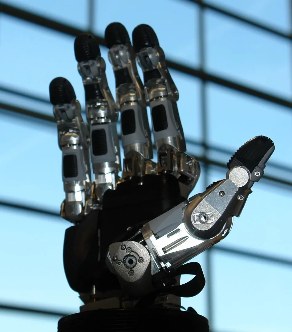
Multiplying the DH rows (Lessons 8–9) gives the full end-effector pose: a rotation R (3 × 3) and a position p (3 × 1). The position says *where* the gripper is; the rotation says *which way* it points and how it is turned. Pick-and-place, drawing, welding, pouring — every real job needs both.
By the end of this lesson you will be able to: read p and the three axis columns of R from a computed pose; find the gripper’s approach direction and its tilt below the horizontal; convert R to yaw–pitch–roll angles and back; find the position of a tool point (like a pen tip) held by the gripper; express an object in the gripper’s own frame using the inverse transform; and recognise gimbal lock when angle sets stop working.
Concept
Reading T = [R p; 0 1]
The four columns of T
| Column | What it is | Everyday meaning |
|---|---|---|
| 1st (x₅) | Gripper’s x axis, in base coordinates | The direction the fingers open across |
| 2nd (y₅) | Gripper’s y axis | The third direction (right-hand rule) |
| 3rd (z₅) | Gripper’s z axis — the approach direction | The way the gripper is pointing, like your index finger |
| 4th (p) | Tip position | Where the fingertips are, in cm from the base |
Three things you will do with a pose
- Describe the direction with three angles. Yaw–pitch–roll (Tait–Bryan z-y′-x″) is common: R = Rz(yaw) · Ry(pitch) · Rx(roll). From R: pitch = atan2(−r₃₁, √(r₁₁² + r₂₁²)), yaw = atan2(r₂₁, r₁₁), roll = atan2(r₃₂, r₃₃).
- Find a tool point. A pen sticking 3 cm out along the approach axis is at T · (0, 0, 3, 1). The same works for a camera or a suction cup.
- See the world from the gripper. T⁻¹ = [Rᵀ, −Rᵀp; 0 1]. Multiply an object’s base-frame position by T⁻¹ and you get ‘how far ahead and how far to the side’ of the gripper it is.
Visual
Visualise it: position and pointing direction
In the arm’s vertical plane, the tool position is the chain of links and the tool direction is the sum of the joint angles — the planar view of p and the approach column.
Interactive · FK chain visualizer (3R planar educational)


Simplified 3R planar stand-in for Base→J1→J2→J3→EE. Full 6DOF adds wrist RPY on top of this position chain.
EE x
153.4
EE y
35.8
ᵇTₑ (planar) calculator
| 0.966 | -0.259 | 0.000 | 157.02 |
| 0.259 | 0.966 | 0.000 | 20.55 |
| 0.000 | 0.000 | 1.000 | 0.00 |
| 0.000 | 0.000 | 0.000 | 1.000 |
Code lab
Code lab: ee_pose.py
ee_pose.py uses the classic DH table from Lesson 9 to compute T for one pose and then reads it: position, the three axes, the approach tilt and heading, yaw–pitch–roll (and a rebuild check), a pen tip, a cup seen from the gripper, and a gimbal-lock case.
# ee_pose.py - read the end-effector pose T = [R p; 0 1] from the DH chain (Lessons 8-9).
# Where is the gripper (p)? Which way does it point (columns of R)? What are its yaw/pitch/roll?
# Where is a pen held in the gripper? Where is a cup, as seen from the gripper?
# EXAMPLE arm in cm, classic DH, same table as build_dh.py.
import math

D1, L2, L3, L4 = 9.0, 10.5, 9.8, 14.0
ARM = [(0, D1, 0, 90), (0, 0, L2, 0), (0, 0, L3, 0), (90, 0, 0, 90), (0, L4, 0, 0)]  # (offset, d, a, alpha) deg


def dh(th, d, a, al):
    ct, st = math.cos(math.radians(th)), math.sin(math.radians(th))
    ca, sa = math.cos(math.radians(al)), math.sin(math.radians(al))
    return [[ct, -st * ca, st * sa, a * ct], [st, ct * ca, -ct * sa, a * st], [0, sa, ca, d], [0, 0, 0, 1]]


def mul(A, B):
    return [[sum(A[i][k] * B[k][j] for k in range(4)) for j in range(4)] for i in range(4)]


def fk(q):
    T = [[float(i == j) for j in range(4)] for i in range(4)]
    for qi, (off, d, a, al) in zip(q, ARM):
        T = mul(T, dh(qi + off, d, a, al))
    return T


def clean(v, nd=3):
    return round(v, nd) + 0.0


def vec(v):
    return "(" + ", ".join(f"{clean(x):6.3f}" for x in v) + ")"


def ypr_zyx(R):
    """Yaw-pitch-roll (Tait-Bryan z-y'-x'') from R, in degrees. R = Rz(yaw) Ry(pitch) Rx(roll)."""
    pitch = math.atan2(-R[2][0], math.hypot(R[0][0], R[1][0]))
    if abs(math.cos(pitch)) < 1e-6:                      # gimbal lock: yaw and roll not separable
        return None, math.degrees(pitch), None
    yaw = math.atan2(R[1][0], R[0][0])
    roll = math.atan2(R[2][1], R[2][2])
    return math.degrees(yaw), math.degrees(pitch), math.degrees(roll)


def apply(T, pt):
    return [sum(T[i][k] * v for k, v in enumerate(list(pt) + [1])) for i in range(3)]


def inverse(T):          # [R p]^-1 = [R^T  -R^T p]
    Rt = [[T[j][i] for j in range(3)] for i in range(3)]
    p = [T[i][3] for i in range(3)]
    mp = [-sum(Rt[i][k] * p[k] for k in range(3)) for i in range(3)]
    return [Rt[0] + [mp[0]], Rt[1] + [mp[1]], Rt[2] + [mp[2]], [0, 0, 0, 1]]


q = (30, 60, -60, -30, 0)
T = fk(q)
R = [row[:3] for row in T[:3]]
print(f"Pose q = {q} deg\n")
print("T (rotation | position, cm):")
for row in T:
    print("  [" + "  ".join(f"{clean(v):7.3f}" for v in row) + " ]")
print("\nReading it")
print("  p  = tip position          ", vec([T[i][3] for i in range(3)]), "cm")
print("  x5 = 'fingers open' axis   ", vec([R[i][0] for i in range(3)]))
print("  y5 = third axis            ", vec([R[i][1] for i in range(3)]))
print("  z5 = approach (gripper)    ", vec([R[i][2] for i in range(3)]))
tilt = math.degrees(math.asin(-R[2][2]))
print(f"  approach points {abs(tilt):.1f} deg {'below' if tilt > 0 else 'above'} the horizontal, "
      f"heading {math.degrees(math.atan2(R[1][2], R[0][2])):.1f} deg from base x")

y, pch, r = ypr_zyx(R)
print(f"\nYaw-pitch-roll (z-y'-x''): yaw {y:.1f}, pitch {pch:.1f}, roll {r:.1f} deg")
c = lambda d: math.cos(math.radians(d))
s = lambda d: math.sin(math.radians(d))
Rz = [[c(y), -s(y), 0], [s(y), c(y), 0], [0, 0, 1]]
Ry = [[c(pch), 0, s(pch)], [0, 1, 0], [-s(pch), 0, c(pch)]]
Rx = [[1, 0, 0], [0, c(r), -s(r)], [0, s(r), c(r)]]
m3 = lambda A, B: [[sum(A[i][k] * B[k][j] for k in range(3)) for j in range(3)] for i in range(3)]
Rb = m3(m3(Rz, Ry), Rx)
print("  rebuilding R from the three angles matches:", all(abs(Rb[i][j] - R[i][j]) < 1e-9 for i in range(3) for j in range(3)))

pen = apply(T, (0, 0, 3.0))
print("\nA pen sticking 3 cm out of the gripper along z5 ->  pen tip at", vec(pen), "cm (base frame)")
cup_base = (22.0, 14.0, 4.0)
cup_in_gripper = apply(inverse(T), cup_base)
print("A cup at", vec(cup_base), "cm (base) is at", vec(cup_in_gripper), "cm in the GRIPPER frame")
print("  -> z5 component = how far ahead along the approach; x5/y5 = how far off to the side")

print("\nGimbal-lock check: arm stretched out level, q = (0, 0, 0, 0, 0)")
Rd = [row[:3] for row in fk((0, 0, 0, 0, 0))[:3]]
yd, pd, rd = ypr_zyx(Rd)
print("  x5 =", vec([Rd[i][0] for i in range(3)]), " (points straight up)  z5 =", vec([Rd[i][2] for i in range(3)]))
if yd is None:
    print(f"  pitch = {pd:.1f} deg -> yaw and roll cannot be separated (gimbal lock); keep using R itself")
else:
    print(f"  yaw {yd:.1f}, pitch {pd:.1f}, roll {rd:.1f}")
Output (run with python3 ee_pose.py)
Pose q = (30, 60, -60, -30, 0) deg

T (rotation | position, cm):
  [  0.433    0.500    0.750   23.534 ]
  [  0.250   -0.866    0.433   13.587 ]
  [  0.866    0.000   -0.500   11.093 ]
  [  0.000    0.000    0.000    1.000 ]

Reading it
  p  = tip position           (23.534, 13.587, 11.093) cm
  x5 = 'fingers open' axis    ( 0.433,  0.250,  0.866)
  y5 = third axis             ( 0.500, -0.866,  0.000)
  z5 = approach (gripper)     ( 0.750,  0.433, -0.500)
  approach points 30.0 deg below the horizontal, heading 30.0 deg from base x

Yaw-pitch-roll (z-y'-x''): yaw 30.0, pitch -60.0, roll 180.0 deg
  rebuilding R from the three angles matches: True

A pen sticking 3 cm out of the gripper along z5 ->  pen tip at (25.784, 14.886,  9.593) cm (base frame)
A cup at (22.000, 14.000,  4.000) cm (base) is at (-6.704, -1.124,  2.575) cm in the GRIPPER frame
  -> z5 component = how far ahead along the approach; x5/y5 = how far off to the side

Gimbal-lock check: arm stretched out level, q = (0, 0, 0, 0, 0)
  x5 = ( 0.000,  0.000,  1.000)  (points straight up)  z5 = ( 1.000,  0.000,  0.000)
  pitch = -90.0 deg -> yaw and roll cannot be separated (gimbal lock); keep using R itself
Try it: in the arm’s vertical plane, the tool direction is the sum of the joint angles. Set the three links so the tool points 30° below the horizontal, like the pose in ee_pose.py.
Interactive · FK chain visualizer (3R planar educational)
Simplified 3R planar stand-in for Base→J1→J2→J3→EE. Full 6DOF adds wrist RPY on top of this position chain.
EE x
153.4
EE y
35.8
ᵇTₑ (planar) calculator
| 0.966 | -0.259 | 0.000 | 157.02 |
| 0.259 | 0.966 | 0.000 | 20.55 |
| 0.000 | 0.000 | 1.000 | 0.00 |
| 0.000 | 0.000 | 0.000 | 1.000 |
Real world
End-effector poses in the real world
- Pick and place: the gripper must approach from above (approach = −z) at a known position; both parts of the pose matter.
- Welding and painting: the torch or spray gun must keep a set angle to the surface as it moves.
- Cameras on arms: to know what a wrist camera sees, you need its full pose, not just where it is.
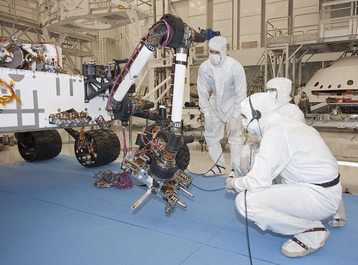
- Planetary arms: a rover’s arm carries instruments that must be pressed against a rock face at the right angle.
Bench build
Bench build: check the gripper’s tilt with an IMU
Position is easy to check with a ruler. Orientation is harder — so use a sensor. Tape an MPU-6050 board flat on the gripper with its x arrow along the approach direction. Pose the arm with your Stage 6 firmware, type the same five angles, and gripper_tilt_check.ino compares FK’s approach elevation (J2 + J3 + J4) with the elevation the accelerometer measures from gravity.
Wire the IMU
GND → GND, SDA → A4, SCL → A5. VCC to 5 V only if your GY-521 board has an on-board 3.3 V regulator; otherwise 3.3 V. Use a light ribbon cable with slack.
Mount it
Double-sided tape, flat on the gripper body, x arrow pointing out along the fingers.
Test three poses
Level (approach horizontal), 30° down, and pointing straight down. Hold still for a second before typing the angles.
Read the difference
Within about 5° is good for hobby servos. A constant difference at every pose means the IMU is mounted at a slight angle; a difference that changes means a joint zero or sign is off.
// gripper_tilt_check.ino - check the ORIENTATION part of your FK with a real sensor.
// Tape an MPU-6050 (GY-521 board) flat on the gripper with its x arrow pointing along the
// gripper (the approach direction, z5 in ee_pose.py). Pose the arm with your Stage 6 firmware,
// type the same five joint angles here ("30 60 -60 -30 0"), and compare:
//   FK elevation of the approach = J2 + J3 + J4  (pitch angles add up in the arm's plane)
//   IMU elevation of its x axis  = atan2(ax, sqrt(ay^2 + az^2))   (gravity only; hold still)
// Wiring: VCC -> 5 V ONLY if your board has an on-board 3.3 V regulator (check its listing),
//         otherwise 3.3 V. GND -> GND, SDA -> A4, SCL -> A5. Use a long, light ribbon cable
//         and leave slack so it never pulls on the moving arm.
// This sketch drives no servo. Servos stay on their own 5-6 V supply with a common ground -
// never powered from the Arduino 5 V pin.
#include <Wire.h>
const int MPU = 0x68;

int16_t read16() { int16_t hi = Wire.read(); return (hi << 8) | Wire.read(); }

float imuElevation() {
  float sx = 0, sy = 0, sz = 0;
  for (int i = 0; i < 20; i++) {             // average 20 readings to calm the noise
    Wire.beginTransmission(MPU);
    Wire.write(0x3B);                        // ACCEL_XOUT_H
    Wire.endTransmission(false);
    Wire.requestFrom(MPU, 6, true);
    sx += read16() / 16384.0; sy += read16() / 16384.0; sz += read16() / 16384.0;
    delay(10);
  }
  return degrees(atan2(sx, sqrt(sy * sy + sz * sz)));
}

void setup() {
  Wire.begin();
  Wire.beginTransmission(MPU);
  Wire.write(0x6B);                          // PWR_MGMT_1: wake up
  Wire.write(0);
  Wire.endTransmission(true);
  Serial.begin(115200);
  Serial.println(F("Pose the arm, keep it still, then type J1 J2 J3 J4 J5 (deg)"));
}

void loop() {
  if (!Serial.available()) return;
  float j[5];
  for (int i = 0; i < 5; i++) j[i] = Serial.parseFloat();
  while (Serial.available()) Serial.read();
  float fkElev = j[1] + j[2] + j[3];
  float imu = imuElevation();
  Serial.print(F("FK approach elevation ")); Serial.print(fkElev, 1);
  Serial.print(F(" deg   IMU ")); Serial.print(imu, 1);
  Serial.print(F(" deg   difference ")); Serial.print(imu - fkElev, 1);
  Serial.println(abs(imu - fkElev) <= 5 ? F(" deg  OK") : F(" deg  CHECK zero offsets / signs"));
}
Debugging
Debugging pose calculations
| Symptom | Likely cause | Fix |
|---|---|---|
| Approach direction looks sideways | Read a row of R instead of a column | Gripper axes = columns of R |
| Yaw/roll jump wildly near one pose | Gimbal lock (pitch near ±90°) | Use R (or quaternions) for maths; show angles only |
| Rebuilt R from angles doesn’t match | Different angle order (XYZ vs ZYX) or degrees/radians mix | Write the convention next to every angle triple |
| Tool point wrong by the tool length | Offset applied along the wrong axis | Apply along z₅ for an approach-axis tool: T · (0, 0, L, 1) |
| Object ‘behind’ the gripper in gripper frame | Used T instead of T⁻¹ | Base → gripper needs T⁻¹ = [Rᵀ, −Rᵀp] |
| IMU and FK differ by a constant | Sensor taped at an angle | Subtract the constant once (calibration) |
Think
Think about it
Think
Sameer says, “If the tip position is correct, the pose is correct.” Give one job where that is false.
Experiment
Try it in the lab
About 45 minutes with ee_pose.py, and optionally your Stage 6 arm with an MPU-6050.
Experiment
Read a pose, then check it
You will need
- `ee_pose.py` and Python 3
- Paper and pencil
- Optional: Stage 6 arm, Arduino UNO, MPU-6050 (GY-521) for `gripper_tilt_check.ino`
Steps
- Run `ee_pose.py`. Check that the approach tilt equals −(J2 + J3 + J4).
- Change the pose to (0, 45, −45, −45, 0) and predict the approach direction before running.
- Change the pen length to 5 cm and check the pen tip moved exactly 2 cm further along z₅.
- Move the cup until it is straight ahead of the gripper (x₅ and y₅ near 0). Write down its base position.
- Find another pose where yaw–pitch–roll hits gimbal lock.
- If you have the IMU, run the three bench poses and record FK vs IMU tilt.
Interactive · FK chain visualizer (3R planar educational)
Simplified 3R planar stand-in for Base→J1→J2→J3→EE. Full 6DOF adds wrist RPY on top of this position chain.
EE x
153.4
EE y
35.8
ᵇTₑ (planar) calculator
| 0.966 | -0.259 | 0.000 | 157.02 |
| 0.259 | 0.966 | 0.000 | 20.55 |
| 0.000 | 0.000 | 1.000 | 0.00 |
| 0.000 | 0.000 | 0.000 | 1.000 |
One matrix holds both answers: p for where, R for which way. Angles are handy for people but can lock; the matrix always works. T⁻¹ turns ‘where is it in the room’ into ‘where is it from my gripper’, which is what grasping needs.
Knowledge check
Check your understanding
Knowledge check
1. In T = [R p; 0 1], the position of the gripper tip is…
2. The gripper’s approach axis (z₅) in base coordinates is…
3. In ee_pose.py, J2 + J3 + J4 = −30°. The approach points…
4. A pen sticks out L cm along the approach axis. Its tip is at…
5. To express a cup’s base-frame position in the gripper frame you use…
6. Gimbal lock in yaw–pitch–roll happens when…
7. Your IMU tilt and FK tilt differ by the same 4° at every pose. Most likely…
Mini assignment
Hands-on assignment
Mini assignment
Pose report for a pick-and-place
Plan one pick: the gripper must approach a 3 cm cube from above. Write the pose report.
Deliverables
- The cube position in base coordinates and the target pose (p and the approach direction (0, 0, −1)).
- Joint angles (found by trying values with `ee_pose.py`) that give that pose, and the resulting T.
- The cube’s position in the gripper frame for a pose 5 cm above it (using T⁻¹).
- Yaw–pitch–roll of the gripper frame for your pose, and whether it is near gimbal lock.
- If you have the IMU: FK vs measured tilt for your pose.
Do this, step by step
- Place a 3 cm cube on paper in front of the arm and measure its centre in base coordinates.
- Run
python3 ee_pose.py. Change the joint angles inquntil the approach column of R is close to (0, 0, −1) and p is 5 cm above the cube. - Use the
inverse()function to find the cube’s position in the gripper frame. It should be about 5 cm straight ahead along the approach axis. - Print yaw–pitch–roll for your pose with
ypr_zyx()and write whether pitch is near ±90° (gimbal lock). - Optional: fit the MPU-6050 on the gripper, run
gripper_tilt_check.ino, and compare FK tilt with the measured tilt.
Stuck? Hints, one at a time
- The third column of R is the approach direction; straight down is (0, 0, −1).
- The inverse of [R p] is [Rᵀ −Rᵀp], not just the transpose of the whole matrix.
- Near pitch = ±90°, yaw and roll mix together — that is gimbal lock, not a bug.
Challenges (pick by level)
- 🟢 Easy: For q = (0, 0, 0, 0, 0), write down p and the approach column without running code.
- 🟢 Easy: Check that every column of R in the output has length 1.
- 🟡 Medium: Add a function that prints the angle between the approach axis and the table (straight down = 90°).
- 🟠 Hard-ish: Write a function that returns R from yaw, pitch, roll in X-Y-Z order and show it differs from z-y′-x″ for the same three numbers.
- 🔴 Hard: Convert R to a quaternion and back, and show the quaternion has no trouble at the gimbal-lock pose.
- ⚫ Research: Find which orientation format ROS uses in its pose messages and why.
Next step
You can now compute any pose the arm *can* reach. But which poses *can* it reach at all? In Lesson 11 — Robot Workspace you will map the space your arm can reach, and the smaller space where it can reach with any orientation.
Look back: Lesson 9: Building a DH Table. Next: Lesson 11: Robot Workspace. Related: Stage 1: Rotation and Stage 10 — ROS 2.
Sources
- Wikipedia — Denavit–Hartenberg parameters — the pose matrix [R T; 0 1] and its inverse [Rᵀ, −RᵀT; 0 1].
- Wikipedia — Euler angles — Tait–Bryan z-y′-x″ (yaw, pitch, roll), atan2 extraction, gimbal-lock ambiguity, and use in robotics for wrist orientation.
- Wikipedia — Rotation matrix — columns as rotated axes, orthonormal with determinant 1.
- Arduino Playground — MPU-6050 — register map basics (PWR_MGMT_1, ACCEL_XOUT_H) used by the bench sketch, as in Lesson 3.
- Photos: Wikimedia Commons (credits under each image).
Self-attested for now — keep artifacts in your lab notebook.
Complete
Today's goal
0 of 1 done today
Mark this lesson complete when you have worked the experiment, knowledge check, and assignment (even roughly).