
Kinematics & Inverse Kinematics · Lesson 06
Forward Kinematics — Concept
Est. 45–60 min
Why
Why this lesson matters
Forward kinematics (FK) answers one question: *given the joint values, where is the tool, and which way does it point?* You have all the pieces already — frames (Lesson 2), pose (Lesson 3), transforms (Lesson 4) and ‘rotate at the joint, then go along the link’ (Lesson 5). FK is just chaining them from the base to the tool.
By the end of this lesson you will be able to: write FK as a product of one transform per link; compute every joint position and the tool pose of a planar arm; check a chain against the closed-form formula; explain why FK always has exactly one answer; use FK to check an IK answer; and run FK live on a two-servo arm.
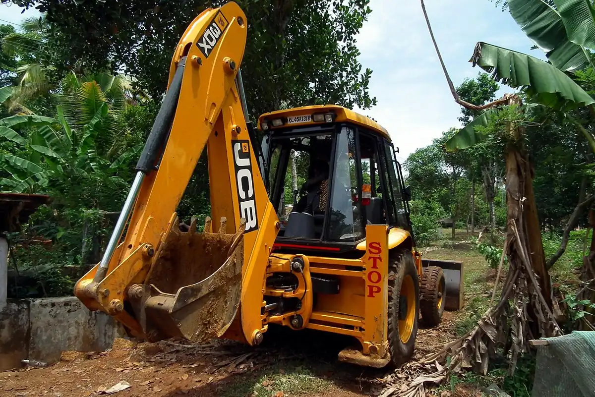
Concept
FK as a chain
FK is a function
Write the joint values as a list q = (q₁, q₂, …, qₙ). FK is a function T_B_tool = FK(q) that returns the tool pose in the base frame. For a normal (serial) arm there is exactly one answer for each q — you just multiply things out. That is why FK is easy and IK (pose → q) is hard.
Build it link by link
T_B_tool = [R(q₁) · Tr(L₁)] · [R(q₂) · Tr(L₂)] · … · [R(qₙ) · Tr(Lₙ)]

After each bracket, the last column of the running product is the next joint (or the tip).
Each bracket is one link: rotate by its joint angle, then go along its length. Multiply from the base outwards. Because every bracket is measured in the frame of the link before it, joint 2’s angle is automatically added to joint 1’s — exactly the θ₁ + θ₂ you saw in Lesson 1.
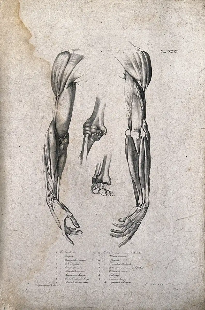
| Output | Used for |
|---|---|
| Tool pose (x, y, φ) or T_B_tool | Knowing where the tool is right now, from the encoders |
| Every joint position | Drawing the arm on screen; checking for collisions with the table or itself |
| A way to check IK | Plug the IK answer into FK; the error should be ~0 |
| The workspace | Run FK over many q to see all reachable points (Lesson 11) |
Visual
Visualise it: the FK chain
Slide the joints and read the tool pose and the planar T matrix. Every set of joint values gives exactly one pose.
Interactive · FK chain visualizer (3R planar educational)


Simplified 3R planar stand-in for Base→J1→J2→J3→EE. Full 6DOF adds wrist RPY on top of this position chain.
EE x
153.4
EE y
35.8
ᵇTₑ (planar) calculator
| 0.966 | -0.259 | 0.000 | 157.02 |
| 0.259 | 0.966 | 0.000 | 20.55 |
| 0.000 | 0.000 | 1.000 | 0.00 |
| 0.000 | 0.000 | 0.000 | 1.000 |
Code lab
Code lab: a general FK chain
fk_chain.py has one function, fk(lengths, joints_deg), that works for any number of links. It multiplies one ‘rotate, then go along the link’ per joint and records every joint position on the way. It uses the 3-link arm (10, 8, 4 cm) from Lesson 3.
# fk_chain.py - forward kinematics as a CHAIN of "rotate at the joint, then go along the link".
# Works for any number of links in a plane. It also returns where every joint is,
# which you need for drawing the arm or checking it does not hit something.
import math


def R(deg):
    c, s = math.cos(math.radians(deg)), math.sin(math.radians(deg))
    return [[c, -s, 0.0], [s, c, 0.0], [0.0, 0.0, 1.0]]


def Tr(x, y):
    return [[1.0, 0.0, x], [0.0, 1.0, y], [0.0, 0.0, 1.0]]


def mul(A, B):
    return [[sum(A[i][k] * B[k][j] for k in range(3)) for j in range(3)] for i in range(3)]


def fk(lengths, joints_deg):
    """Return T_base_tool and the (x, y) of every joint and of the tip."""
    T = [[1.0, 0.0, 0.0], [0.0, 1.0, 0.0], [0.0, 0.0, 1.0]]
    points = [(0.0, 0.0)]
    for L, q in zip(lengths, joints_deg):
        T = mul(mul(T, R(q)), Tr(L, 0.0))          # one link: rotate at the joint, go along it
        points.append((T[0][2], T[1][2]))
    return T, points


def pose(T):
    return T[0][2], T[1][2], math.degrees(math.atan2(T[1][0], T[0][0]))


LINKS = [10.0, 8.0, 4.0]                           # same 3-link arm as Lesson 3

print("1) Walk along the chain for joints (30°, 45°, -30°)")
T, pts = fk(LINKS, [30, 45, -30])
for name, p in zip(["base", "joint 2", "joint 3", "tool tip"], pts):
    print(f"   {name:<8} at ({p[0] + 0.0:6.2f}, {p[1] + 0.0:6.2f})")
x, y, phi = pose(T)
print(f"   tool pose (x, y, phi) = ({x:.2f}, {y:.2f}, {phi:.1f}°)")

print("\n2) Check against the closed-form formula (sum of link vectors)")
a1, a12, a123 = math.radians(30), math.radians(75), math.radians(45)
xc = 10 * math.cos(a1) + 8 * math.cos(a12) + 4 * math.cos(a123)
yc = 10 * math.sin(a1) + 8 * math.sin(a12) + 4 * math.sin(a123)
print(f"   formula gives ({xc:.2f}, {yc:.2f})  same answer: {math.dist((x, y), (xc, yc)) < 1e-9}")

print("\n3) FK has exactly one answer, and it is fast: a quick sweep of joint 1")
for q1 in (0, 30, 60, 90):
    x, y, phi = pose(fk(LINKS, [q1, 45, -30])[0])
    print(f"   q = ({q1:2d}°, 45°, -30°) -> ({x:6.2f}, {y:6.2f}, {phi:5.1f}°)")

print("\n4) FK as the judge of an IK answer (always check IK with FK)")
target = (14.0, 6.0)
guesses = {"from Lesson 3 IK": [-11.52, 100.08, -88.56], "a wrong guess": [-11.52, 90.0, -88.56]}
for name, q in guesses.items():
    x, y, _ = pose(fk(LINKS, q)[0])
    print(f"   {name:<17} -> tip ({x:6.2f}, {y:6.2f}), error {math.dist((x, y), target):.2f} cm")
Output (run with python3 fk_chain.py)
1) Walk along the chain for joints (30°, 45°, -30°)
   base     at (  0.00,   0.00)
   joint 2  at (  8.66,   5.00)
   joint 3  at ( 10.73,  12.73)
   tool tip at ( 13.56,  15.56)
   tool pose (x, y, phi) = (13.56, 15.56, 45.0°)

2) Check against the closed-form formula (sum of link vectors)
   formula gives (13.56, 15.56)  same answer: True

3) FK has exactly one answer, and it is fast: a quick sweep of joint 1
   q = ( 0°, 45°, -30°) -> ( 19.52,   6.69,  15.0°)
   q = (30°, 45°, -30°) -> ( 13.56,  15.56,  45.0°)
   q = (60°, 45°, -30°) -> (  3.96,  20.25,  75.0°)
   q = (90°, 45°, -30°) -> ( -6.69,  19.52, 105.0°)

4) FK as the judge of an IK answer (always check IK with FK)
   from Lesson 3 IK  -> tip ( 14.00,   6.00), error 0.00 cm
   a wrong guess     -> tip ( 15.33,   5.14), error 1.59 cm
Try it: slide θ₁–θ₃ and read the tip and the planar T matrix. Move only θ₁ and watch every link after it move.
Interactive · FK chain visualizer (3R planar educational)
Simplified 3R planar stand-in for Base→J1→J2→J3→EE. Full 6DOF adds wrist RPY on top of this position chain.
EE x
153.4
EE y
35.8
ᵇTₑ (planar) calculator
| 0.966 | -0.259 | 0.000 | 157.02 |
| 0.259 | 0.966 | 0.000 | 20.55 |
| 0.000 | 0.000 | 1.000 | 0.00 |
| 0.000 | 0.000 | 0.000 | 1.000 |
Simulator
Try it in the simulator
Simulator · Kinematics
2-link planar arm: forward & inverse kinematics
Move the joints (FK) or drag the target (IK) and compare the elbow-up and elbow-down solutions.
Loading simulator…
Formulas used
- x = L1·cos θ1 + L2·cos(θ1 + θ2)
- y = L1·sin θ1 + L2·sin(θ1 + θ2)
- cos θ2 = (x² + y² − L1² − L2²) / (2·L1·L2)
- θ1 = atan2(y, x) − atan2(L2·sin θ2, L1 + L2·cos θ2)
Model & limits
Ideal rigid links, point joints, no joint limits or collisions. Reachable only when |L1 − L2| ≤ r ≤ L1 + L2.
Real world
Forward kinematics in the real world
- Robot controllers: read the encoders, run FK, and show the tool position on the teach pendant — many times a second.
- Digital twins and simulators: draw the robot on screen by running FK for every link.
- Safety systems: check that no link enters a forbidden zone, using FK joint positions.
Bench build
Bench build: a two-servo arm that knows where its tip is
Mount one servo as the shoulder on a heavy base, glue a 10 cm card or ice-cream-stick link to its horn, and mount a second servo (the elbow) at the end, with an 8 cm link and a pointer. two_servo_fk.ino takes two angles from the Serial Monitor, moves both servos and prints the FK elbow and tip positions. Put graph paper underneath and compare the printed tip with the real one.
| From | To | Note |
|---|---|---|
| Both servos red (+) | Separate 5–6 V supply + (2 A or more) | NEVER the Arduino 5 V pin |
| Both servos brown/black (−) | Supply − AND Arduino GND | Grounds joined |
| Shoulder signal | Pin 5 | — |
| Elbow signal | Pin 6 | — |
Measure the links
Measure shaft-to-shaft (L1) and elbow shaft to pointer (L2). Type them into the sketch.
Find the zeros
Type
0 0. Adjust SH_ZERO and EL_ZERO until both links lie straight along the paper’s +x axis.Test FK
Type
30 45,0 60and-30 30. Mark the real tip each time and write the printed tip beside it.Measure the error
How far apart are printed and real? Which pose is worst, and why might that be (servo play, link bending, zero offset)?
// two_servo_fk.ino - a 2-link servo arm that reports its own tip position with forward kinematics.
// Type two angles, e.g. "30 60", in Serial Monitor. The servos move, and FK prints where the tip
// should be. Mark the real tip on graph paper and compare.
// SERVOS run from their OWN 5-6 V supply (2 A or more), NEVER from the Arduino 5 V pin.
// Join the servo supply GND to Arduino GND. Signal wires: shoulder -> pin 5, elbow -> pin 6.
#include <Servo.h>
const float L1 = 10.0, L2 = 8.0;                  // shaft-to-shaft and shaft-to-tip, in cm - MEASURE
const int SH_ZERO = 90, EL_ZERO = 90;             // servo command that gives 0 deg for each joint
Servo shoulder, elbow;

void setup() {
  shoulder.attach(5); elbow.attach(6);
  shoulder.write(SH_ZERO); elbow.write(EL_ZERO);
  Serial.begin(115200);
  Serial.println(F("Type: shoulder_deg elbow_deg   (each -70..70)"));
}

void loop() {
  if (!Serial.available()) return;
  float q1 = constrain(Serial.parseFloat(), -70, 70);   // stay inside safe servo travel
  float q2 = constrain(Serial.parseFloat(), -70, 70);
  while (Serial.available()) Serial.read();
  shoulder.write(SH_ZERO + (int)q1);
  elbow.write(EL_ZERO + (int)q2);
  // forward kinematics: rotate at joint 1, go L1; rotate at joint 2, go L2
  float a1 = radians(q1), a12 = radians(q1 + q2);
  float ex = L1 * cos(a1), ey = L1 * sin(a1);            // elbow position
  float tx = ex + L2 * cos(a12), ty = ey + L2 * sin(a12); // tip position
  Serial.print(F("q = (")); Serial.print(q1, 0); Serial.print(F(", ")); Serial.print(q2, 0);
  Serial.print(F(")  elbow (")); Serial.print(ex, 1); Serial.print(F(", ")); Serial.print(ey, 1);
  Serial.print(F(")  tip (")); Serial.print(tx, 1); Serial.print(F(", ")); Serial.print(ty, 1);
  Serial.println(F(")"));
}
Debugging
Debugging FK
| Symptom | Likely cause | Fix |
|---|---|---|
| Tip right only when joint 1 is 0° | Link angles not summed (θ₂ used instead of θ₁ + θ₂) | Chain transforms, or sum the angles |
| Tip mirrored | Joint angle sign flipped (servo turns the other way) | Negate that joint in the code |
| Constant offset at every pose | Wrong link length | Measure shaft-centre to shaft-centre |
| Error depends on the pose | Joint zero wrong | Re-set SH_ZERO / EL_ZERO with the links straight |
| Small random errors (a few mm) | Servo backlash or bending links | Stiffer links; approach each pose from the same side |
| Arduino resets when servos move | Servos on Arduino power | Separate supply, joined grounds |
Think
Think about it
Think
Your two-servo arm prints a tip that is always about 4 mm off, in a direction that changes with the pose. You measured L1 and L2 very carefully. What is the most likely cause, and how would you test it?
Experiment
Try it in the lab
About 35 minutes with the Python file, the FK visualiser and (optionally) the two-servo arm.
Experiment
FK by hand, by code and by servo
You will need
- `fk_chain.py` and Python 3
- FK chain visualiser (in your browser)
- Graph paper, ruler, protractor
- Optional: Arduino UNO, two micro servos, separate 5–6 V supply, card links, jumper wires
Steps
- Compute FK for (30°, 45°, −30°) by hand with the link-vector sum. Check against Part 1.
- Change `LINKS` to a 4-link arm (10, 8, 6, 3) and add a fourth angle. The function needs no other changes — why?
- In Part 4, change the wrong guess by 1° instead of 10°. How big is the error now?
- Use FK in a loop: print the tip for q₂ from −90° to 90° in 30° steps (q₁ = 0, q₃ = 0) and sketch the path.
- In the FK visualiser, find two different joint settings that put the tip at almost the same place. What does that tell you about IK?
- Optional: test three poses on the two-servo arm and record the error.
Interactive · FK chain visualizer (3R planar educational)
Simplified 3R planar stand-in for Base→J1→J2→J3→EE. Full 6DOF adds wrist RPY on top of this position chain.
EE x
153.4
EE y
35.8
ᵇTₑ (planar) calculator
| 0.966 | -0.259 | 0.000 | 157.02 |
| 0.259 | 0.966 | 0.000 | 20.55 |
| 0.000 | 0.000 | 1.000 | 0.00 |
| 0.000 | 0.000 | 0.000 | 1.000 |
FK always gives one answer and works for any number of links with the same loop. Small joint errors give tip errors that grow with reach. Different q can give the same tip — FK is many-to-one, which is why IK can have several answers.
Knowledge check
Check your understanding
Knowledge check
1. Forward kinematics answers…
2. For a normal serial arm, how many FK answers does one set of joint values have?
3. One link in the planar FK chain is…
4. In fk_chain.py Part 1, the tool points at 45°. Where does that come from?
5. Why should you always check an IK answer with FK?
6. Your FK tip is right only when joint 1 is at 0°. The bug is probably…
7. Two servos make your Arduino reset when they move. The fix is…
Mini assignment
Hands-on assignment
Mini assignment
FK worksheet for a real arm
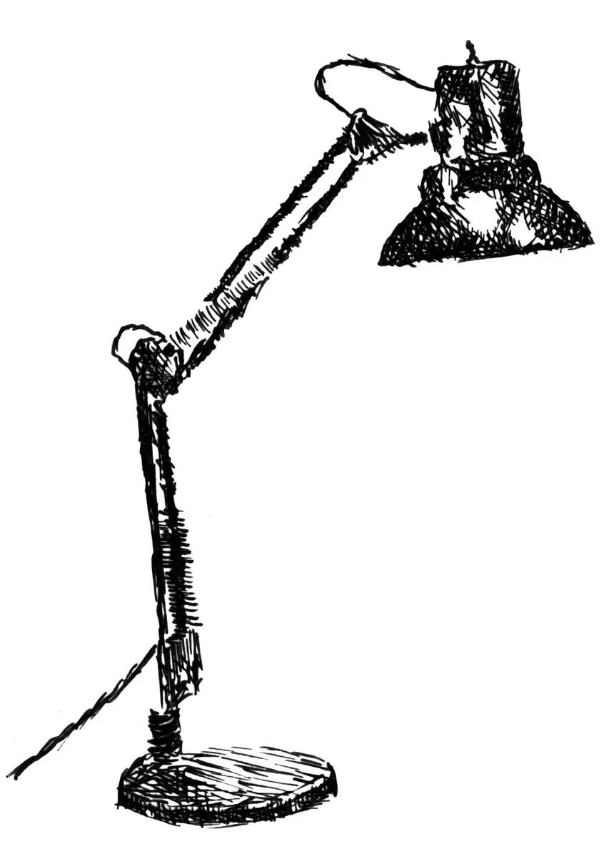
Write and test FK for a 2- or 3-link arm you can measure: the two-servo arm, a desk lamp or your Stage 6 arm’s planar view.
Deliverables
- A labelled sketch: links L1…Ln, joint angles, base frame.
- The FK chain written as a product of R(q) · Tr(L) brackets.
- `fk_chain.py` run for three poses, with every joint position listed.
- The same three poses measured on the real arm, and a table of errors.
- Two sentences on where the errors come from (zeros, lengths, play).
Do this, step by step
- Choose your arm: the two-servo arm, a desk lamp or the planar view of your Stage 6 arm. Measure each link from joint axis to joint axis.
- Put your lengths in
LINKSinfk_chain.pyand run it for three poses. Copy every joint position, not only the tip. - Set the real arm (or lamp) to the same three poses using a protractor, and measure the tip with a ruler.
- Make an error table: predicted tip, measured tip, difference. Circle the worst pose.
- In the FK chain visualiser, set the same angles and check the drawing matches your real arm’s shape.
Stuck? Hints, one at a time
- Measure lengths from joint axis to joint axis, not along the outside of the parts.
- If the errors are the same size in every pose, suspect a zero offset; if they grow with reach, suspect a length.
- Write each joint’s 0° and positive direction on the arm with tape before you measure.
Challenges (pick by level)
- 🟢 Easy: FK by hand for a 2-link arm (10, 8) at (90°, −90°).
- 🟢 Easy: Add a fourth link to
LINKSand run Part 1. - 🟡 Medium: Make
fk_chain.pyprint an ASCII drawing or save a CSV of joint positions you can plot. - 🟠 Hard-ish: Add a prismatic (sliding) joint: a link whose length is a joint variable. Change
fk()to support it. - 🔴 Hard: Use FK to find, by brute force, a set of three joint angles that puts the tip within 0.1 cm of (5, 15) with φ = 90°.
- ⚫ Research: Find how a 6-joint industrial arm’s FK is written (one 4 × 4 transform per joint) in a robotics textbook or the Modern Robotics book.
Next step
In Lesson 7 — Forward Kinematics: 6DOF Arm you take the same idea into 3D and apply it to the arm you built in Stage 6.
Look back: Lesson 5: Rotation & Translation. Next: Lesson 7: Forward Kinematics — 6DOF Arm. Related: Stage 1: Math → Robot Connection and Stage 6 — 6DOF Arm.
Sources
- Wikipedia — Forward kinematics — FK uses the kinematic equations to compute the end-effector position from joint parameters; the reverse is inverse kinematics.
- Wikipedia — Robot kinematics — for serial manipulators, FK is direct substitution of the joint parameters into the chain equations.
- Modern Robotics — K. M. Lynch & F. C. Park (book home page, free preprint) — chapters on Rigid-Body Motions and Forward Kinematics (FK of open chains from homogeneous transforms).
- Photos and drawings: Wikimedia Commons (credits under each image).
Self-attested for now — keep artifacts in your lab notebook.
Complete
Today's goal
0 of 1 done today
Mark this lesson complete when you have worked the experiment, knowledge check, and assignment (even roughly).