
Kinematics & Inverse Kinematics · Lesson 04
Homogeneous Transformation Matrices
Est. 50–70 min
Why
Why this lesson matters
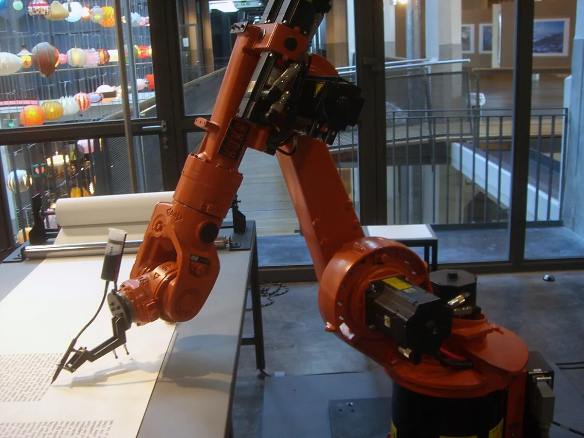
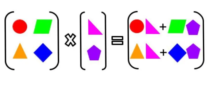
In Lessons 2–3 you moved points with two separate pieces: a rotation R and an offset p. That works, but it gets messy when you chain five or six frames — rotate, add, rotate, add… A homogeneous transformation matrix T packs R and p into one 4 × 4 matrix, so moving through a whole chain of frames becomes just multiplying matrices. Forward kinematics for every robot arm in this stage is built from these matrices.
By the end of this lesson you will be able to: write T = [R p; 0 0 0 1] and read its parts; apply T to a point using the extra ‘1’; chain transforms with T_A_C = T_A_B · T_B_C; explain why the order matters; invert a transform with Rᵀ and −Rᵀp; and chain transforms on a servo-driven distance sensor.
Concept
One matrix for rotation and translation
The 4 × 4 matrix
        [ r11 r12 r13 | px ]
T_A_B = [ r21 r22 r23 | py ]     R = 3×3 rotation (Lesson 3)
        [ r31 r32 r33 | pz ]     p = where {B}’s origin is, in {A}
        [  0   0   0  |  1 ]     bottom row is always 0 0 0 1
Read T_A_B as “frame {B} as seen from frame {A}” (some books write ᴬT_B). Its first three columns are {B}’s x, y and z axes written in {A} (that is R), and its last column is {B}’s origin in {A} (that is p).
Why the extra 1?
To apply T to a point, write the point with a 1 on the end: [x, y, z, 1]. When you multiply, the 1 picks up the last column, so the result is R·p_B + p — rotation *and* translation in one step. These 4-number points are called homogeneous coordinates. A *direction* (like an axis) is written with a 0 on the end instead, so it rotates but does not move.
[p_A; 1] = T_A_B · [p_B; 1]          (move a point from {B} into {A})
T_A_C    = T_A_B · T_B_C            (chain: the inner letters cancel)
T_B_A    = (T_A_B)⁻¹ = [ Rᵀ  −Rᵀp ; 0 0 0 1 ]
The chain rule is easy to remember: in T_A_B · T_B_C the two inner B’s ‘cancel’ and leave T_A_C. If your inner letters do not match, the multiplication is wrong. The inverse of a rigid transform is cheap: transpose R and compute −Rᵀp — no general matrix inverse needed.
Visual
Visualise it: the transformation matrix lab
Edit T₁ and T₂ and inspect the composed matrix. The top-left 3 × 3 block is R; the last column is p; the bottom row stays 0 0 0 1.
Interactive · Transformation-matrix lab


Composed ᵖTᶜ = T₁·T₂ (planar teaching model, z fixed):
| 0.985 | -0.174 | 0.000 | 58.74 |
| 0.174 | 0.985 | 0.000 | 40.80 |
| 0.000 | 0.000 | 1.000 | 0.00 |
| 0.000 | 0.000 | 0.000 | 1.000 |
R block | p column · bottom [0 0 0 1]
Code lab
Code lab: a camera on the wrist
transforms.py builds 4 × 4 matrices with plain Python lists. The robot’s flange {F} is at (20, 5, 30) cm in the base {B}, turned 90°. A camera {C} is bolted 3 cm along the flange’s x axis and 2 cm below it. The camera sees a cup; the code chains the transforms to find the cup in the base frame, shows the wrong order, and goes back with the inverse.
# transforms.py - homogeneous transformation matrices with plain Python lists (no numpy needed).
# T = [[R, p], [0 0 0 1]] says how a CHILD frame sits inside a PARENT frame.
# Apply to a point: [p_parent; 1] = T @ [p_child; 1].   Chain: T_a_c = T_a_b @ T_b_c.
import math


def T_from(yaw_deg=0.0, p=(0.0, 0.0, 0.0)):
    """4x4 transform: rotate yaw_deg about z, then translate by p (cm)."""
    c, s = math.cos(math.radians(yaw_deg)), math.sin(math.radians(yaw_deg))
    return [[c, -s, 0.0, p[0]],
            [s, c, 0.0, p[1]],
            [0.0, 0.0, 1.0, p[2]],
            [0.0, 0.0, 0.0, 1.0]]


def mul(A, B):
    return [[sum(A[i][k] * B[k][j] for k in range(4)) for j in range(4)] for i in range(4)]


def apply(T, p):
    v = (p[0], p[1], p[2], 1.0)                       # the extra 1 lets translation happen
    return tuple(sum(T[i][k] * v[k] for k in range(4)) for i in range(3))


def inv(T):
    """Inverse of a rigid transform: R^T and -R^T p (no general matrix inverse needed)."""
    R = [[T[j][i] for j in range(3)] for i in range(3)]          # transpose of the 3x3 block
    p = [T[i][3] for i in range(3)]
    q = [-sum(R[i][k] * p[k] for k in range(3)) for i in range(3)]
    return [R[0] + [q[0]], R[1] + [q[1]], R[2] + [q[2]], [0.0, 0.0, 0.0, 1.0]]


def show(name, T):
    print(f"   {name}")
    for row in T:
        print("     [" + " ".join(f"{v + 0.0:7.2f}" for v in row) + " ]")


# A robot on a table. Flange {F} in base {B}: 20 cm forward, 5 cm left, 30 cm up, turned 90 deg.
T_B_F = T_from(90, (20.0, 5.0, 30.0))
# A camera {C} bolted to the flange: 3 cm along the flange's x, 2 cm down, not turned.
T_F_C = T_from(0, (3.0, 0.0, -2.0))

print("1) Two transforms and their chain T_B_C = T_B_F @ T_F_C")
show("T_B_F (flange in base)", T_B_F)
show("T_F_C (camera in flange)", T_F_C)
T_B_C = mul(T_B_F, T_F_C)
show("T_B_C (camera in base)", T_B_C)

cup_C = (10.0, 0.0, -25.0)                             # the camera sees a cup here
cup_B = apply(T_B_C, cup_C)
print(f"\n2) Cup seen by the camera at {cup_C} -> in base: ({cup_B[0]:.2f}, {cup_B[1]:.2f}, {cup_B[2]:.2f})")

print("\n3) Order matters: T_F_C @ T_B_F is a different matrix")
wrong = apply(mul(T_F_C, T_B_F), cup_C)
print(f"   wrong order puts the cup at ({wrong[0]:.2f}, {wrong[1]:.2f}, {wrong[2]:.2f})"
      f" - {math.dist(cup_B, wrong):.2f} cm away from the truth")

print("\n4) Going back: the inverse transform")
T_C_B = inv(T_B_C)
back = apply(T_C_B, cup_B)
print(f"   cup back in camera frame: ({back[0]:.2f}, {back[1]:.2f}, {back[2]:.2f})")
I = mul(T_B_C, T_C_B)
err = max(abs(I[i][j] - (1.0 if i == j else 0.0)) for i in range(4) for j in range(4))
print(f"   T_B_C @ T_C_B is the identity matrix: {err < 1e-12}  (largest error below 1e-12)")
Output (run with python3 transforms.py)
1) Two transforms and their chain T_B_C = T_B_F @ T_F_C
   T_B_F (flange in base)
     [   0.00   -1.00    0.00   20.00 ]
     [   1.00    0.00    0.00    5.00 ]
     [   0.00    0.00    1.00   30.00 ]
     [   0.00    0.00    0.00    1.00 ]
   T_F_C (camera in flange)
     [   1.00    0.00    0.00    3.00 ]
     [   0.00    1.00    0.00    0.00 ]
     [   0.00    0.00    1.00   -2.00 ]
     [   0.00    0.00    0.00    1.00 ]
   T_B_C (camera in base)
     [   0.00   -1.00    0.00   20.00 ]
     [   1.00    0.00    0.00    8.00 ]
     [   0.00    0.00    1.00   28.00 ]
     [   0.00    0.00    0.00    1.00 ]

2) Cup seen by the camera at (10.0, 0.0, -25.0) -> in base: (20.00, 18.00, 3.00)

3) Order matters: T_F_C @ T_B_F is a different matrix
   wrong order puts the cup at (23.00, 15.00, 3.00) - 4.24 cm away from the truth

4) Going back: the inverse transform
   cup back in camera frame: (10.00, 0.00, -25.00)
T_B_C @ T_C_B is the identity matrix: True (largest error below 1e-12)Try it: set T₁ and T₂, then read the composed matrix. Find the R block and the p column, and swap the order to see the result change.
Interactive · Transformation-matrix lab
Composed ᵖTᶜ = T₁·T₂ (planar teaching model, z fixed):
| 0.985 | -0.174 | 0.000 | 58.74 |
| 0.174 | 0.985 | 0.000 | 40.80 |
| 0.000 | 0.000 | 1.000 | 0.00 |
| 0.000 | 0.000 | 0.000 | 1.000 |
R block | p column · bottom [0 0 0 1]
Real world
Transforms in the real world
- Forward kinematics: every arm’s FK is a product of one transform per joint and link — you will build it in Lessons 6–7.
- ROS: robot software keeps a tree of frames and multiplies these transforms (often stored as a quaternion plus a vector) to move data between them.
- Camera calibration: a ‘hand–eye’ calibration finds the camera-to-flange transform once, so every image point can be chained into the base frame.
- 3D graphics and games: every object on screen is drawn with 4 × 4 matrices in homogeneous coordinates — the same maths.
Bench build
Bench build: a pan scanner that chains transforms
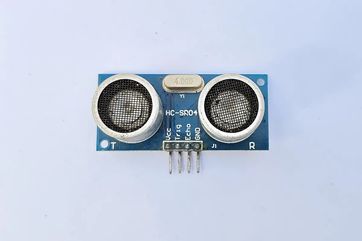
Mount the HC-SR04 sensor from Lesson 2 on a hobby servo horn so it can turn. Now there are three frames: base {B}, the pan axis {P} (fixed on the table) and the sensor {S} (turns with the servo, 2 cm in front of the axis). pan_scanner.ino sweeps the servo from 30° to 150° and, at each angle, chains T_B_P · Rz(angle) · T_offset to print where the echo came from in the base frame. Plot the points and you get a top-view map of objects on the table.
| From | To | Note |
|---|---|---|
| Servo red (+) | Separate 5–6 V supply + (4 × AA or a 5 V adapter) | NEVER the Arduino 5 V pin |
| Servo brown/black (−) | Supply − AND Arduino GND | Grounds must be joined |
| Servo orange/yellow (signal) | Arduino pin 6 | Signal only |
| HC-SR04 VCC / GND | Arduino 5 V / GND | Sensor only — small current |
| HC-SR04 TRIG / ECHO | Pins 9 / 10 | — |
Mount
Hot-glue or tape the sensor on the servo horn, facing outwards. Fix the servo to a block so it cannot tip over.
Measure the frames
Measure where the servo axis is in your base frame (PAN_X, PAN_Y) and which way ‘servo 90°’ faces (PAN_YAW). Measure the sensor’s distance from the axis (SENSOR_OFFSET).
Upload and sweep
Open Serial Monitor at 115200. Place two boxes in front of the scanner.
Plot
Copy the x_B, y_B columns into a spreadsheet and draw a scatter plot. Do the points line up with the box faces?
Break one transform
Set PAN_YAW 20° wrong. The whole map turns — the error grows with distance, just like Lesson 2.
// pan_scanner.ino - chain two transforms on real hardware.
// A hobby servo turns an HC-SR04 distance sensor. Three frames:
//   {B} base (your table), {P} pan servo axis (fixed in {B}), {S} sensor (turns with the servo).
//   T_B_S = T_B_P * Rz(servo angle) * T_offset ;  point_B = T_B_S * [d, 0, 0, 1]
// The SERVO is powered from its OWN 5-6 V supply (4 x AA or a 5 V adapter), NEVER from the Arduino
// 5 V pin. Join the servo supply GND to Arduino GND. Only the signal wire goes to pin 6.
// HC-SR04: VCC -> 5 V, GND -> GND, TRIG -> 9, ECHO -> 10.
#include <Servo.h>
const int TRIG = 9, ECHO = 10, SERVO_PIN = 6;
const float PAN_X = 30.0, PAN_Y = 0.0, PAN_YAW = 90.0;   // servo axis in {B} (cm, deg) - MEASURE YOURS
const float SENSOR_OFFSET = 2.0;                        // sensor face is 2 cm in front of the axis
Servo pan;

// A 2D homogeneous transform (3x3) is enough on a flat table: [c -s x; s c y; 0 0 1]
struct T2 { float m[3][3]; };
T2 make(float yawDeg, float x, float y) {
  float c = cos(radians(yawDeg)), s = sin(radians(yawDeg));
  T2 t = {{{c, -s, x}, {s, c, y}, {0, 0, 1}}};
  return t;
}
T2 mul(const T2 &a, const T2 &b) {
  T2 r;
  for (int i = 0; i < 3; i++)
    for (int j = 0; j < 3; j++) {
      r.m[i][j] = 0;
      for (int k = 0; k < 3; k++) r.m[i][j] += a.m[i][k] * b.m[k][j];
    }
  return r;
}

float readCm() {
  digitalWrite(TRIG, LOW); delayMicroseconds(2);
  digitalWrite(TRIG, HIGH); delayMicroseconds(10);
  digitalWrite(TRIG, LOW);
  unsigned long us = pulseIn(ECHO, HIGH, 30000UL);
  return us == 0 ? -1 : us * 0.0343 / 2.0;
}

void setup() {
  pinMode(TRIG, OUTPUT); pinMode(ECHO, INPUT);
  pan.attach(SERVO_PIN);
  Serial.begin(115200);
  Serial.println(F("servo_deg, d_cm, x_B, y_B"));
}

void loop() {
  for (int a = 30; a <= 150; a += 10) {                 // stay away from the servo's end stops
    pan.write(a);
    delay(300);                                         // let the servo arrive and stop shaking
    float d = readCm();
    if (d < 0) continue;
    // servo 90 = straight ahead of the pan frame, so the turn is (a - 90) degrees
    T2 tBS = mul(mul(make(PAN_YAW, PAN_X, PAN_Y), make(a - 90, 0, 0)), make(0, SENSOR_OFFSET, 0));
    float xb = tBS.m[0][0] * d + tBS.m[0][2];           // T * [d, 0, 1]
    float yb = tBS.m[1][0] * d + tBS.m[1][2];
    Serial.print(a); Serial.print(F(", ")); Serial.print(d, 1); Serial.print(F(", "));
    Serial.print(xb, 1); Serial.print(F(", ")); Serial.println(yb, 1);
  }
  Serial.println(F("# sweep done"));
  delay(2000);
}
Debugging
Debugging transforms
| Symptom | Likely cause | Fix |
|---|---|---|
| Point lands in a believable but wrong place | Multiplied in the wrong order | Check the inner letters match: T_A_B · T_B_C |
| Translation has no effect | Point written with a 0 instead of a 1 at the end | Points end with 1; directions end with 0 |
| Inverse gives nonsense | Used −p instead of −Rᵀp | Inverse is [Rᵀ, −Rᵀp] |
| Bottom row is not 0 0 0 1 | Typing mistake or bad multiplication | Rebuild T from R and p |
| Scanner map is turned | PAN_YAW wrong | Re-measure which way servo 90° faces |
| Scanner map is shifted | PAN_X / PAN_Y wrong | Re-measure the axis position |
| Arduino resets when the servo moves | Servo powered from the Arduino | Use a separate servo supply, join grounds |
Think
Think about it
Think
The camera is bolted to the flange, so T_F_C never changes. When the arm moves, which matrix in T_B_C = T_B_F · T_F_C changes, and where does it come from?
Experiment
Try it in the lab
About 35 minutes with the Python file, the transform lab and (optionally) the pan scanner.
Experiment
Chain, swap and invert
You will need
- `transforms.py` and Python 3
- Transformation matrix lab (in your browser)
- Optional: Arduino UNO, SG90 or similar servo, separate 5–6 V supply, HC-SR04, jumper wires
Steps
- Run `transforms.py`. Check one entry of T_B_C by hand: row 2 of T_B_F times column 4 of T_F_C.
- Change the flange yaw from 90° to 0°. Predict the cup’s base-frame position before running.
- Add a tool frame {T} 6 cm below the camera and print T_B_T = T_B_F · T_F_C · T_C_T.
- Apply T_B_C to the direction (1, 0, 0, **0**) instead of a point. What changes compared with (1, 0, 0, 1)?
- In the transform lab, find two transforms where swapping the order makes no difference. What do they have in common?
- Optional: run the pan scanner and plot one sweep.
Interactive · Transformation-matrix lab
Composed ᵖTᶜ = T₁·T₂ (planar teaching model, z fixed):
| 0.985 | -0.174 | 0.000 | 58.74 |
| 0.174 | 0.985 | 0.000 | 40.80 |
| 0.000 | 0.000 | 1.000 | 0.00 |
| 0.000 | 0.000 | 0.000 | 1.000 |
R block | p column · bottom [0 0 0 1]
Chaining is one multiplication per frame. Order matters except in special cases (for example two pure translations, or two rotations about the same axis). A direction with a 0 ignores the translation column.
Knowledge check
Check your understanding
Knowledge check
1. A homogeneous transform for 3D is…
2. In T_A_B, the last column (top three numbers) is…
3. Which product gives T_A_C?
4. Why do points get a 1 as their 4th number?
5. The inverse of T = [R p; 0 0 0 1] is…
6. In transforms.py, where is the cup in the base frame?
7. Your Arduino resets every time the pan servo moves. The fix is…
Mini assignment
Hands-on assignment
Mini assignment
Transform chain for your desk
Write the transform chain from your robot base to a tool and a camera, and check it with code.
Deliverables
- A sketch with {B}, {F}, {T} and {C}, and each transform labelled (T_B_F, T_F_T, T_F_C).
- Each 4 × 4 matrix written out, with R and p marked.
- T_B_T and T_B_C computed with `transforms.py`, and one entry checked by hand.
- A point seen by the camera converted into the base frame, and back again with the inverse.
- Optional: one pan-scanner sweep plotted, with the box positions marked.
Do this, step by step
- Run
python3 transforms.pyand copy T_B_F, T_F_C and T_B_C. Mark R (top-left 3 × 3) and p (last column) on each. - Check one entry of T_B_C by hand: rotate the camera offset (3, 0, −2) by 90° about z and add (20, 5, 30).
- Measure a real flange-to-camera offset on your arm (or invent one with a ruler) and change T_F_C. Run again.
- Take a point the camera ‘sees’, convert it to the base with T_B_C, then back with T_C_B. The round trip must give the same numbers.
- Use the transformation matrix lab to rebuild one of your matrices and compare the drawn frame with your sketch.
Stuck? Hints, one at a time
- R is the top-left 3 × 3 block; p is the first three numbers of the last column.
- To go from camera to base, multiply by T_B_C; to go back, use its inverse, not its transpose.
- The bottom row must always be 0 0 0 1. If it is not, a multiplication went wrong.
Challenges (pick by level)
- 🟢 Easy: Write T for ‘move 10 cm along x, no rotation’ and apply it to (1, 2, 3).
- 🟢 Easy: Write T for ‘turn 90° about z, no move’ and apply it to (1, 0, 0).
- 🟡 Medium: Show with code that two translations commute but a rotation and a translation do not.
- 🟠 Hard-ish: Add
rx()andry()versions ofT_from()and build a camera that looks straight down. - 🔴 Hard: Write
chain(list_of_T)and use it to compute the tip of the 2-link arm from Lesson 1 as T(θ₁)·T(L1)·T(θ₂)·T(L2). Compare with the Lesson 1 formula. - ⚫ Research: Find out how a quaternion plus a vector stores the same information as T, and why software often prefers it.
Next step
In Lesson 5 — Rotation & Translation you will take T apart again: which part rotates, which part moves, and why ‘rotate then move’ is not ‘move then rotate’.
Look back: Lesson 3: Position, Orientation & Pose. Next: Lesson 5: Rotation & Translation. Related: Stage 1: Homogeneous Transformation and Stage 1: Matrices.
Sources
- Wikipedia — Transformation matrix — affine transformations and why homogeneous coordinates let translation be written as a matrix product.
- Wikipedia — Homogeneous coordinates — the extra coordinate used in projective geometry and computer graphics.
- Modern Robotics — K. M. Lynch & F. C. Park (book home page, free preprint) — Chapter 3, Rigid-Body Motions: homogeneous transformation matrices, their inverse and composition.
- Wikipedia — Rotation matrix — Rᵀ = R⁻¹ for a rotation, used in the cheap inverse.
- Photos and diagram: Wikimedia Commons (credits under each image).
Self-attested for now — keep artifacts in your lab notebook.
Complete
Today's goal
0 of 1 done today
Mark this lesson complete when you have worked the experiment, knowledge check, and assignment (even roughly).