
Kinematics & Inverse Kinematics · Lesson 03
Position, Orientation & Pose
Est. 45–60 min
Why
Why this lesson matters
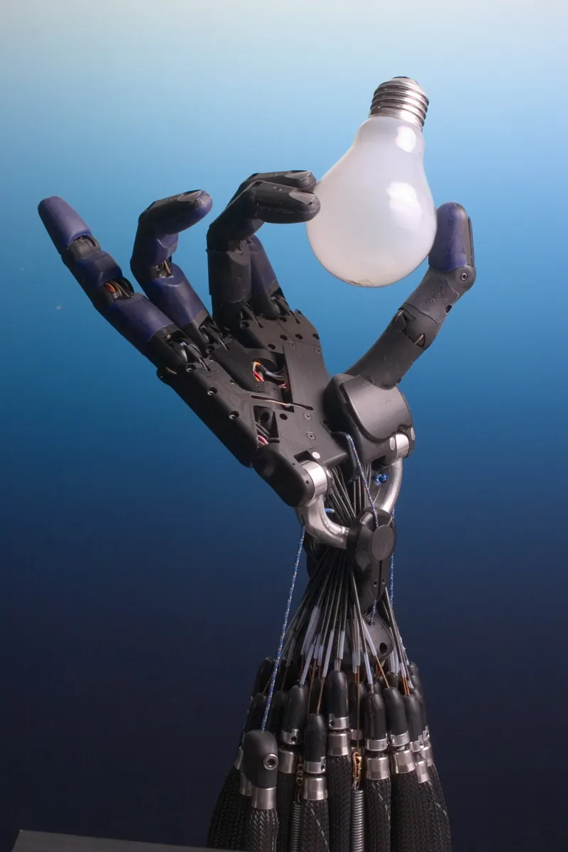
In Lessons 1–2 you described *where* a point is, in a named frame. But a tool is not a point. A pen, a gripper or a screwdriver also has a direction. Kinematics describes both: the position of the tool frame’s origin and the orientation of its axes. Together they are the tool’s pose.
By the end of this lesson you will be able to: separate position and orientation; describe a planar pose as (x, y, φ); describe a 3D orientation with roll, pitch and yaw or with a rotation matrix R; check that a matrix really is a rotation (unit, perpendicular columns, det = +1); reach the same point with different tool angles using a 3-link arm; and measure roll and pitch with an MPU-6050 sensor.
Concept
Position, orientation and pose
Three words
| Word | Answers | In 2D (top view) | In 3D |
|---|---|---|---|
| Position p | Where is the tool frame’s origin? | (x, y) — 2 numbers | (x, y, z) — 3 numbers |
| Orientation R | Which way do its axes point? | one angle φ | 3 independent numbers (e.g. roll, pitch, yaw), often stored as a 3 × 3 matrix R |
| Pose (p, R) | Both together | (x, y, φ) — 3 numbers | 6 numbers — this is why a general-purpose arm has 6 joints |
A pose is always the pose of one frame in another frame, like “the tool frame {T} in the base frame {B}”. The position is where {T}’s origin is, measured in {B}; the orientation is how {T}’s axes are turned compared with {B}’s axes.
Orientation in 3D: roll, pitch, yaw
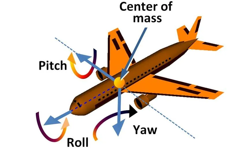
A common way to describe orientation is three turns: roll about the forward (x) axis, pitch about the side (y) axis and yaw about the vertical (z) axis. Pilots use the same words for an aeroplane. They are easy to imagine, but the order of the turns matters — roll then yaw is not the same as yaw then roll.
Orientation as a rotation matrix R
Robots usually store orientation as a 3 × 3 rotation matrix. Its trick is simple: each column is one of the tool’s axes, written in the base frame. Column 1 is where the tool’s x axis points, column 2 its y axis, column 3 its z axis. A real rotation matrix must pass three checks:
- Every column has length 1 (axes are unit length).
- Every pair of columns is at right angles (dot product 0).
- The determinant is +1 (a right-handed frame; −1 would be a mirror image).
Visual
Visualise it: position and yaw together
Position is where the tool frame’s origin is; orientation is which way its axes point. Change one at a time and read the full planar pose (x, y, yaw).
Interactive · Coordinate-frame explorer

Code lab
Code lab: same place, different pose
pose.py uses a 3-link planar arm: the 2-link arm from Lesson 1 plus a 4 cm tool. Its tool pose is (x, y, φ), where φ = θ₁ + θ₂ + θ₃ is the direction the tool points. ik3() walks back 4 cm along the tool to find the wrist, then reuses the 2-link IK. Part 3 builds a 3D rotation matrix and runs the three checks.
# pose.py - position + orientation = pose.
# Part 1-2: a 3-link planar arm (top view). Its tool pose is (x, y, phi): where the tip is AND
#           which way the tool points. The same tip position can have different tool angles.
# Part 3:   a 3D orientation as a rotation matrix R, and the checks every real R must pass.
import math

L1, L2, L3 = 10.0, 8.0, 4.0     # cm; link 3 is the tool (e.g. a pen or a small gripper)


def fk3(t1, t2, t3):
    """Joint angles in degrees -> tool pose (x, y, phi_deg)."""
    a1, a12, a123 = map(math.radians, (t1, t1 + t2, t1 + t2 + t3))
    x = L1 * math.cos(a1) + L2 * math.cos(a12) + L3 * math.cos(a123)
    y = L1 * math.sin(a1) + L2 * math.sin(a12) + L3 * math.sin(a123)
    return x, y, t1 + t2 + t3


def ik3(x, y, phi_deg, elbow=+1):
    """Tool pose -> joint angles. Step back along the tool to the wrist, then 2-link IK."""
    phi = math.radians(phi_deg)
    wx, wy = x - L3 * math.cos(phi), y - L3 * math.sin(phi)
    c2 = (wx * wx + wy * wy - L1 * L1 - L2 * L2) / (2 * L1 * L2)
    if abs(c2) > 1:
        return None
    t2 = elbow * math.acos(c2)
    t1 = math.atan2(wy, wx) - math.atan2(L2 * math.sin(t2), L1 + L2 * math.cos(t2))
    t1d, t2d = math.degrees(t1), math.degrees(t2)
    return t1d, t2d, phi_deg - t1d - t2d


print("1) Same tip position (14, 6), three different tool angles")
for phi in (0.0, 45.0, 90.0):
    q = ik3(14.0, 6.0, phi)
    x, y, p = fk3(*q)
    print(f"   phi {phi:5.1f}° -> joints ({q[0]:7.2f}°, {q[1]:7.2f}°, {q[2]:7.2f}°)"
          f"  check: x {x:5.2f}, y {y:5.2f}, phi {p:5.1f}°")

print("\n2) Position only is not enough: the tool direction (unit vector) for each phi")
for phi in (0.0, 45.0, 90.0):
    print(f"   phi {phi:5.1f}° -> tool points along ({math.cos(math.radians(phi)):5.2f},"
          f" {math.sin(math.radians(phi)):5.2f})")


def rz(deg):
    c, s = math.cos(math.radians(deg)), math.sin(math.radians(deg))
    return [[c, -s, 0.0], [s, c, 0.0], [0.0, 0.0, 1.0]]


def ry(deg):
    c, s = math.cos(math.radians(deg)), math.sin(math.radians(deg))
    return [[c, 0.0, s], [0.0, 1.0, 0.0], [-s, 0.0, c]]


def matmul(a, b):
    return [[sum(a[i][k] * b[k][j] for k in range(3)) for j in range(3)] for i in range(3)]


def det(m):
    return (m[0][0] * (m[1][1] * m[2][2] - m[1][2] * m[2][1])
            - m[0][1] * (m[1][0] * m[2][2] - m[1][2] * m[2][0])
            + m[0][2] * (m[1][0] * m[2][1] - m[1][1] * m[2][0]))


print("\n3) A 3D orientation: yaw 30° about z, then pitch 90° about the new y")
R = matmul(rz(30), ry(90))
for row in R:
    print("   [" + "  ".join(f"{v:6.3f}" for v in row) + " ]")
cols = [[R[i][j] for i in range(3)] for j in range(3)]
lengths = [math.sqrt(sum(v * v for v in c)) for c in cols]
dot01 = sum(cols[0][i] * cols[1][i] for i in range(3))
print(f"   column lengths {lengths[0]:.3f} {lengths[1]:.3f} {lengths[2]:.3f}  (each must be 1)")
print(f"   x·y = {abs(dot01):.3f}  (axes at right angles -> 0)   det(R) = {det(R):.3f}  (right-handed -> +1)")
for name, c in zip("xyz", cols):
    print(f"   tool {name} axis (column {'xyz'.index(name) + 1}) points along ({c[0]:6.3f}, {c[1]:6.3f}, {c[2]:6.3f})")
print("   -> the tool's x axis points straight down; its z axis lies flat, 30° round from base x")
Output (run with python3 pose.py)
1) Same tip position (14, 6), three different tool angles
   phi   0.0° -> joints ( -11.52°,  100.08°,  -88.56°)  check: x 14.00, y  6.00, phi   0.0°
   phi  45.0° -> joints ( -26.79°,  100.49°,  -28.70°)  check: x 14.00, y  6.00, phi  45.0°
   phi  90.0° -> joints ( -25.32°,   77.00°,   38.32°)  check: x 14.00, y  6.00, phi  90.0°

2) Position only is not enough: the tool direction (unit vector) for each phi
   phi   0.0° -> tool points along ( 1.00,  0.00)
   phi  45.0° -> tool points along ( 0.71,  0.71)
   phi  90.0° -> tool points along ( 0.00,  1.00)

3) A 3D orientation: yaw 30° about z, then pitch 90° about the new y
   [ 0.000  -0.500   0.866 ]
   [ 0.000   0.866   0.500 ]
   [-1.000   0.000   0.000 ]
   column lengths 1.000 1.000 1.000  (each must be 1)
   x·y = 0.000  (axes at right angles -> 0)   det(R) = 1.000  (right-handed -> +1)
   tool x axis (column 1) points along ( 0.000,  0.000, -1.000)
   tool y axis (column 2) points along (-0.500,  0.866,  0.000)
   tool z axis (column 3) points along ( 0.866,  0.500,  0.000)
   -> the tool's x axis points straight down; its z axis lies flat, 30° round from base x
Try it: change only the origin (position), then only the yaw (orientation). Watch which numbers change each time.
Interactive · Coordinate-frame explorer
Real world
Pose in the real world
- Assembly: inserting a peg, key or screw needs the tool’s axis lined up with the hole — orientation matters as much as position.
- Grasping: picking a cup from the side and from the top uses the same position but different gripper orientations.
- Cameras: in computer vision, a camera’s pose is its position and orientation, and it is found before images can be turned into robot targets.
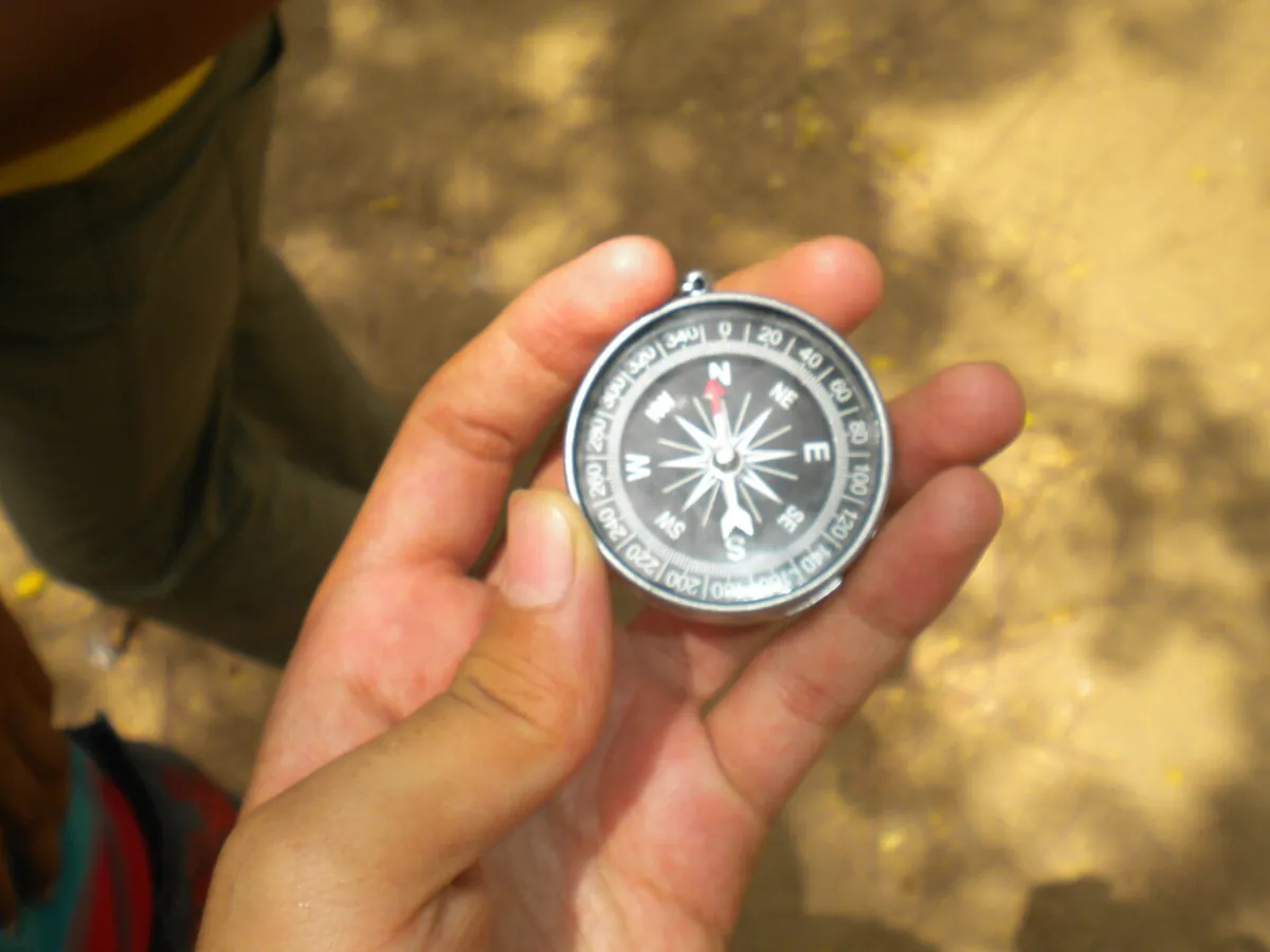
- Drones and phones: IMUs like the MPU-6050 measure tilt; a compass or other sensor is added to get heading (yaw).
Bench build
Bench build: measure orientation with an MPU-6050
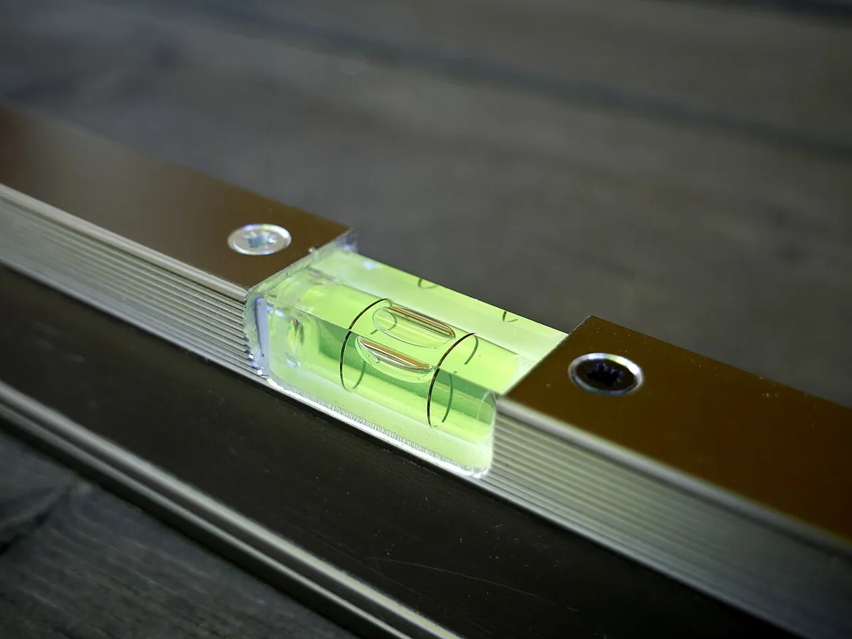
An MPU-6050 accelerometer feels gravity. When it is held still, the direction of gravity in the sensor’s own frame tells you its roll and pitch. tilt_orientation.ino reads the raw accelerometer over I²C and prints both angles. Tape the board flat to a ruler — the ruler is your ‘tool’ — and tilt it.
| MPU-6050 board | Arduino UNO | Note |
|---|---|---|
| VCC | 5 V or 3.3 V | 5 V only if your board has an on-board 3.3 V regulator; otherwise 3.3 V |
| GND | GND | — |
| SDA | A4 | I²C data |
| SCL | A5 | I²C clock |
Wire and upload
Open Serial Monitor at 115200. Lying flat, you should see az ≈ 1.00 g and roll ≈ 0°, pitch ≈ 0°.
Roll
Tilt the ruler sideways about its long axis. Roll changes; pitch stays near 0.
Pitch
Tilt the front end up. Pitch changes; roll stays near 0.
Try yaw
Keep it flat and turn it on the table like a compass. Roll and pitch don’t change — gravity cannot see yaw.
Check with a protractor
Hold the ruler at 30° pitch against a protractor. How close is the reading?
// tilt_orientation.ino - measure part of an ORIENTATION with an MPU-6050 (GY-521 board).
// When the board is still, the accelerometer feels only gravity. From that we get
// roll (tilt about x) and pitch (tilt about y). Yaw (turning about the vertical) cannot be
// seen from gravity - a compass or a camera is needed for that.
// Wiring: VCC -> 5 V ONLY if your board has an on-board 3.3 V regulator (check its listing);
//         a bare MPU-6050 board with no regulator must use 3.3 V. GND -> GND,
//         SDA -> A4, SCL -> A5. No motors in this build.
#include <Wire.h>
const int MPU = 0x68;

void setup() {
  Wire.begin();
  Wire.beginTransmission(MPU);
  Wire.write(0x6B);            // PWR_MGMT_1 register
  Wire.write(0);               // wake the sensor up
  Wire.endTransmission(true);
  Serial.begin(115200);
  Serial.println(F("ax_g, ay_g, az_g,  roll_deg, pitch_deg"));
}

int16_t read16() { int16_t hi = Wire.read(); return (hi << 8) | Wire.read(); }

void loop() {
  Wire.beginTransmission(MPU);
  Wire.write(0x3B);            // ACCEL_XOUT_H: first of six accelerometer bytes
  Wire.endTransmission(false);
  Wire.requestFrom(MPU, 6, true);
  float ax = read16() / 16384.0, ay = read16() / 16384.0, az = read16() / 16384.0;  // +-2 g range
  float roll = degrees(atan2(ay, az));
  float pitch = degrees(atan2(-ax, sqrt(ay * ay + az * az)));
  Serial.print(ax, 2); Serial.print(F(", ")); Serial.print(ay, 2); Serial.print(F(", "));
  Serial.print(az, 2); Serial.print(F(",  ")); Serial.print(roll, 1); Serial.print(F(", "));
  Serial.println(pitch, 1);
  delay(200);
}
Debugging
Debugging pose
| Symptom | Likely cause | Fix |
|---|---|---|
| Tool reaches the point but at a wrong angle | Only position was given | Give a full pose (x, y, φ) or (p, R) |
| det(R) = −1 | One axis flipped — a mirror, not a rotation | Check the frame with the right-hand rule |
| Columns not length 1 | Rounding or a wrongly typed matrix | Rebuild R from angles, or re-normalise |
| Roll/pitch swap or wrong sign | Board mounted turned | Check the x, y arrows printed on the board |
| Roll and pitch jump while moving | Accelerometer feels motion, not just gravity | Read only when still, or filter (Stage 7, Lesson 12) |
| Yaw never changes | Gravity can’t measure yaw | Use a compass, a gyro or a camera for yaw |
Think
Think about it
Think
Your 3-link planar arm must reach (14, 6). Imran says, “Why do we even need the third joint? The 2-link arm already reaches (14, 6).” What would you answer?
Experiment
Try it in the lab
About 30 minutes with the Python file, the frame explorer and (optionally) the MPU-6050 bench.
Experiment
Position vs orientation
You will need
- `pose.py` and Python 3
- Frame explorer (in your browser)
- A pen and a ruler
- Optional: Arduino UNO, MPU-6050 board, jumper wires, protractor
Steps
- Hold a pen above a dot on paper. Keep the tip on the dot and change only the direction. Write the pose in words.
- Run `pose.py`. Add φ = 135° to Part 1. Does it work? What happens with φ = 180°?
- Try a target near full reach, e.g. (20, 0). Which tool angles still work, and why do some return None?
- In Part 3, change the order to `matmul(ry(90), rz(30))`. Does R change? Do the three checks still pass?
- In the frame explorer, keep the origin fixed and turn only the yaw. Which numbers change?
- Optional: with the MPU-6050, measure roll and pitch at 0°, 30° and 60° against a protractor.
Interactive · Coordinate-frame explorer
The same position can have many orientations, and each needs different joint angles. Near the edge of the reach, fewer orientations are possible. Changing the order of rotations changes R — but every real R still passes the three checks.
Knowledge check
Check your understanding
Knowledge check
1. A pose combines…
2. How many numbers describe a planar (top-view) pose?
3. In a rotation matrix R, column 3 is…
4. A matrix has unit, perpendicular columns but det = −1. It is…
5. In pose.py, the tip reaches (14, 6) with φ = 0°, 45° and 90°. This shows that…
6. Why can’t an accelerometer lying flat measure yaw?
7. A general-purpose arm usually has six joints because…
Mini assignment
Hands-on assignment
Mini assignment
Pose cards
Describe three everyday tool tasks as poses and check one with code.
Deliverables
- Three task cards (e.g. pouring water, writing, turning a screw), each with a sketch of the tool frame and its position and orientation in words.
- For one card, a planar pose (x, y, φ) and the joint angles from `ik3()` with the FK check.
- A rotation matrix of your own from `rz()` and `ry()` with the three checks passing, and one sentence on what each column means.
- One sentence on why order matters for roll, pitch and yaw, with your Part 3 result as evidence.
- Optional: an MPU-6050 table of protractor angle vs measured roll and pitch.
Do this, step by step
- Run
python3 pose.py. For Part 1, choose one target (x, y, φ) and check thatfk3()of theik3()answer lands back on it. - Write three task cards (pouring, writing, turning a screw). On each, draw the tool frame and say in words where it is and which way its x axis points.
- For one card, put its planar pose into
ik3()withelbow=+1and thenelbow=-1. Record both sets of joint angles. - Build your own R with
matmul(rz(…), ry(…)), then check: columns of length 1, columns at right angles, det = +1. - Swap the order to
matmul(ry(…), rz(…))and write one sentence on why the result is different.
Stuck? Hints, one at a time
- φ is the direction the tool points, measured from the x axis, and in this planar arm it is θ₁ + θ₂ + θ₃.
- If
ik3()returns nothing, the wrist point is out of reach — try a different φ for the same (x, y). - Each column of R is one tool axis written in base coordinates.
Challenges (pick by level)
- 🟢 Easy: Write the pose of your pen in the frame of your notebook when it lies along the bottom edge.
- 🟢 Easy: Compute (cos φ, sin φ) for φ = 30° and 120° by hand.
- 🟡 Medium: Make
pose.pyprint, for (14, 6), every φ from 0° to 350° in 10° steps that has an IK answer. - 🟠 Hard-ish: Add an
rx()function and build R for roll 90°, then check the three conditions. - 🔴 Hard: Show with numbers that
rz(30)·ry(90)andry(90)·rz(30)are different matrices, and explain the difference in words. - ⚫ Research: Find out what a quaternion is and why many robot programs store orientation that way.
Next step
You now have position p and orientation R as separate pieces. In Lesson 4 — Homogeneous Transformation Matrices you will pack them into one 4 × 4 matrix T, so moving between frames becomes a single multiplication.
Look back: Lesson 2: Coordinate Frames & Reference Frames. Next: Lesson 4: Homogeneous Transformation Matrices. Related: Stage 1: Rotation and Stage 1: 3D Vectors.
Sources
- Wikipedia — Rotation matrix — a rotation matrix is orthogonal with determinant 1 (Rᵀ = R⁻¹, det R = 1); yaw, pitch and roll angles.
- Wikipedia — Pose (computer vision) — pose as the combination of position and orientation.
- Wikipedia — Aircraft principal axes — roll, pitch and yaw axes.
- Arduino Playground — MPU-6050 — I²C address 0x68, waking the sensor via PWR_MGMT_1 (0x6B), reading from ACCEL_XOUT_H (0x3B); some boards are 3.3 V only.
- Photos and diagram: Wikimedia Commons (credits under each image).
Self-attested for now — keep artifacts in your lab notebook.
Complete
Today's goal
0 of 1 done today
Mark this lesson complete when you have worked the experiment, knowledge check, and assignment (even roughly).